EP0655574A1 - Sicherheitsvorrichtung zur Öffnung oder Schliessung eines Schiebers - Google Patents
Sicherheitsvorrichtung zur Öffnung oder Schliessung eines Schiebers Download PDFInfo
- Publication number
- EP0655574A1 EP0655574A1 EP94402574A EP94402574A EP0655574A1 EP 0655574 A1 EP0655574 A1 EP 0655574A1 EP 94402574 A EP94402574 A EP 94402574A EP 94402574 A EP94402574 A EP 94402574A EP 0655574 A1 EP0655574 A1 EP 0655574A1
- Authority
- EP
- European Patent Office
- Prior art keywords
- ring
- control shaft
- shaft
- valve
- enclosure
- Prior art date
- Legal status (The legal status is an assumption and is not a legal conclusion. Google has not performed a legal analysis and makes no representation as to the accuracy of the status listed.)
- Granted
Links
- 239000012530 fluid Substances 0.000 claims abstract description 18
- 239000003999 initiator Substances 0.000 claims description 4
- 230000000149 penetrating effect Effects 0.000 abstract 1
- 239000007789 gas Substances 0.000 description 19
- 230000006835 compression Effects 0.000 description 3
- 238000007906 compression Methods 0.000 description 3
- 238000006073 displacement reaction Methods 0.000 description 2
- 239000002184 metal Substances 0.000 description 2
- 241001272720 Medialuna californiensis Species 0.000 description 1
- 239000000470 constituent Substances 0.000 description 1
- 238000009434 installation Methods 0.000 description 1
- 230000008018 melting Effects 0.000 description 1
- 238000002844 melting Methods 0.000 description 1
- 238000009527 percussion Methods 0.000 description 1
- 230000000284 resting effect Effects 0.000 description 1
- 238000007789 sealing Methods 0.000 description 1
- 238000010008 shearing Methods 0.000 description 1
Images




Classifications
-
- F—MECHANICAL ENGINEERING; LIGHTING; HEATING; WEAPONS; BLASTING
- F16—ENGINEERING ELEMENTS AND UNITS; GENERAL MEASURES FOR PRODUCING AND MAINTAINING EFFECTIVE FUNCTIONING OF MACHINES OR INSTALLATIONS; THERMAL INSULATION IN GENERAL
- F16K—VALVES; TAPS; COCKS; ACTUATING-FLOATS; DEVICES FOR VENTING OR AERATING
- F16K17/00—Safety valves; Equalising valves, e.g. pressure relief valves
- F16K17/36—Safety valves; Equalising valves, e.g. pressure relief valves actuated in consequence of extraneous circumstances, e.g. shock, change of position
- F16K17/38—Safety valves; Equalising valves, e.g. pressure relief valves actuated in consequence of extraneous circumstances, e.g. shock, change of position of excessive temperature
-
- A—HUMAN NECESSITIES
- A62—LIFE-SAVING; FIRE-FIGHTING
- A62C—FIRE-FIGHTING
- A62C2/00—Fire prevention or containment
- A62C2/04—Removing or cutting-off the supply of inflammable material
-
- F—MECHANICAL ENGINEERING; LIGHTING; HEATING; WEAPONS; BLASTING
- F16—ENGINEERING ELEMENTS AND UNITS; GENERAL MEASURES FOR PRODUCING AND MAINTAINING EFFECTIVE FUNCTIONING OF MACHINES OR INSTALLATIONS; THERMAL INSULATION IN GENERAL
- F16K—VALVES; TAPS; COCKS; ACTUATING-FLOATS; DEVICES FOR VENTING OR AERATING
- F16K31/00—Actuating devices; Operating means; Releasing devices
- F16K31/12—Actuating devices; Operating means; Releasing devices actuated by fluid
- F16K31/14—Actuating devices; Operating means; Releasing devices actuated by fluid for mounting on, or in combination with, hand-actuated valves
- F16K31/143—Actuating devices; Operating means; Releasing devices actuated by fluid for mounting on, or in combination with, hand-actuated valves the fluid acting on a piston
Definitions
- the present invention relates to the field of valve operating devices. More specifically, the invention relates to a device making it possible in the event of an accident to operate a valve which is normally controlled by a motor shaft actuated by a manual flywheel or by a motor.
- valves used on industrial sites are often valves with vertical displacement of the shutter of the "guillotine" valve type. These valves all have a control shaft coupled to a motor shaft actuated itself by a motor device which can be an electric, hydraulic, pneumatic motor or a manual flywheel.
- the object of the present invention is precisely to propose such a device.
- connection assembly is incorporated into the said ring.
- said source of fluid is a source of gas under pressure.
- said gas source is a pressurized gas tank provided with a tap.
- said tap will be a pyrotechnic tap with electric control or actuated by a striker.
- said gas source is a pyrotechnic gas generator provided with an initiator with electrical triggering or with percussion triggering.
- the end of the drive shaft enters the end of the control shaft which is hollow.
- said contact part is advantageously a shearing part such as a shearable pin which secures both the ring, the control shaft as well as the motor shaft and the end of the control shaft comprises at least a transverse conduit in which are arranged, on either side of the drive shaft, at least two balls which are radially wedged by the ring and which bear against the bottom of a circular groove carried by the end of the 'engine shaft.
- the end of the control shaft as well as the end of the motor shaft are widened and rest one on the other, enclosed in at least two U-shaped holding tabs which are themselves -same arranged in a cylindrical upper recess presented by the ring.
- the contact piece is advantageously a thrust spring bearing, on the one hand, on the stopper and, on the other hand, on the ring.
- the first two variants allow a particularly advantageous embodiment of the invention when the sealed ring does not directly enclose the ends of the two shafts but supports a connection assembly which, in turn, encloses the ends of the two shafts.
- the said enclosure has a lower orifice which is located so as to be below the said ring when the valve is closed and which is also connected to a source of fluid; also said control shaft has a second stop arranged so as to be above said ring and inside said enclosure regardless of the position of the shutter.
- the valve maneuver in opening or closing, is obtained by the action of the driving shaft driven by an engine block or by a manual flywheel.
- the valve is closed using the safety device according to the invention. To do this the fluid is brought into the hollow enclosure through the orifice located above the sealed ring.
- the motor shaft is no longer integral with the valve control shaft and the sealed ring bearing on the stopper carried by the control shaft plays the role of piston which, under the fluid pressure action, causes the valve to close by lowering the shutter.
- the operation of the valve in normal operation, is obtained by the action of the motor shaft driven by an engine block or by a manual flywheel.
- the fluid arrives in the hollow enclosure either through the upper orifice if one wants to close the valve, or through the lower orifice if one wants to open the valve.
- the arrival of the fluid causes the contact part to retract and the sealing ring to move up to the stopper disposed under the ring if the fluid arrives through the upper orifice or to the stopper disposed above the ring if the fluid arrives through the lower orifice.
- the motor shaft is no longer integral with the valve control shaft and the sealed ring bearing on one of the stop stops acts as a piston which, under the action of pressure of fluid, causes either the closing of the valve by lowering the shutter, or the opening of the valve by raising the shutter, with sliding in the hollow end presented by one of the two shafts of the end from the other tree.
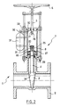
- Figure 1 is a sectional view of a valve, in the open position, and provided with a safety closure device according to the first preferred embodiment.
- Figure 2 is a sectional view of the valve shown in Figure 1 after operation of the safety device.
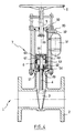
- Figure 3 is a sectional view of a valve, in the open position, and provided with a safety closure device according to the third preferred embodiment.
- Figure 4 is a sectional view of the valve shown in Figure 3 after operation of the safety device.
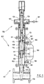
- FIG. 5 shows, in cross-section, a valve in the "open” position for which the control shaft enters the motor shaft and which has a device opening and closing safety according to the particular embodiment of the invention.
- FIG. 6 represents, in section view, the same valve after operating in "closing" of the safety device.
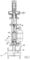
- Figure 7 shows, in sectional view, the same valve in the "closed” position.
- FIG. 8 represents, in section view, the same valve after operating in "opening" of the safety device.
- FIGS. 1 and 2 show a valve 1 provided with a safety closing device according to the invention.
- the valve 1 comprises a hollow body 2 interposed between two pipes not shown in the figures.
- This frame 2 can be closed by a shutter 3 which moves in translation and which is controlled by a control shaft 4.
- a control shaft 4 Such a valve is also known by the names. "gate valve” or "knife gate valve”.
- the control shaft 4 is itself actuated by a rotary motor shaft 5 disposed in the extension of the control shaft 4.
- the motor shaft 5 is driven by an engine block or by a manual flywheel 6 as shown in the figures.
- the shutter 3 is a flat shutter with a dihedral-shaped section into which the lower end 34 of the control shaft 4 penetrates. This end 34 is enlarged and contained in an appropriate recess presented by the shutter 3.
- the shutter 3 and the control shaft 4 is integral in translation but the control shaft 4 is free to rotate relative to the shutter 3.
- the motor shaft 5 is secured to the control shaft 4 by a connection system 7 which is now described in detail.
- the connection system 7 comprises a hollow cylindrical enclosure 8 fixed to the body 2 of the valve 1 as shown in the figures and into which each of the said shafts 4 and 5 penetrate.
- the body 2 comprises an upper neck 9 in which the shutter 3 when valve 1 is open. It is on this neck 9 that the cylindrical enclosure 8 fixed by means of threaded fixing bars 10 rests.
- the enclosure 8 is closed by a cover 11 having a central orifice and crossed by the fixing bars 10.
- the enclosure 8 is fixed by bolts 12 to the upper part of the neck 9 and the cover 11 is fixed by bolts 13 to the enclosure 8.
- Seals 14, 15, 16 and 36 make the assembly constituted by the neck 9, the enclosure 8 and the waterproof cover 11.
- the fixing bars 10 also carry in their upper part a nut 17 having a threaded central orifice in which meshes a thread 18 carried by the motor shaft 5.
- Said hollow enclosure 8 contains a gas-tight cylindrical ring 19 which simultaneously encloses the end 20 of the control shaft 4 and the end 21 of the motor shaft 5 which are located inside said enclosure. This ring 19 itself secured to one of the two shafts 4 and 5 by means of a retractable contact piece under the action of a pressure of predetermined value exerted on said ring.
- said contact part is a shear pin 22 which passes through both the ring 19, the control shaft 4 and the motor shaft 5.
- the ring 19 includes a central hole whose diameter is equal to the diameter of the control shaft 4 and it is placed around the end 20 of this shaft.
- the ring 19 has a lower part whose diameter is equal to the inside diameter of the enclosure 8 and which contains seals 23 and 24 ensuring gas tightness.
- the ring 19 has an upper part of narrower diameter through which the pin 22 passes.
- the end 21 of the motor shaft 5 penetrates into the end 20 of the control shaft which is hollow so that the pin 22 crosses both the ring 19, the control shaft 4 and the motor shaft 5.
- a hollow cylindrical conduit 25 is formed through the upper part 20 of the control shaft 4 into which the end 21 of the motor shaft 5.
- a circular groove 26 is formed on said end 21 so as to be opposite the conduit 25 when the motor shaft 5 is introduced into the control shaft 4.
- Two metal balls 27 and 28 are introduced into said conduit 25 on either side of the shaft motor 5 and are locked by the ring 19 so as to bear on the bottom of the groove 26.
- a second conduit 35 will be provided, perpendicular to the conduit 25 which has just been described, and which also contains two balls not shown in the figures.
- said contact part is a spring 51 bearing, on the one hand, on a stopper 29 carried by the control shaft 4 and which will be detailed a little later in the description and, on the other hand, on a ring 52 similar in principle to the ring 19 previously described.
- the ring 52 is a hollow cylindrical ring comprising an upper part whose external diameter corresponds to the internal diameter of the enclosure 8 and a lower part of smaller external diameter.
- the ring 52 has in its upper part a cylindrical upper recess 53 whose diameter is greater than that of the control shaft 4.
- This recess 53 is extended by an orifice whose diameter is equal to that of the control shaft 4 and ends with a lower recess 54 whose diameter is greater than that of the control shaft 4.
- Seals 55, 56 and 57 ensure the seal of the ring 52 to gases.
- the end 59 of the motor shaft 5 rests on the end 58 of the control shaft 4. As shown in the figures, these ends are enlarged relative to their bearing shafts. They are advantageously constituted by rollers screwed onto threaded spikes carried by said trees.
- Said enclosure 8 typically comprises an orifice 30 situated so as to be located above said ring 19 or 52 when the valve 1 is open and the shutter 3 is located in the neck 9 of the frame 2.
- This orifice 30 is also designated in the present description as "upper orifice”.
- control shaft 4 carries a stopper 29.
- This stopper 29 is arranged so as to be, as shown in the FIGS. 1 to 4, under said ring 19 or 52 and inside the enclosure 8 whatever the position of the shutter 3.
- a source 31 of pressurized gas is connected to said orifice 30.
- said source 31 can be a pressurized gas tank provided with a tap 32 connected to the orifice 30 by a pipe 33.
- Said tap 32 will advantageously be a pyrotechnic tap with electrical control or well actuated by a striker.
- Said gas source can also be a pyrotechnic gas generator provided with an electrically controlled initiator or else actuated by a striker.
- the pressurized gas enters the enclosure 8 through the orifice 30 and exerts pressure on the ring 19.
- the force exerted on the ring is greater than the breaking limit of the pin 22, the latter breaks and the ring 19 is pushed until it comes into contact with the stop 29.
- the ring 19 bearing on the stop 27 plays the role of a piston which, under the pressure of the gas, drives the control shaft 4 which is no longer integral with the motor shaft 5.
- the shaft 4 can therefore descend without having to force the gear 18. With a relatively small amount of energy, it is therefore possible to lower the shutter 3 and close the valve 1.
- the safety device shown in Figures 3 and 4 has a completely similar operation. Normally it is the motor shaft 5 which drives the control shaft 4 up or down. In the event of an accident occurring when the valve 1 is open, the arrival of pressurized gas through the orifice 30 develops pressure on the ring 52. When the force exerted on this ring is greater than the resistance of the spring 51, the latter compresses and the ring 52 descends along the control shaft 4 until the spring 51 is fully compressed against the stop 29. The retaining tabs 60, 61 and 62 no longer being maintained they separate and fall on the ring 52 and the two shafts are no longer integral. The ring 52 bearing on the stop 29 via the spring 51 then plays the role of a piston which drives the control shaft 4 without having to force the gear 18. The descent of the control shaft 4 causes the shutter 3 to descend, which closes the valve 1.
- valve 101 equipped with a safety device operating in opening and closing according to the particular embodiment of the invention.
- the valve 101 consists of a body 102 interposed between two pipes not shown in the figures.
- This body 102 is surmounted by a neck 109 on which is fixed a sealed enclosure 108 closed in its upper part by a cover 111 having a central orifice.
- a shutter 103 is housed in the neck 109 when the valve 101 is open.
- the shutter 103 is a flat shutter with a dihedral shape.
- This shutter 103 is extended by a control shaft 104 which penetrates into the enclosure 108.
- the control shaft 104 is integral in translation with the shutter 103 but is fixed in rotation relative to the latter.
- a drive shaft 105 enters the enclosure 108 and is secured in translation with the control shaft 104 by a connection system 107 which will be described in detail a little later.
- the part of the motor shaft 105 situated outside the sealed enclosure 108 is contained in a frame 178.
- the upper part of the motor shaft 105 has an external thread 179 which meshes in a rotating nut 180 actuated in rotation by a drive shaft 181 controlled by a motor or by a manual flywheel. It should be observed that in this embodiment the motor shaft 105 is fixed in rotation because it is secured to the control shaft 104 which is fixed relative to the shutter 103 which only moves in translation. The rotation of the nut 180 therefore only causes the motor shaft 105 to rise or fall, which drives the control shaft 104 and the shutter 103.
- the lower part 121 of the motor shaft 105 is hollow. This hollow part may constitute only one piece with the rest of the shaft 105 or be constituted by a hollow tube screwed onto the shaft 105 proper as shown in the figures. It is this hollow lower part which enters the enclosure 108. The upper end 120 of the shaft control 104 enters this hollow lower part 121 of the motor shaft 105.
- connection system of the two shafts comprises a ring 119 carried by the motor shaft 104. Seals 182 and 183 disposed on the one hand between the ring 119 and the shaft 104 and on the other hand between the ring 119 and the enclosure 108 make this ring gas tight.
- the ring 119 supports a connection assembly which is constituted by rigid keys 160 and 161 arranged in two cells 173 and 174 carried by the hollow end 121 of the motor shaft 105 and held in abutment against a groove 172 carried by the end 120 of the control shaft 104 by means of a circular crown 175 connected in a non-deformable manner to said ring 119 by rigid rods 176.
- the constituent elements of said connection assembly are in particular visible in FIG. 6.
- the keys 160 and 161 must be non-deformable. In order to be easily ejected from the cells 173 and 174 they will advantageously be in the form of a prism or half-moon. We can, for the same purpose, also provide an ejection spring disposed between the keys in an orifice passing through the groove 172.
- the circular crown 175 does not have to be gas-tight, it can advantageously be in the shape of a star.
- control shaft 104 comprises a first stopper 129 arranged so as to be located under the ring 119 and inside the enclosure 108 whatever the position of the shutter 103 and a second stop stop 171 arranged so as to be above of the ring 119 and inside the enclosure 108 whatever the position of the shutter 103.
- the contact piece is constituted by a first thrust spring 151 bearing on the one hand on the ring 119 and on the other hand on the stop 129 located under said ring and by a second thrust spring 177 bearing on the one hand on the ring 119 and on the other hand on the stop 171 located above said ring.
- the springs 151 and 177 are pre-stressed springs whose compression tension must be greater than the friction stresses of the ring 119 against the interior surface of the enclosure 108. In practice, the choice of such springs will be easy because the frictional stresses of the ring 119 against the interior surface of the enclosure 108 are a few kg while the forces exerted on the ring in the event of the use of the safety device. will be several tonnes.
- the sealed enclosure 108 comprises, in addition to an upper orifice 130 situated so as to be located above the ring 119 when the valve is normally open, a lower orifice 170 situated so to be below the ring 119 when the valve is normally closed.
- normally open or “normally closed” is meant that the valve is opened or closed by actuation of the rotary drive shaft 181.
- Said orifices are connected to a source of fluid. They may be separate sources or, as shown in FIGS. 5 to 8, a single source 184.
- the upper orifice 130 is connected by a pipe 187 and by a tap 185 to this source while the orifice lower 170 is connected to this source by a separate pipe 188 and by a separate tap 186.
- the fluid source 184 will be a source of pressurized gas and the taps 185 and 186 will be electrically controlled pyrotechnic taps operating on a secondary network separate from the main circuit of the site or will be operated by a striker.
- the opening of the valve 185 allows the pressurized gas to enter the enclosure 108 through the orifice 130.
- the force exerted on the ring 119 is greater than the resistance of the spring 151, the latter compresses and the ring 119 descends along the control shaft 104 until total compression of the spring 151 against the stop 129 by driving through the rods 176 the crown 175.
- the keys 160 and 161 are no longer maintained, they are ejected from the cells 173 and 174 and fall on the crown 175.
- the two shafts 104 and 105 are no longer integral.
- the ring 119 bearing on the stop 129 via the compressed spring 151 then plays the role of a piston to drive the control shaft 104 without having to force the gear of the shaft 105 in the nut 180.
- the descent of the control shaft 104 brings about the descent of the shutter 103 which closes the valve 101 as shown in FIG. 6.
- the opening of the valve 186 allows the pressurized gas to enter the enclosure 108 through the orifice 170.
- the force exerted on the ring 119 is greater than the resistance of the spring 177 the latter compresses and the ring 119 rises along the control shaft 104 until total compression of the spring 177 against the stop 171 by driving through the rods 176 the crown 175.
- the keys 160 and 161 no longer maintained, they are ejected from the cells 173 and 174 and fall on the stop 171.
- the two shafts 104 and 105 are no longer integral.
- the ring 119 resting on the stop 171 via the compressed spring 177 then plays the role of a piston to push the end 120 of the control shaft 104 into the hollow part 121 of the motor shaft 105 without having to force the gear of the shaft 105 into the nut 180.
- the rise of the control shaft 104 causes the shutter 103 to rise, which opens the valve 101 as shown in FIG. 8.
Landscapes
- Engineering & Computer Science (AREA)
- General Engineering & Computer Science (AREA)
- Mechanical Engineering (AREA)
- Health & Medical Sciences (AREA)
- Public Health (AREA)
- Business, Economics & Management (AREA)
- Emergency Management (AREA)
- Safety Valves (AREA)
- Electrically Driven Valve-Operating Means (AREA)
- Control Of Throttle Valves Provided In The Intake System Or In The Exhaust System (AREA)
- Fluid-Driven Valves (AREA)
- Mechanically-Actuated Valves (AREA)
Applications Claiming Priority (5)
| Application Number | Priority Date | Filing Date | Title |
|---|---|---|---|
| FR9314084 | 1993-11-25 | ||
| FR9314084A FR2712955B1 (fr) | 1993-11-25 | 1993-11-25 | Dispositif de manÓoeuvre d'une vanne à obturateur se déplaçant par translation. |
| FR9402158 | 1994-02-25 | ||
| FR9402158A FR2712954B1 (fr) | 1993-11-25 | 1994-02-25 | Dispositif d'ouverture et de fermeture de sécurité d'une vanne à obturateur se déplaçant par translation. |
| JP7076330A JPH08277950A (ja) | 1993-11-25 | 1995-03-31 | バルブを安全に作動する装置及びその使用方法 |
Publications (2)
| Publication Number | Publication Date |
|---|---|
| EP0655574A1 true EP0655574A1 (de) | 1995-05-31 |
| EP0655574B1 EP0655574B1 (de) | 1998-04-08 |
Family
ID=27252827
Family Applications (1)
| Application Number | Title | Priority Date | Filing Date |
|---|---|---|---|
| EP94402574A Expired - Lifetime EP0655574B1 (de) | 1993-11-25 | 1994-11-15 | Sicherheitsvorrichtung zur Öffnung oder Schliessung eines Schiebers |
Country Status (5)
| Country | Link |
|---|---|
| EP (1) | EP0655574B1 (de) |
| JP (1) | JPH08277950A (de) |
| DE (1) | DE69409470T2 (de) |
| ES (1) | ES2114670T3 (de) |
| FR (2) | FR2712955B1 (de) |
Cited By (8)
| Publication number | Priority date | Publication date | Assignee | Title |
|---|---|---|---|---|
| FR2736703A1 (fr) * | 1995-07-13 | 1997-01-17 | Pyromeca Sa | Dispositif de fermeture de securite pour vanne, comportant un verin exterieur |
| FR2795480A1 (fr) * | 1999-06-28 | 2000-12-29 | Pyroalliance | Actionneur de secours pour robinets et vannes de grand diametre comportant un obturateur a translation |
| WO2009039042A1 (en) * | 2007-09-21 | 2009-03-26 | Fisher Controls International Llc | Apparatus and methods for manual override operation of a linear actuator |
| WO2010090816A1 (en) * | 2009-02-04 | 2010-08-12 | Fisher Controls International Llc | Manual override apparatus for linear actuators |
| CN104145147A (zh) * | 2012-02-29 | 2014-11-12 | 法克有限公司 | 具有集成加压气体储藏器的气动闸门阀 |
| CN105952950A (zh) * | 2016-06-30 | 2016-09-21 | 天津市津达执行器有限公司 | 一种双手轮电动执行器 |
| CN108980382A (zh) * | 2018-08-02 | 2018-12-11 | 繁昌县长城铸造厂(普通合伙) | 一种新型闸阀装置 |
| CN114183552A (zh) * | 2021-12-17 | 2022-03-15 | 江苏柏斯克石油机械有限公司 | 一种便于使用的石油钻采用平板阀及其使用方法 |
Families Citing this family (1)
| Publication number | Priority date | Publication date | Assignee | Title |
|---|---|---|---|---|
| DE29512700U1 (de) * | 1995-08-07 | 1996-12-05 | Max Widenmann Armaturenfabrik, 89537 Giengen | Druckventil |
Citations (8)
| Publication number | Priority date | Publication date | Assignee | Title |
|---|---|---|---|---|
| US2890014A (en) * | 1955-12-19 | 1959-06-09 | Worthington Corp | Pressure responsive valve |
| DE1113344B (de) * | 1957-12-18 | 1961-08-31 | Acf Ind Inc | Kombinierter Druckmittel- und Handantrieb fuer Ventile u. dgl. taetige Verschluesse |
| FR1300618A (fr) * | 1961-09-18 | 1962-08-03 | Jansen Gmbh Th | Vanne d'arrêt à surfaces de joint obliques |
| FR1429396A (fr) * | 1965-01-13 | 1966-02-18 | Rateau Soc | Perfectionnement aux vérins |
| FR2241737A1 (de) * | 1973-08-24 | 1975-03-21 | Philadelphia Gear Corp | |
| FR2450398A1 (fr) * | 1979-03-01 | 1980-09-26 | Borg Warner | Servomoteur d'actionnement de vanne |
| FR2520473A1 (fr) * | 1982-01-25 | 1983-07-29 | Ava Int Corp | Robinet-vanne de securite et son dispositif de commande |
| EP0145828A2 (de) * | 1983-12-10 | 1985-06-26 | Streif, Hans | Absperrarmatur für Gasleitungen |
-
1993
- 1993-11-25 FR FR9314084A patent/FR2712955B1/fr not_active Expired - Lifetime
-
1994
- 1994-02-25 FR FR9402158A patent/FR2712954B1/fr not_active Expired - Fee Related
- 1994-11-15 ES ES94402574T patent/ES2114670T3/es not_active Expired - Lifetime
- 1994-11-15 EP EP94402574A patent/EP0655574B1/de not_active Expired - Lifetime
- 1994-11-15 DE DE69409470T patent/DE69409470T2/de not_active Expired - Fee Related
-
1995
- 1995-03-31 JP JP7076330A patent/JPH08277950A/ja active Pending
Patent Citations (8)
| Publication number | Priority date | Publication date | Assignee | Title |
|---|---|---|---|---|
| US2890014A (en) * | 1955-12-19 | 1959-06-09 | Worthington Corp | Pressure responsive valve |
| DE1113344B (de) * | 1957-12-18 | 1961-08-31 | Acf Ind Inc | Kombinierter Druckmittel- und Handantrieb fuer Ventile u. dgl. taetige Verschluesse |
| FR1300618A (fr) * | 1961-09-18 | 1962-08-03 | Jansen Gmbh Th | Vanne d'arrêt à surfaces de joint obliques |
| FR1429396A (fr) * | 1965-01-13 | 1966-02-18 | Rateau Soc | Perfectionnement aux vérins |
| FR2241737A1 (de) * | 1973-08-24 | 1975-03-21 | Philadelphia Gear Corp | |
| FR2450398A1 (fr) * | 1979-03-01 | 1980-09-26 | Borg Warner | Servomoteur d'actionnement de vanne |
| FR2520473A1 (fr) * | 1982-01-25 | 1983-07-29 | Ava Int Corp | Robinet-vanne de securite et son dispositif de commande |
| EP0145828A2 (de) * | 1983-12-10 | 1985-06-26 | Streif, Hans | Absperrarmatur für Gasleitungen |
Cited By (18)
| Publication number | Priority date | Publication date | Assignee | Title |
|---|---|---|---|---|
| FR2736703A1 (fr) * | 1995-07-13 | 1997-01-17 | Pyromeca Sa | Dispositif de fermeture de securite pour vanne, comportant un verin exterieur |
| FR2795480A1 (fr) * | 1999-06-28 | 2000-12-29 | Pyroalliance | Actionneur de secours pour robinets et vannes de grand diametre comportant un obturateur a translation |
| US8282070B2 (en) | 2007-09-21 | 2012-10-09 | Fisher Controls International Llc | Apparatus and methods for manual override operation of a linear actuator |
| WO2009039042A1 (en) * | 2007-09-21 | 2009-03-26 | Fisher Controls International Llc | Apparatus and methods for manual override operation of a linear actuator |
| CN101828060B (zh) * | 2007-09-21 | 2015-02-25 | 费希尔控制产品国际有限公司 | 用于线性致动器的手动超控操作的装置和方法 |
| RU2523458C2 (ru) * | 2009-02-04 | 2014-07-20 | Фишер Контролз Интернешнел Ллс | Устройство перевода на ручное управление для линейных приводов |
| CN102308134A (zh) * | 2009-02-04 | 2012-01-04 | 费希尔控制国际公司 | 用于线性致动器的手动超控设备 |
| CN102308134B (zh) * | 2009-02-04 | 2013-09-04 | 费希尔控制国际公司 | 用于线性致动器的手动超控设备 |
| US8070127B2 (en) | 2009-02-04 | 2011-12-06 | Fisher Controls International, Llc | Manual override apparatus for linear actuators |
| WO2010090816A1 (en) * | 2009-02-04 | 2010-08-12 | Fisher Controls International Llc | Manual override apparatus for linear actuators |
| AU2010210944B2 (en) * | 2009-02-04 | 2016-02-25 | Fisher Controls International Llc | Manual override apparatus for linear actuators |
| CN104145147A (zh) * | 2012-02-29 | 2014-11-12 | 法克有限公司 | 具有集成加压气体储藏器的气动闸门阀 |
| JP2015512016A (ja) * | 2012-02-29 | 2015-04-23 | ファイク・コーポレーションFike Corporation | 一体型加圧ガス貯留室を備えた空気式ゲートバルブ |
| CN104145147B (zh) * | 2012-02-29 | 2016-08-24 | 法克有限公司 | 具有集成加压气体储藏器的气动闸门阀 |
| CN105952950A (zh) * | 2016-06-30 | 2016-09-21 | 天津市津达执行器有限公司 | 一种双手轮电动执行器 |
| CN108980382A (zh) * | 2018-08-02 | 2018-12-11 | 繁昌县长城铸造厂(普通合伙) | 一种新型闸阀装置 |
| CN114183552A (zh) * | 2021-12-17 | 2022-03-15 | 江苏柏斯克石油机械有限公司 | 一种便于使用的石油钻采用平板阀及其使用方法 |
| CN114183552B (zh) * | 2021-12-17 | 2024-06-04 | 江苏苏博石化机械有限公司 | 一种便于使用的石油钻采用平板阀及其使用方法 |
Also Published As
| Publication number | Publication date |
|---|---|
| FR2712954B1 (fr) | 1995-12-22 |
| DE69409470T2 (de) | 1998-09-03 |
| ES2114670T3 (es) | 1998-06-01 |
| EP0655574B1 (de) | 1998-04-08 |
| FR2712955B1 (fr) | 1995-12-22 |
| DE69409470D1 (de) | 1998-05-14 |
| FR2712955A1 (fr) | 1995-06-02 |
| JPH08277950A (ja) | 1996-10-22 |
| FR2712954A1 (fr) | 1995-06-02 |
Similar Documents
| Publication | Publication Date | Title |
|---|---|---|
| FR2482556A1 (fr) | Dispositif pour vider sans danger des bombes de projection d'aerosols | |
| EP0655574B1 (de) | Sicherheitsvorrichtung zur Öffnung oder Schliessung eines Schiebers | |
| EP0296936B1 (de) | Antriebsvorrichtung zum schnellen und geregelten Trennen von zwei miteinander verbundenen Teilen | |
| CA2270579A1 (fr) | Dispositif de maintien en position de la tige d'un verin hydraulique | |
| FR2461087A1 (fr) | Carottier pour la remontee de carottes sous pression | |
| FR2468800A1 (fr) | Ensemble d'une trappe a ouverture rapide pour trou d'homme dans un recipient sous pression | |
| FR2563272A1 (fr) | Appareillage de sectionnement de ligne de service dans un puits de petrole ou de gaz | |
| FR2549275A1 (fr) | Coffre a ouverture assistee pour la protection d'un appareillage se presentant sous la forme d'un poteau | |
| EP0692260B1 (de) | Vorrichtung für Hochdruckbehandlung von Produkten in biegsamen Verpackungen | |
| EP0208570A1 (de) | Verfahren und Vorrichtung zum Öffnen eines Behälters für aufblasbare Gegenstände, zum Beispiel Rettungsrutsche | |
| FR2477217A1 (fr) | Systeme de rincage pour outil carottier pour la remontee de carottes sous pression | |
| EP1069355B1 (de) | Sicherheitsventil für Druckbehälter | |
| FR2658896A1 (fr) | Dispositif destine a differer l'ouverture d'une soupape. | |
| EP0061964A1 (de) | Zu oder geöffnetes sprengladungbetätigtes Ventil | |
| EP0656497B1 (de) | Sicherheitseinrichtung für ein Drehventil | |
| CA1291026C (fr) | Vanne de securite pour puits petrolier et outil de montage de ladite vanne | |
| FR2576966A1 (fr) | Ensemble de securite annulaire pour puits petrolier, en particulier a double zone de production | |
| FR2736703A1 (fr) | Dispositif de fermeture de securite pour vanne, comportant un verin exterieur | |
| FR2860915A1 (fr) | Dispositif d'actionnement de disjoncteur hybride a haute tension et disjoncteur ainsi equipe | |
| EP0274452A2 (de) | Vorrichtung zum Aufstechen von Druckgasflaschen | |
| FR2596140A1 (fr) | Dispositif pour le remplissage de recipients sous pression particulierement de bouteilles avec robinet a volant | |
| CA1117864A (fr) | Dispositif de colmatage rapide des fuites de petrole des puits sous pression | |
| FR2512098A1 (fr) | Verrou de securite a ouverture pyrotechnique | |
| EP0260166B1 (de) | Als Gasdruck-Behälter ausgeführtes flaschenförmiges Gerät | |
| EP0367655A1 (de) | Betätigungsvorrichtung für den Abfluss eines unter Druck stehenden Mediums aus einem Behälter |
Legal Events
| Date | Code | Title | Description |
|---|---|---|---|
| PUAI | Public reference made under article 153(3) epc to a published international application that has entered the european phase |
Free format text: ORIGINAL CODE: 0009012 |
|
| AK | Designated contracting states |
Kind code of ref document: A1 Designated state(s): DE ES GB IT NL |
|
| 17P | Request for examination filed |
Effective date: 19951113 |
|
| GRAG | Despatch of communication of intention to grant |
Free format text: ORIGINAL CODE: EPIDOS AGRA |
|
| 17Q | First examination report despatched |
Effective date: 19970618 |
|
| GRAG | Despatch of communication of intention to grant |
Free format text: ORIGINAL CODE: EPIDOS AGRA |
|
| GRAH | Despatch of communication of intention to grant a patent |
Free format text: ORIGINAL CODE: EPIDOS IGRA |
|
| RAP1 | Party data changed (applicant data changed or rights of an application transferred) |
Owner name: PYROMECA S.A. |
|
| GRAH | Despatch of communication of intention to grant a patent |
Free format text: ORIGINAL CODE: EPIDOS IGRA |
|
| RAP1 | Party data changed (applicant data changed or rights of an application transferred) |
Owner name: PYROALLIANCE |
|
| GRAA | (expected) grant |
Free format text: ORIGINAL CODE: 0009210 |
|
| AK | Designated contracting states |
Kind code of ref document: B1 Designated state(s): DE ES GB IT NL |
|
| ITF | It: translation for a ep patent filed | ||
| GBT | Gb: translation of ep patent filed (gb section 77(6)(a)/1977) |
Effective date: 19980409 |
|
| REF | Corresponds to: |
Ref document number: 69409470 Country of ref document: DE Date of ref document: 19980514 |
|
| REG | Reference to a national code |
Ref country code: ES Ref legal event code: FG2A Ref document number: 2114670 Country of ref document: ES Kind code of ref document: T3 |
|
| PLBE | No opposition filed within time limit |
Free format text: ORIGINAL CODE: 0009261 |
|
| STAA | Information on the status of an ep patent application or granted ep patent |
Free format text: STATUS: NO OPPOSITION FILED WITHIN TIME LIMIT |
|
| 26N | No opposition filed | ||
| PGFP | Annual fee paid to national office [announced via postgrant information from national office to epo] |
Ref country code: GB Payment date: 20001115 Year of fee payment: 7 |
|
| PGFP | Annual fee paid to national office [announced via postgrant information from national office to epo] |
Ref country code: ES Payment date: 20001116 Year of fee payment: 7 |
|
| PGFP | Annual fee paid to national office [announced via postgrant information from national office to epo] |
Ref country code: NL Payment date: 20001130 Year of fee payment: 7 |
|
| PGFP | Annual fee paid to national office [announced via postgrant information from national office to epo] |
Ref country code: DE Payment date: 20010130 Year of fee payment: 7 |
|
| PG25 | Lapsed in a contracting state [announced via postgrant information from national office to epo] |
Ref country code: GB Free format text: LAPSE BECAUSE OF NON-PAYMENT OF DUE FEES Effective date: 20011115 |
|
| PG25 | Lapsed in a contracting state [announced via postgrant information from national office to epo] |
Ref country code: ES Free format text: LAPSE BECAUSE OF NON-PAYMENT OF DUE FEES Effective date: 20011116 |
|
| REG | Reference to a national code |
Ref country code: GB Ref legal event code: IF02 |
|
| PG25 | Lapsed in a contracting state [announced via postgrant information from national office to epo] |
Ref country code: NL Free format text: LAPSE BECAUSE OF NON-PAYMENT OF DUE FEES Effective date: 20020601 |
|
| PG25 | Lapsed in a contracting state [announced via postgrant information from national office to epo] |
Ref country code: DE Free format text: LAPSE BECAUSE OF NON-PAYMENT OF DUE FEES Effective date: 20020702 |
|
| NLV4 | Nl: lapsed or anulled due to non-payment of the annual fee |
Effective date: 20020601 |
|
| REG | Reference to a national code |
Ref country code: ES Ref legal event code: FD2A Effective date: 20021213 |
|
| PG25 | Lapsed in a contracting state [announced via postgrant information from national office to epo] |
Ref country code: IT Free format text: LAPSE BECAUSE OF NON-PAYMENT OF DUE FEES;WARNING: LAPSES OF ITALIAN PATENTS WITH EFFECTIVE DATE BEFORE 2007 MAY HAVE OCCURRED AT ANY TIME BEFORE 2007. THE CORRECT EFFECTIVE DATE MAY BE DIFFERENT FROM THE ONE RECORDED. Effective date: 20051115 |