EP0655765A1 - Canon à électrons pour tube image couleur - Google Patents
Canon à électrons pour tube image couleur Download PDFInfo
- Publication number
- EP0655765A1 EP0655765A1 EP94118718A EP94118718A EP0655765A1 EP 0655765 A1 EP0655765 A1 EP 0655765A1 EP 94118718 A EP94118718 A EP 94118718A EP 94118718 A EP94118718 A EP 94118718A EP 0655765 A1 EP0655765 A1 EP 0655765A1
- Authority
- EP
- European Patent Office
- Prior art keywords
- focusing
- electrodes
- voltages
- lens
- electron gun
- Prior art date
- Legal status (The legal status is an assumption and is not a legal conclusion. Google has not performed a legal analysis and makes no representation as to the accuracy of the status listed.)
- Withdrawn
Links
Images


Classifications
-
- H—ELECTRICITY
- H01—ELECTRIC ELEMENTS
- H01J—ELECTRIC DISCHARGE TUBES OR DISCHARGE LAMPS
- H01J29/00—Details of cathode-ray tubes or of electron-beam tubes of the types covered by group H01J31/00
- H01J29/46—Arrangements of electrodes and associated parts for generating or controlling the ray or beam, e.g. electron-optical arrangement
- H01J29/56—Arrangements for controlling cross-section of ray or beam; Arrangements for correcting aberration of beam, e.g. due to lenses
-
- H—ELECTRICITY
- H01—ELECTRIC ELEMENTS
- H01J—ELECTRIC DISCHARGE TUBES OR DISCHARGE LAMPS
- H01J29/00—Details of cathode-ray tubes or of electron-beam tubes of the types covered by group H01J31/00
- H01J29/46—Arrangements of electrodes and associated parts for generating or controlling the ray or beam, e.g. electron-optical arrangement
- H01J29/48—Electron guns
- H01J29/50—Electron guns two or more guns in a single vacuum space, e.g. for plural-ray tube
- H01J29/503—Three or more guns, the axes of which lay in a common plane
-
- H—ELECTRICITY
- H01—ELECTRIC ELEMENTS
- H01J—ELECTRIC DISCHARGE TUBES OR DISCHARGE LAMPS
- H01J2229/00—Details of cathode ray tubes or electron beam tubes
- H01J2229/48—Electron guns
- H01J2229/4834—Electrical arrangements coupled to electrodes, e.g. potentials
- H01J2229/4837—Electrical arrangements coupled to electrodes, e.g. potentials characterised by the potentials applied
- H01J2229/4841—Dynamic potentials
Definitions
- the present invention relates to an electron gun for a color picture tube, and particularly to a gun improved in a method for applying voltages to component electrodes of the gun.
- the dynamic focusing is conventionaly adopted, which utilizes a quadrapole lens for deforming the section of electron beams to the opposite direction of the non-uniform magnetic effect of the deflection yoke and varying the focus voltage of the beam according as the beam scans the central part and peripheral part of the screen.
- FIG. 1 there is illustrated an example of an electron gun for a color picture tube adopting dynamic focusing.
- the gun comprises a cathode 11, a control electrode 12, and a screen electrode 13, each of which constituting triple electrodes part, and the first to fifth focusing electrodes 14 ⁇ 18 for forming electromagnetic lenses for an auxilliary and main focusing system, and a final accelerating electrode 19 adjacent to the high voltage electrode 18 and forming a main lense together.
- Prescribed voltages are respectively applied to each of the above electrodes: A static voltages VS is applied to the screen electrode 13 and the second focusing electrode, a focusing voltage VF1 to the first and fourth focusing electrodes 14, 17, a dynamic focusing voltage VF2 based on the focusing voltage to the third and fifth electrodes 16, 18, and an anode voltage VA higher than any other voltage to the final accelerating electrode 19.
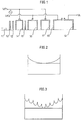
- FIG. 2 there is shown changes of the focusing voltage VF1 and the dynamic focusing voltage VF2 during the scan of the electron beam on the screen. And in FIG. 2, the voltage variation in the scanning of one field is illustrated.
- the lens intensity of the dynamic focusing gun namely the lens intensity of the horizontal and vertical aberration components of the electron beam with reference to FIG. 2 and 3
- a same voltage is applied to the first, third, fourth and fifth focusing electrode 14, 16, 17, 18 as depicted in FIG. 2 and 3, when the electron beam emitted from the cathode 11 of the gun, scans the central portion of the screen as shown in FIG. 4.
- the main lens intensity is weakened by ⁇ M, and the intensity of quadrapole lens formed between each forcusing electrodes 14-18 is changed by ⁇ Q.
- the resultant overall intensity T' of the dynamic lens becomes P+ ⁇ M+ ⁇ Q .
- the beam is deflected by the non-uniform magnetic field of the deflection yoke, it is vertically over-focused by ⁇ Y.
- the overall dynamic lens intensity T' and the focus intensity ⁇ Y by the non-uniform field are combined, to form a circular beam spot on the peripheral portion of the screen.
- an electron gun for a color picture ray tube having a triple electrodes part, a prefocusing lens part for preliminary focusing and accelerating the electron beam emittied from the triple electrodes part, and a main lens part for finally focusing and accelerating the beam passed through the prefocusing lens part, characterized in that: the prefocusing lens part comprises a plurality of focusing electrodes for forming at least one circular lens and at least one quadrapole lens; two different focusing voltages are selectively applied to each of focusing electrodes; and each of two focusing voltage is respectively dynamically changing synchronized with the deflection signal.
- the prefocusing lens part comprises the first to fifth focusing electrodes arranged successively from the triple electrodes, and two different focusing voltages, each of which is dynamically changing synchronized with the deflection signal, are respectively applied commonly to the first, third, fifth electrodes, and commonly to the the second, fourth electrodes.
- an electron gun for a color picture tube comprises: a triple electrodes part 20 constituted of a cathode 21 as a source of electron beam, a control electrode 22 thereof and a screen electrode 23; a prefocusing lens part 30 having the first to fifth focusing electrodes 31, 32, 33, 34, 35 being successively arranged from the screen electrode 23 for forming at least one circular lens and one quadrapole lens to preliminary focus and accelerate the electron beam emitted from the triple electrodes part 20; and a main lens part 40 having a final accelerating electrode 41 fabricated adjacent to the fifth focusing electrode 35.
- Respectively prescribed voltages are applied to each of electrodes constituting an electron gun, as follows.
- Two different focusing voltages F1, F2 are respectively applied commonly to the first, third and fifth focusing electrodes 31, 33, 35, and commonly to the second and fourth electrodes 32, 34.
- two dynamic voltages DF1, DF2 synchronized with the defelection signal are respectively added to each of focusing voltages F1, F2.
- An anode voltage VA of high level is applied to the final accelerating electrode 41.
- the higher level of two dynamic voltage DF1, DF2 is preferably twice of the lower level.
- focusing voltages F1, F2 and dynamic voltages DF1, DF2 applying to electrodes of the gun.
- 6200 and 7000V are respectively applied as two focusing voltages F1, F2; and 400 and 800V or 200 and 400V are respectively applied as two dynamic voltages DF1, DF2 which is synchronized with the deflection signal.
- numerals VF1, VF2 are respectively corresponded to sums of each of two focusing voltages F1, F2 and dynamic voltages DF1, DF2.
- FIG. 7 The change of dynamic focusing voltages VF1, VF2 during the scanning of a screen is shown in FIG. 7, and the change of focusing voltages during the scanning of one field is shown in FIG. 8.
- the lens intensity namely the intensity of the horizontal aberration components and the vertical aberration components are as follows.
- the focusing voltage F2 of 7000 V is applied to the first, third, and fifth focusing electrodes 31, 33, 35, and the focusing voltage F1 of 6,200 V is applied to the second, fourth focusing electrodes 32, 34.
- the potential difference of about 800V occurrs between each focusing electrodes to form circular or quadrapole lenses in the prefocusing lens part.
- the quadrapole lens formed in the prefocusing lens part has a negative aberration in which the horizontal beam is more intensively focused comparing with the vertical beam
- the main lens formed at the main lens part 40 has a positive aberration in which the vertical beam is more intensively focused than the horizontal beam, thus two lenses compensate each other to form the electron beams landed at the central portion of the screen to be circular.
- the quadrapole lens intensity Q recedes from the origin by ⁇ Q to be enhanced, thus the overall lens intensity T becomes to T+ ⁇ Q+ ⁇ M to form an asymmetrical lens when dynamic voltages DF1, DF2 are applied.
- the quadrapole lens intensity of the prefocusing lens part is enhanced, and the main lens intensity is weakened, thus the horizontal beam is just-focused in a optimal state and the vertical beam is under-focused at the central portion of the screen.
- the vertical beam is overfocused and horizontal beam is just-focused to form a circular beam spot also at the peripheral portion of the screen.
- the main lens has a positive aberration and the prefocusing lens has a negative aberration, to focus and acclerate the electron beam in multistage.
- the focusing characteristics are improved to provide a uniform beam section all over the screen, and accordingly a high definition tube can be obtained.
Landscapes
- Video Image Reproduction Devices For Color Tv Systems (AREA)
Applications Claiming Priority (2)
| Application Number | Priority Date | Filing Date | Title |
|---|---|---|---|
| KR9326167 | 1993-11-30 | ||
| KR1019930026167A KR970001591B1 (ko) | 1993-11-30 | 1993-11-30 | 칼라 음극선관용 전자총 |
Publications (1)
| Publication Number | Publication Date |
|---|---|
| EP0655765A1 true EP0655765A1 (fr) | 1995-05-31 |
Family
ID=19369661
Family Applications (1)
| Application Number | Title | Priority Date | Filing Date |
|---|---|---|---|
| EP94118718A Withdrawn EP0655765A1 (fr) | 1993-11-30 | 1994-11-28 | Canon à électrons pour tube image couleur |
Country Status (5)
| Country | Link |
|---|---|
| US (1) | US5754014A (fr) |
| EP (1) | EP0655765A1 (fr) |
| JP (1) | JPH0831337A (fr) |
| KR (1) | KR970001591B1 (fr) |
| CN (1) | CN1087486C (fr) |
Cited By (1)
| Publication number | Priority date | Publication date | Assignee | Title |
|---|---|---|---|---|
| WO2003019604A1 (fr) * | 2001-08-27 | 2003-03-06 | Koninklijke Philips Electronics N.V. | Tube a rayons cathodiques et dispositif d'affichage d'images |
Families Citing this family (8)
| Publication number | Priority date | Publication date | Assignee | Title |
|---|---|---|---|---|
| KR100377399B1 (ko) * | 1995-11-24 | 2003-06-19 | 삼성에스디아이 주식회사 | 칼라음극선관용전자총 |
| US6320333B1 (en) * | 1997-02-07 | 2001-11-20 | Matsushita Electric Industrial Co., Ltd. | Color picture tube |
| CN1326187C (zh) * | 2001-01-09 | 2007-07-11 | 株式会社东芝 | 阴极射线管装置 |
| KR100759544B1 (ko) * | 2001-09-24 | 2007-09-18 | 삼성에스디아이 주식회사 | 이중 다이나믹 포커스 전자총 |
| KR100823473B1 (ko) * | 2001-10-23 | 2008-04-21 | 삼성에스디아이 주식회사 | 빔 인덱스형 음극선관의 전자총 |
| JP2005322520A (ja) * | 2004-05-10 | 2005-11-17 | Matsushita Toshiba Picture Display Co Ltd | 陰極線管 |
| KR20130100630A (ko) * | 2012-03-02 | 2013-09-11 | 삼성전자주식회사 | 전자 방출 소자 및 이를 포함한 엑스선 발생 장치 |
| KR20140106291A (ko) * | 2013-02-26 | 2014-09-03 | 삼성전자주식회사 | 평판형 엑스선 발생기를 구비한 엑스선 영상 시스템, 엑스선 발생기 및 전자 방출소자 |
Citations (4)
| Publication number | Priority date | Publication date | Assignee | Title |
|---|---|---|---|---|
| US4825120A (en) * | 1986-10-22 | 1989-04-25 | Hitachi, Ltd. | Electron gun apparatus with auxiliary electrodes for a color cathode-ray tube |
| EP0366245A2 (fr) * | 1988-10-27 | 1990-05-02 | RCA Thomson Licensing Corporation | Système d'affichage en couleur et tube comportant un canon à électrons modulé sur deux électrodes |
| EP0440234A2 (fr) * | 1990-01-31 | 1991-08-07 | Samsung Display Devices Co., Ltd. | Canon à électrons pour un tube d'image en couleurs |
| DE4233955A1 (de) * | 1992-05-19 | 1993-11-25 | Samsung Electronic Devices | Elektronenkanone für eine Farbkathodenstrahlröhre |
Family Cites Families (5)
| Publication number | Priority date | Publication date | Assignee | Title |
|---|---|---|---|---|
| CN1040483C (zh) * | 1990-02-03 | 1998-10-28 | 三星电管株式会社 | 多级聚焦式电子枪中的电压提供方法 |
| JP3053845B2 (ja) * | 1990-06-07 | 2000-06-19 | 株式会社日立製作所 | 陰極線管 |
| DE69209125T2 (de) * | 1991-04-17 | 1996-10-02 | Philips Electronics Nv | Bildwiedergabeanordnung und Elektronenstrahlröhre |
| KR940010986B1 (ko) * | 1992-05-19 | 1994-11-21 | 삼성전관 주식회사 | 칼라 음극선관용 전자총 |
| KR950006601B1 (ko) * | 1992-08-12 | 1995-06-19 | 삼성전관주식회사 | 개선된 다이나믹 포커싱 전자총 |
-
1993
- 1993-11-30 KR KR1019930026167A patent/KR970001591B1/ko not_active Expired - Fee Related
-
1994
- 1994-11-28 EP EP94118718A patent/EP0655765A1/fr not_active Withdrawn
- 1994-11-29 CN CN94113072A patent/CN1087486C/zh not_active Expired - Fee Related
- 1994-11-29 JP JP6295396A patent/JPH0831337A/ja active Pending
- 1994-11-30 US US08/346,624 patent/US5754014A/en not_active Expired - Fee Related
Patent Citations (4)
| Publication number | Priority date | Publication date | Assignee | Title |
|---|---|---|---|---|
| US4825120A (en) * | 1986-10-22 | 1989-04-25 | Hitachi, Ltd. | Electron gun apparatus with auxiliary electrodes for a color cathode-ray tube |
| EP0366245A2 (fr) * | 1988-10-27 | 1990-05-02 | RCA Thomson Licensing Corporation | Système d'affichage en couleur et tube comportant un canon à électrons modulé sur deux électrodes |
| EP0440234A2 (fr) * | 1990-01-31 | 1991-08-07 | Samsung Display Devices Co., Ltd. | Canon à électrons pour un tube d'image en couleurs |
| DE4233955A1 (de) * | 1992-05-19 | 1993-11-25 | Samsung Electronic Devices | Elektronenkanone für eine Farbkathodenstrahlröhre |
Cited By (1)
| Publication number | Priority date | Publication date | Assignee | Title |
|---|---|---|---|---|
| WO2003019604A1 (fr) * | 2001-08-27 | 2003-03-06 | Koninklijke Philips Electronics N.V. | Tube a rayons cathodiques et dispositif d'affichage d'images |
Also Published As
| Publication number | Publication date |
|---|---|
| KR950015516A (ko) | 1995-06-17 |
| US5754014A (en) | 1998-05-19 |
| CN1087486C (zh) | 2002-07-10 |
| JPH0831337A (ja) | 1996-02-02 |
| CN1108797A (zh) | 1995-09-20 |
| KR970001591B1 (ko) | 1997-02-11 |
Similar Documents
| Publication | Publication Date | Title |
|---|---|---|
| US5449983A (en) | Color cathode ray tube apparatus | |
| KR950001842A (ko) | 다이내믹보정전압을 저감한 음극선관 | |
| EP0696049B1 (fr) | Tube à rayons cathodique couleur | |
| US5015910A (en) | Electron gun for color picture tube | |
| US5539285A (en) | Cathode-ray tube with electric field correction lens for improved resolution | |
| US4967120A (en) | Electron gun assembly of color ray tube | |
| EP0901146A2 (fr) | Tube à rayons cathodiques couleur | |
| US5754014A (en) | Electron gun for a color picture tube | |
| JP2000188068A (ja) | カラー陰極線管 | |
| US6624562B2 (en) | Color cathode ray tube having an improved electron gun | |
| US6339284B1 (en) | Color cathode ray tube apparatus having auxiliary grid electrodes | |
| US6614156B2 (en) | Cathode-ray tube apparatus | |
| KR940008156Y1 (ko) | 칼라 음극선관용 전자총 | |
| US6166483A (en) | QPF electron gun with high G4 voltage using internal resistor | |
| KR100377399B1 (ko) | 칼라음극선관용전자총 | |
| KR100219900B1 (ko) | 칼라음극선관용 전자총 | |
| US4469987A (en) | Means for enhancing brightness of a monochrome CRT without loss of resolution | |
| US6646381B2 (en) | Cathode-ray tube apparatus | |
| JP3672390B2 (ja) | カラー陰極線管用電子銃 | |
| US6819038B2 (en) | Double dynamic focus electron gun | |
| US6479951B2 (en) | Color cathode ray tube apparatus | |
| KR950000651B1 (ko) | 칼라 음극선관용 전자총 | |
| KR0142852B1 (ko) | 칼라 음극선관용 전자총 | |
| KR940008763B1 (ko) | 칼라 음극선관용 전자총 | |
| KR100646910B1 (ko) | 음극선관장치 |
Legal Events
| Date | Code | Title | Description |
|---|---|---|---|
| PUAI | Public reference made under article 153(3) epc to a published international application that has entered the european phase |
Free format text: ORIGINAL CODE: 0009012 |
|
| AK | Designated contracting states |
Kind code of ref document: A1 Designated state(s): CH DE ES FR GB IT LI NL |
|
| 17P | Request for examination filed |
Effective date: 19951127 |
|
| 17Q | First examination report despatched |
Effective date: 19961029 |
|
| STAA | Information on the status of an ep patent application or granted ep patent |
Free format text: STATUS: THE APPLICATION IS DEEMED TO BE WITHDRAWN |
|
| 18D | Application deemed to be withdrawn |
Effective date: 19970510 |