EP0655859B1 - Vorrichtung und Verfahren zur Datenverarbeitung - Google Patents
Vorrichtung und Verfahren zur Datenverarbeitung Download PDFInfo
- Publication number
- EP0655859B1 EP0655859B1 EP94307988A EP94307988A EP0655859B1 EP 0655859 B1 EP0655859 B1 EP 0655859B1 EP 94307988 A EP94307988 A EP 94307988A EP 94307988 A EP94307988 A EP 94307988A EP 0655859 B1 EP0655859 B1 EP 0655859B1
- Authority
- EP
- European Patent Office
- Prior art keywords
- resolution
- image data
- data
- recording
- scanning direction
- Prior art date
- Legal status (The legal status is an assumption and is not a legal conclusion. Google has not performed a legal analysis and makes no representation as to the accuracy of the status listed.)
- Expired - Lifetime
Links
Images


Classifications
-
- G—PHYSICS
- G06—COMPUTING OR CALCULATING; COUNTING
- G06T—IMAGE DATA PROCESSING OR GENERATION, IN GENERAL
- G06T3/00—Geometric image transformations in the plane of the image
- G06T3/40—Scaling of whole images or parts thereof, e.g. expanding or contracting
-
- H—ELECTRICITY
- H04—ELECTRIC COMMUNICATION TECHNIQUE
- H04N—PICTORIAL COMMUNICATION, e.g. TELEVISION
- H04N1/00—Scanning, transmission or reproduction of documents or the like, e.g. facsimile transmission; Details thereof
- H04N1/40—Picture signal circuits
- H04N1/40068—Modification of image resolution, i.e. determining the values of picture elements at new relative positions
Definitions
- This invention relates to a data processing method and apparatus in which processing of converting resolution is performed for image data.
- facsimile apparatuses in which a recording system having a resolution different from that of an image received through facsimile communication is used, have been practically used.
- a printer interface is provided, and a recording unit can be used as a printer for an external information processing apparatus, such as a computer or the like.
- resolution conversion must be performed when the reading resolution of an image received through facsimile communication or a copied image differs from the resolution of the recording unit.
- a main control unit of a facsimile apparatus (hereinafter termed a “facsimile control unit") adjusts resolution by repeatedly transmitting image data for one line to the recording unit a plurality of times.
- FIG. 9 is a diagram illustrating resolution conversion in the main scanning direction and the sub-scanning direction in a facsimile apparatus.
- the ratio of the resolution of a read or received image to the resolution in a recording operation is as follows:
- a resolution conversion circuit is required because an image must be recorded with the same magnification as that of an original during a reception or copying operation. If original data is developed from 9 bits into 16 bits in the main scanning direction, and from 6 bits into 11 bits in the sub-scanning direction, the magnification is as follows:
- FIG. 9 briefly illustrates the concept of resolution conversion when a read image is copied or a received image is recorded.
- reference numeral 50a represents resolution conversion in the main scanning direction.
- Reference numeral 50b represents resolution conversion in the sub-scanning direction. By replacing read or received pixels for one line 51b by recorded pixels for two lines 51b', and pixels 53b by recorded pixels for one line 53b', unit-magnification recording in the sub-scanning direction can be performed.
- the main control unit transmits image data for the same line to the recording unit a plurality of (two) times with a predetermined ratio.
- the entire amount of data transmitted to the recording unit further increases if image data for one line is trasmitted a plurality of times.
- An increase in the amount of transmitted data causes an increase in the data transmission time, thereby causing an increase in the time required for outputting a received or copied image.
- the present invention has been made in consideration of the above-described problems.
- United States Patent Specification No US-A-4841375 discloses image resolution conversion apparatus incorporating a pixel conversion ratio setter which converts the resolution of input data from one resolution to a second resolution in accordance with ratios pre-set by the pixel ratio conversion setter.
- United States Patent Specification US-A-4 536 802 discloses a facsimile apparatus in which the transmitted image is partially or totally enlarged at the receiving unit thereof. Enlargement processing in the sub-scanning direction can be performed in the transmission side facsimile unit.
- FIG. 1 is a cross-sectional view illustrating a facsimile apparatus of the embodiment.
- a reading unit A optically reads an original.
- a recording unit B comprises an ink-jet recorder.
- a sheet-feeding unit C supplies the recording unit B with sheets of recording paper, comprising cut sheets, mounted on a recording-paper cassette while individually separating sheets of the recording paper.
- a conveying path for the sheet is indicated by symbol G.
- the uppermost sheet of recording paper 12 mounted in a recording-paper cassette 50 is picked up by a sheet-feeding roller 51 and separation pawls 52, and is conveyed to the recording unit by a conveying roller 5.
- recording is performed by performing main scanning by reciprocating a recording head 1 in directions perpendicular to the plane of FIG. 1 by a carriage.
- the sheet is discharged by a sheet-discharging roller 9, and is mounted on a discharged-sheet stacker 53.
- a photosensor 13 is disposed on the shaft of the sheet-discharging roller 9. The photosensor 13 detects exhaustion of ink in the recording head 1, as well as sheet jams in the vicinity of the sheet-discharging roller 9, by detecting the density of a footer pattern printed on a trailing-end portion of the sheet.
- the recording head 1 is shown.
- a cartridge-type ink-jet recording head which incorporates an ink tank and which can be replaced by a new head when ink is exhausted, is used as the recording head 1.
- the recording head 1 has a resolution of 360 dpi, and includes 64 nozzles.
- the ink is discharged from a discharging port provided at the distal end of each nozzle due to the pressure of film boiling produced in the ink by being heated by an electrothermal transducer provided within the nozzle.
- a carriage 2 reciprocates the recording head 1 in directions orthogonal to the conveying direction of the recording paper 12 (the sub-scanning direction), i.e., the main scanning direction.
- the carriage 2 is slidably held by a guide bar 11 and a contact unit 2a.
- the carriage 2 is reciprocated by a pulley 4 driven by a carriage motor (not shown), and a timing belt 3. At that time, a printing signal and electric power are supplied from an electric circuit of the main body of the apparatus to the recording head 1 via a flexible cable 7.
- Reference numeral 15 represents a cap which operates as ink-receiving means.
- the cap 15 is provided at a position corresponding to a position where the carriage 2 assumes a standby state (a home position), and moves vertically whenever necessary. When the cap 15 is raised, it is in close contact with the recording head 1, so as to cover the nozzle portion and thereby to prevent evaporation of ink and adhesion of dust.
- a carriage home sensor 10 provided in the main body of the apparatus, and a light-blocking plate 2b provided on the carriage 2 are used.
- the carriage home sensor 10 comprises a transmission photo-interrupter, which detects that the recording head 1 and the cap 15 face each other by utilizing the fact that when the carriage 2 has moved to the standby position, light emitted from a portion of the carriage home sensor 10 is interrupted by the light-blocking plate 2b.
- the sheet of the recording paper 12 is fed upward from below in FIG. 2, is then bent in the horizontal direction by the conveying roller 5 and a sheet guide 6, and is conveyed in a direction indicated by arrow H (the sub-scanning direction).
- the conveying roller 5 and the sheet-discharging roller 9 are driven by respective driving systems (not shown), to convey the sheet of the recording paper 12 in the sub-scanning direction with high accuracy linked with the reciprocating movement of the carriage 2 whenever necessary.
- Each of spurs 8 is made of a material having a high water-repellent property, and contacts the sheet of the recording paper 12 only at its edge-shaped circumferential portion.
- the spurs 8 are disposed separated from each other by a predetermined length by bearing members (not shown), and are configured so as to guide and convey the sheet of the recording paper 12 without influencing an image on the sheet even if the spurs 8 contact unfixed ink on the sheet immediately after the image has been printed.
- a photosensor 13 comprises a reflection-type photo-interrupter, which is disposed on the shaft of the sheet-discharging roller 9 and optically detects the presence of a predetermined pattern (a black mark) printed on the sheet. The photosensor 13 can determine exhaustion of ink in the recording head 1 and a sheet jam based on the output of the black mark and an output representing a white portion of the sheet of the recording paper.
- the photosensor 13 used in the present embodiment comprises a red LED (light-emitting diode), serving as a light-emitting device, and a phototransistor, serving as a photosensing device, and can determine whether a range within a circle having a diameter of 3 mm is white or black.
- a portion of the sheet-discharging roller 9 facing the photosensor is made of black rubber.
- FIG. 3 is a block diagram illustrating the electric configuration of the facsimile apparatus shown in FIGS. 1 and 2.
- reference numeral 101 represents a facsimile control unit comprising a microprocessor and the like.
- the facsimile control unit 101 comprises a CPU (central processing unit) 104, a ROM (read-only memory) 103, a RAM (random access memory) 102, and the like, and controls image input/output operations and the entire communication processing.
- the ROM 103 stores control programs.
- the RAM 102 is used, for example, as a work area for the CPU 104, and as a buffer for image data (an image buffer).
- the image input and output operations are performed by a reading unit 100 and a recording unit 111. That is, image data is read by the reading unit 100, which comprises a CCD (charge-coupled device) sensor, an original-conveying system, and the like. Received image data, or image data read by the reading unit 100 during a copying operation is printed on paper by the recording unit 111, which comprises the above-described ink-jet printer.
- the reading unit 100 which comprises a CCD (charge-coupled device) sensor, an original-conveying system, and the like.
- Received image data, or image data read by the reading unit 100 during a copying operation is printed on paper by the recording unit 111, which comprises the above-described ink-jet printer.
- Connection and data input/output operations with a communication network are performed by a modem 105 and an NCU (network control unit) 106.
- a telephone set for communication and manual control, and the like are connected to the NCU 106.
- the recording unit 111 comprises an ink-jet head, a carriage, recording-paper conveying means, control means and the like.
- the control means includes a CPU 114, a ROM 113 for storing control programs for the CPU 114 and character patterns, and a RAM 112 used as a work area for the CPU 114, a reception buffer and a printing buffer.
- a switch 110 is switched between a facsimile mode and a printer mode by the control of the facsimile control unit 101. If the switch 110 is switched to side "a”, the facsimile mode is provided, and data received through facsimile communication is transmitted to the recording unit, where the data is printed. If the switch 110 is switched to side "b", a printer mode is provided, and printing data from an external information processing apparatus connected to a connector 115 is transmitted to the recording unit, where the data is printed. When the switch is switched to side "b", a terminal c is also connected.
- a command from the connector 115 is thereby input to the facsimile control unit 101 through the switch 110, so that the facsimile control unit 101 can detect the transmission of the command from the connector 115 to the recording unit when the switch 110 is switched to side 'b'.
- a FAX operation unit 108 and a recording-unit operation unit 109 are provided on an operation panel 107.
- Ten keys for inputting telephone numbers, various kinds of function keys, an operation-mode key for switching the operation mode between the facsimile mode and the printer mode, a display device used for displaying, for example, a telephone number or time, and the like are provided on the FAX operation unit 108.
- the recording-unit operation unit 109 includes a display unit for displaying the current operation mode.
- the recording unit has two operation modes, i.e., a mode of recording an image received through facsmile communication or a copied image (hereinafter termed a "facsimile mode"), and a mode of recording data from the external information processing apparatus (hereinafter termed a "printer mode"). Selection between the facsimile mode and the printer mode is performed through the operation-mode key within the FAX operation unit 108.
- the recording unit 111 must identify whether received data comprises image data received through facsimile communication or data from the external information processing apparatus. That is, in the facsimile mode, the recording unit 111 must perform resolution conversion in the sub-scanning direction. Accordingly, the facsimile control unit 101 transmits a particular command to the recording unit 111 in accordance with an input from the operation-mode key within the FAX operation unit 108, to set the recording unit 111 to the facsimile mode.
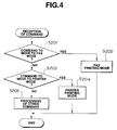
- FIG. 4 is a flowchart illustrating the operation of the recording unit 111.
- a program corresponding to this flowchart is stored in the ROM 113, and the CPU 114 performs control in accordance with this program.
- step S201 it is determined if the transmitted command is a command to move to the facsimile mode. If the result of the determination is affirmative, the process proceeds to step S202. In step S202, the operation mode of the recording unit is set to a facsimile printing mode, and the operation of receiving the command is terminated. If the result of the determination in step S201 is negative, the process proceeds to step S203. In step S203, it is determined if the received command is a command to move to the printer mode. If the result of the determination is affirmative, the process proceeds to step S204, where a printer printing mode is set, and the process is terminated. If the result of the determination in step S203 is negative, the process proceeds to step S205, where the received command is processed, and the process is terminated.
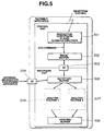
- FIG. 5 is a block diagram illustrating the configuration of a system of data handling of the facsimile apparatus.
- Image data received from the facsimile control unit 101 or obtained during a copying operation is subjected to resolution conversion 301 in the main scanning direction (the direction of lines) (after performing decoding processing and the like for received image data).
- the original 9-bit data is converted into 16-bit data in order to convert the resolution into the resolution 360 dpi of the recording unit.
- this processing is executed by program processing of the CPU 104 within the facsimile control unit 101.
- a control table which controls the number of copying operations for each line of the data so as to be adjusted to the resolution of the recording unit in the sub-scanning direction in accordance with the resolution of the data in the sub-scanning direction, determines the number of copying operations for each line of the data.
- the obtained data relating to the number of copying operations is added to the image data as one of commands for performing various controls for the recording unit, and the resultant data is stored in an image buffer 302.
- an image buffer 302. As shown in FIG. 9, in resolution conversion in the sub-scanning direction, if, for example, the resolution of the image data in the sub-scanning direction equals 7.7 lines/mm, 6-bit data must be developed into 11-bit data in order to be converted into 360 dpi.
- the control table stores the line number and the number of copying operations of image data so as to correspond to each other in order to execute the above-described resolution conversion, and these data are stored in a predetermined region of the ROM 103. Data transfer between the facsimile control unit 101 and the recording unit 111 is performed via an interface (here, a Centronix interface) 303.
- the recording unit includes a reception buffer 305 for storing data to which a control command is added (hereinafter termed "command data") transmitted from the facsimile control unit or the external information processing apparatus via the interface 303.
- the command data stored in the reception buffer 305 is processed by an analysis routine 1 306 or an analysis routine 2 307 if the recording unit 111 is set to the printer mode or to the facsimile mode, respectively, and only printing data to be actually printed is developed in a printing buffer 308.
- the analysis routines 1 and 2 are executed by program processing of the CPU 114.
- the printing buffer 308 can store the amount of data recorded by a single main scanning operation of the recording head 1. In the present embodiment, the printing buffer 308 has a storage capacity of 64 x 3648 bits.
- Resolution conversion in the sub-scanning direction is executed when the recording unit 111 is set to the facsimile mode.
- image data for one line transmitted from the facsimile control unit 101 is developed into data for a plurality of lines in the printing buffer 308.
- the facsimile control unit 101 must add a particular control command indicating the number of lines on which the recording unit must develop the image data for one line in the printing buffer 308 (hereinafter termed a "line-copying command").
- the recording unit which has received command data, analyzes the command by the particular command routine 2 (307) used when setting the facsimile mode, and develops the data on lines, whose number has been indicated by the command, in the printing buffer 308.
- FIG. 6 is a flowchart illustrating line-copying processing for image data for one line.
- a program corresponding to this flowchart is stored in the ROM 113, and the CPU 114 performs control in accordance with this program.
- step S401 When the result of the analysis of the received command indicates that "image data for one line must be copied on n lines", the data is stored in the printing buffer 308 in step S401.
- step S402 a count number line_cnt, indicating the number of lines on which the image data is stored in the printing buffer 308, is incremented.
- step S403 the assigned copying number of lines is compared with the number line_cnt. If the number line_cnt equals at least the assigned copying number of lines, the storage of the data is completed. If the number line_cnt is less than the assigned copying number of lines, the process proceeds to step S404, where the address in which data of the next line in the printing buffer 308 must be stored is calculated, and the process returns to step S401.
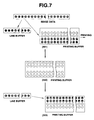
- FIG. 7 illustrates a case in which the recording unit 111 includes a region for storing data in addition to the printing buffer 308, i.e., a line buffer for one line.
- the data is also stored in the line buffer as well as in the printing buffer 308.
- the processing is temporarily interrupted.
- image data for two lines has been subjected to line-copying processing (501).
- the data in the printing buffer 308 is printed, and the contents of the printing buffer 308 are cleared (502). Thereafter, the line-copying processing is resumed.
- data is read from the line buffer and is developed in the printing buffer 308 (503).
- new data is stored in the line buffer, line-copying processing is performed, and the data is developed in the printing buffer 308.
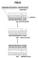
- FIG. 8 illustrates a case in which the recording unit 111 does not have a line buffer as shown in FIG. 7.
- the facsimile apparatus which can also be used as the printer of the external information processing apparatus, resolution conversion is performed by executing line-copying processing by the recording unit 111.
- the amount of data transfer from the facsimile control unit 101 to the recording unit 111 can be reduced, thereby causing a decrease in the data transfer time.
- the recording time can be reduced.
- the disclosed principle can be applied to any of so-called on-demand type and continuity type, but is more effectively applied to the on-demand type, because in this type, by applying at least one driving signal for providing an electrothermal transducer, disposed facing a sheet or a liquid channel where a liquid (ink) is held, with abrupt temperature rise to cause film boiling in accordance with recording information, thermal energy is generated in the electrothermal transducer, thereby causing film boiling in a heat-acting surface of a recoding head to form a bubble in the liquid (ink) in one-to-one correspondence to the driving signal.
- the liquid (ink) is discharged from a discharging aperture by the growth and contraction of the bubble to form at least one droplet. It is preferable to provide the driving signal in the form of a pulse, because a bubble can be instantaneously and appropriately grown and contracted, and the liquid can be discharged at a high response speed.
- Driving signals described in U.S. Patents Nos. 4,463,359 and 4,345,262 are suitable for the pulse-shaped driving signal. Better recording can be performed if conditions relating to the rate of temperature rise of the above-described heat-acting surface described in U.S. Patent No. 4,313,124 are adopted.
- configurations of the recording head in addition to configurations obtained by combining a discharging port, a liquid channel and electrothermal transducers (a linear liquid channel or an orthogonal liquid channel) disclosed in the above-described patent specifications, configurations, in which a heat-acting surface is disposed at a curved region, disclosed in U.S. Patents Nos. 4,558,333 and 4,459,600, may also be adopted.
- a configuration, in which a common slit is used as a discharging unit of a plurality of electrothermal transducers, disclosed in Japanese Patent Laid-Open Application (Kokai) No. 59-123670 (1984), or a configuration, in which an aperture for absorbing the pressure wave of thermal energy is provided so as to correspond to a discharging unit, disclosed in Japanese Patent Laid-Open Application (Kokai) No. 59-138461 (1984), may also be adopted.
- any of a configuration, in which the length is covered by combining a plurality of recording heads as described in the foregoing patent specifications, and a configuration, in which the length is covered by an single integrated recording head, may be adopted.
- the present invention is also effective even if an exchangeable chip-type recording head, in which electrical connection with the main body of the apparatus and ink supply from the main body of the apparatus can be performed by being mounted in the main body of the apparatus, or a cartridge-type recording head, in which an ink tank is provided as one body with the recording head, is used.
- recovery means Prefferably to add recovery means, preliminary auxiliary means and the like for the recording head, because the effects of the present invention are further stabilized. More specifically, the provision of capping means, cleaning means, and pressing or attraction means for the recording head, and preliminary heating means comprising electrothermal transducers, another heating elements, or combination of these units, and the provision of a preliminary discharging mode for performing a discharging operation different from a discharging operation for recording are effective for performing stable recording.
- the apparatus may use not only a recording mode of a single main color, such as black or the like, but also at least one of a recording mode of a plurality of different colors, and a full-color recording mode obtained by color mixing, by using a single integrated recording head or combination of a plurality of recording heads.
- the ink is liquid.
- the ink may solidify at a temperature equal to or lower than the room temperature, and may soften or be liquidified at the room temperature.
- the temperature of the ink is generally adjusted within a range between 30 °C and 70 C so as to maintain the viscosity of the ink within a stable discharging range. Accordingly, it is only necessary that the ink is liquid when a recording signal is provided.
- ink which solidifies in an unused state, and which is liquidified by thermal energy provided by a recording signal and is discharged in the form of a liquid droplet, and solidifies when the droplet reaches a recording medium, may be used.
- ink may be held in recesses or threaded holes of a porous sheet in a liquid state or a solid state so as to face electrothermal transducers.
- the above-described film boiling method is most effective for the above-described ink.
- the recorder of the present invention may comprise not only the above-described facsimile apparatus, but also an image output terminal integrated with or separated from an information processing apparatus, such as a word processor, a computer or the like, or a copier combined with a reader or the like.
- the present invention by adding information for resolution conversion to image data and transmitting the resultant data from data transmission means, resolution conversion of the image data is performed at the side of data processing means while performing copying processing. Hence, the data transfer time can be shortened compared with a case in which resolution conversion of image data is performed at the side of the data transmission means, and data is repeatedly transmitted to the data processing means.
- the recording time can be shortened.
Landscapes
- Engineering & Computer Science (AREA)
- Physics & Mathematics (AREA)
- General Physics & Mathematics (AREA)
- Theoretical Computer Science (AREA)
- Multimedia (AREA)
- Signal Processing (AREA)
- Editing Of Facsimile Originals (AREA)
- Fax Reproducing Arrangements (AREA)
- Ink Jet (AREA)
- Accessory Devices And Overall Control Thereof (AREA)
- Record Information Processing For Printing (AREA)
Claims (17)
- Faksimilevorrichtung mit:einer Datenübertragungseinrichtung (101) zur Übertragung von Bilddatenzeilen zu einer Datenverarbeitungseinrichtung (111), die im Betrieb die Auflösung der Bilddaten von einer ersten Auflösung zu einer zweiten Auflösung, die höher als die erste Auflösung ist, umwandelt und eine Verarbeitung der Bilddaten derart ausführt, dass die Bilddaten mit der zweiten Auflösung aufgezeichnet werden können, wobei die Datenübertragungseinrichtung die Auflösungsumwandlung in der die Hauptabtastrichtung darstellenden Zeilenrichtung durchführt und mittels der Datenübertragungseinrichtung Bilddatenzeilen und hinzugefügte Befehlsinformation zur Umwandlung der Auflösung der Bilddaten in eine zu der Zeilenrichtung senkrechte Unterabtastrichtung zu der Datenverarbeitungseinrichtung (111) übertragbar sind, und wobei die Datenverarbeitungseinrichtung dahingehend ausgestaltet ist, Zeilen der empfangenen Bilddaten mehrfach zu kopieren, wie dies gemäß dem von der Befehlsinformation ermittelten Unterschied zwischen der ersten Auflösung und der zweiten Auflösung eingestellt ist, um die Auflösung der Zeilendaten in der senkrechten Richtung in die zweite Auflösung umzuwandeln.
- Vorrichtung nach Anspruch 1, wobei die Datenübertragungseinrichtung dahingehend ausgestaltet ist, über ein Netzwerk übertragene Bilddaten zu empfangen und den empfangenen Bilddaten entsprechende Bilddatenzeilen an die Datenverarbeitungseinrichtung zu übertragen.
- Vorrichtung nach zumindest einem der vorstehenden Ansprüche, mit:einer Aufzeichnungseinrichtung (111) zur Durchführung einer Aufzeichnung mit den von der Datenverarbeitungseinrichtung verarbeiteten und umgewandelten Bilddaten auf einem Aufzeichnungsmaterial.
- Vorrichtung nach zumindest einem der vorstehenden Ansprüche, wobei die Datenübertragungseinrichtung eine Leseeinrichtung (100) zum Lesen eines Bildes umfasst und wobei die von der Leseeinrichtung gelesenen Bilddaten zu der Datenverarbeitungseinrichtung übertragen werden.
- Vorrichtung nach Anspruch 3 oder 4, mit:einer Eingabeeinrichtung (115) zur Eingabe von Bilddaten, die von einer externen Informationsverarbeitungsvorrichtung zu der Datenverarbeitungsvorrichtung ausgegeben werden; undeiner Schalteinrichtung (110) zur Umschaltung der Eingabe an die Datenverarbeitungseinrichtung zwischen der Datenübertragungseinrichtung und der Eingabeeinrichtung.
- Vorrichtung nach Anspruch 3 und den Ansprüchen 4 oder 5, bei Abhängigkeit von Anspruch 3, wobei die Aufzeichnungseinrichtung im Betrieb eine Aufzeichnung durch Bewegung eines Aufzeichnungskopfes mit einer Vielzahl von Aufzeichnungselementen in der Hauptabtastrichtung bezogen auf ein Aufzeichnungsmaterial, durchführt, und wobei das Aufzeichnungsmaterial bezogen auf den Aufzeichnungskopf in der Unterabtastrichtung bewegt wird, nachdem jede Hauptabtastung beendet ist.
- Vorrichtung nach Anspruch 6, wobei die Vielzahl von Aufzeichnungselementen in der Unterabtastrichtung mit einem der zweiten Auflösung entsprechenden Abstand angeordnet sind.
- Vorrichtung nach den Ansprüchen 6 und 7, wobei der Aufzeichnungskopf im Betrieb ein Tintentröpfchen ausstößt, indem er eine Änderung des Tintenzustands unter Verwendung von durch die Aufzeichnungselemente erzeugter Ausstoßenergie herbeiführt.
- Vorrichtung nach zumindest einem der vorstehenden Ansprüche, wobei die Übertragungseinrichtung in die Faksimilevorrichtung eingebaut ist.
- Faksimiledatenverarbeitungsverfahren mit den Schritten:Übertragen von Bilddatenzeilen durch eine Datenübertragungseinrichtung (101) zu einer Datenverarbeitungseinrichtung (111), die die Auflösung der Bilddaten von einer ersten Auflösung zu einer zweiten Auflösung, die höher als die erste Auflösung ist, umwandelt und eine Verarbeitung der Bilddaten so ausführt, dass die Bilddaten mit der zweiten Auflösung aufgezeichnet werden können, Durchführen der Auflösungsumwandlung in der die Hauptabtastrichtung darstellenden Zeilenrichtung durch die Datenübertragungseinrichtung, Übertragen von Bilddatenzeilen und hinzugefügter Befehlsinformation zur Umwandlung der Auflösung der Bilddaten in einer zu der die Unterabtastrichtung darstellenden Zeilenrichtung senkrechten Richtung zu der Datenverarbeitungseinrichtung (111) durch die Datenübertragungseinrichtung, mehrfaches Kopieren von Zeilen der empfangenen Bilddaten gemäß dem von der Befehlsinformation ermittelten Unterschied zwischen der ersten Auflösung und der zweiten Auflösung durch die Datenverarbeitungseinrichtung zum Umwandeln der Auflösung der Zeilendaten in der senkrechten Richtung in die zweite Auflösung.
- Verfahren nach Anspruch 10, mit den Schritten zum Empfangen von über ein Netzwerk übertragenen Bilddaten und Übertragen von den den empfangenen Bilddaten entsprechenden Bilddatenzeilen zu der Datenverarbeitungseinrichtung.
- Verfahren nach den Ansprüchen 10 oder 11, mit dem Schritt zum
Aufzeichnen der umgewandelten und verarbeiteten Bilddaten auf ein Aufzeichnungsmaterial. - Verfahren nach einem der Ansprüche 10 bis 12, mit den Schritten zum Lesen eines Bildes und Übertragen der gelesenen Bilddaten zu der Datenverarbeitungseinrichtung.
- Verfahren nach Anspruch 12 oder 13, mit den Schritten
Eingeben von von einer externen Informationsverarbeitungsvorrichtung ausgegebenen Bilddaten über eine Eingabeeinrichtung in die Datenverarbeitungseinrichtung; und
Schalten der Eingabe in die Datenverarbeitungseinrichtung zwischen der Datenübertragungseinrichtung und der Eingabeeinrichtung. - Verfahren nach Anspruch 12 und den Ansprüchen 13 oder 14, bei Abhängigkeit von Anspruch 12, wobei der Aufzeichnungsvorgang durch ein Bewegen eines Aufzeichnungskopfes durchgeführt wird, an dem eine Vielzahl von Aufzeichnungselementen in einer Hauptabtastrichtung bezogen auf ein Aufzeichnungsmaterial angeordnet sind, und das Aufzeichnungsmaterial bezogen auf den Aufzeichnungskopf nach Beendigung jeder Hauptabtastung in eine Unterabtastrichtung bewegt wird.
- Verfahren nach Anspruch 15, wobei die Vielzahl von Aufzeichnungselementen in der Unterabtastrichtung mit einem der zweiten Auflösung entsprechenden Abstand angeordnet ist.
- Verfahren nach den Ansprüchen 15 und 16, wobei der Aufzeichnungskopf im Betrieb Tintentröpfchen ausstößt, indem er eine Änderung des Tintenzustands unter Verwendung von durch Aufzeichnungselemente erzeugte Ausstoßenergie herbeiführt.
Applications Claiming Priority (3)
| Application Number | Priority Date | Filing Date | Title |
|---|---|---|---|
| JP29536893A JP3337792B2 (ja) | 1993-11-25 | 1993-11-25 | データ処理装置及び記録装置及びデータ処理方法 |
| JP295368/93 | 1993-11-25 | ||
| JP29536893 | 1993-11-25 |
Publications (3)
| Publication Number | Publication Date |
|---|---|
| EP0655859A2 EP0655859A2 (de) | 1995-05-31 |
| EP0655859A3 EP0655859A3 (de) | 1995-10-11 |
| EP0655859B1 true EP0655859B1 (de) | 2003-01-22 |
Family
ID=17819727
Family Applications (1)
| Application Number | Title | Priority Date | Filing Date |
|---|---|---|---|
| EP94307988A Expired - Lifetime EP0655859B1 (de) | 1993-11-25 | 1994-10-31 | Vorrichtung und Verfahren zur Datenverarbeitung |
Country Status (5)
| Country | Link |
|---|---|
| US (1) | US5732196A (de) |
| EP (1) | EP0655859B1 (de) |
| JP (1) | JP3337792B2 (de) |
| DE (1) | DE69432045T2 (de) |
| ES (1) | ES2188606T3 (de) |
Families Citing this family (12)
| Publication number | Priority date | Publication date | Assignee | Title |
|---|---|---|---|---|
| JPH09275488A (ja) * | 1996-04-08 | 1997-10-21 | Brother Ind Ltd | 画像読取装置 |
| JPH10257289A (ja) * | 1997-03-11 | 1998-09-25 | Murata Mach Ltd | ファクシミリ装置 |
| JPH11203101A (ja) * | 1998-01-19 | 1999-07-30 | Riso Kagaku Corp | コンピュータ・インターフェース装置および孔版印刷機用出力データの作成方法 |
| US6469800B1 (en) * | 1999-12-07 | 2002-10-22 | Destiny Technology Corporation | Method for converting vertical resolutions to printer-based resolutions |
| US6894804B2 (en) * | 2001-10-03 | 2005-05-17 | Toshiba Tec Kabushiki Kaisha | Method to dynamically perform document layout functions |
| US7133152B2 (en) | 2002-02-28 | 2006-11-07 | Kabushiki Kaisha Toshiba | Post RIP paper conversion |
| US7164492B2 (en) * | 2002-03-07 | 2007-01-16 | Kabushiki Kaisha Toshiba | Automatic facsimile document resizing |
| US7245392B2 (en) | 2002-03-08 | 2007-07-17 | Kabushiki Kaisha Toshiba | Method for generating a fax cover page |
| WO2003084222A1 (en) * | 2002-04-02 | 2003-10-09 | Matsushita Electric Industrial Co., Ltd. | Printing control device and printing control method |
| US8154759B2 (en) * | 2007-05-15 | 2012-04-10 | Ricoh Company, Ltd. | Image forming apparatus, image forming method and computer readable information recording medium |
| JP4896051B2 (ja) * | 2007-05-15 | 2012-03-14 | 株式会社リコー | 画像形成装置、画像形成方法及びプログラム |
| JP7495830B2 (ja) * | 2020-06-26 | 2024-06-05 | 東芝テック株式会社 | 画像処理装置及び画像形成装置 |
Citations (1)
| Publication number | Priority date | Publication date | Assignee | Title |
|---|---|---|---|---|
| US4536802A (en) * | 1982-01-08 | 1985-08-20 | Fuji Xerox Co., Ltd. | Facsimile apparatus |
Family Cites Families (13)
| Publication number | Priority date | Publication date | Assignee | Title |
|---|---|---|---|---|
| CA1127227A (en) * | 1977-10-03 | 1982-07-06 | Ichiro Endo | Liquid jet recording process and apparatus therefor |
| US4330787A (en) * | 1978-10-31 | 1982-05-18 | Canon Kabushiki Kaisha | Liquid jet recording device |
| US4345262A (en) * | 1979-02-19 | 1982-08-17 | Canon Kabushiki Kaisha | Ink jet recording method |
| US4463359A (en) * | 1979-04-02 | 1984-07-31 | Canon Kabushiki Kaisha | Droplet generating method and apparatus thereof |
| US4313124A (en) * | 1979-05-18 | 1982-01-26 | Canon Kabushiki Kaisha | Liquid jet recording process and liquid jet recording head |
| US4558333A (en) * | 1981-07-09 | 1985-12-10 | Canon Kabushiki Kaisha | Liquid jet recording head |
| JPS59138461A (ja) * | 1983-01-28 | 1984-08-08 | Canon Inc | 液体噴射記録装置 |
| JPS6071260A (ja) * | 1983-09-28 | 1985-04-23 | Erumu:Kk | 記録装置 |
| US4814890A (en) * | 1984-11-19 | 1989-03-21 | Canon Kabushiki Kaisha | Image communicating system |
| JPS62178069A (ja) * | 1986-01-31 | 1987-08-05 | Toshiba Corp | フアクシミリ記録方式 |
| US4841375A (en) * | 1986-05-29 | 1989-06-20 | Kabushiki Kaisha Toshiba | Image-resolution conversion apparatus for converting a pixel-density of image data |
| JPH03259657A (ja) * | 1990-03-08 | 1991-11-19 | Canon Inc | ファクシミリ装置 |
| DE59107510D1 (de) * | 1990-12-04 | 1996-04-11 | Siemens Ag | Verfahren zum Umsetzen von Bilddaten für Faksimiledruckwerke mit unterschiedlichen Auflösungen |
-
1993
- 1993-11-25 JP JP29536893A patent/JP3337792B2/ja not_active Expired - Fee Related
-
1994
- 1994-10-31 ES ES94307988T patent/ES2188606T3/es not_active Expired - Lifetime
- 1994-10-31 EP EP94307988A patent/EP0655859B1/de not_active Expired - Lifetime
- 1994-10-31 DE DE69432045T patent/DE69432045T2/de not_active Expired - Lifetime
- 1994-11-03 US US08/335,371 patent/US5732196A/en not_active Expired - Lifetime
Patent Citations (1)
| Publication number | Priority date | Publication date | Assignee | Title |
|---|---|---|---|---|
| US4536802A (en) * | 1982-01-08 | 1985-08-20 | Fuji Xerox Co., Ltd. | Facsimile apparatus |
Also Published As
| Publication number | Publication date |
|---|---|
| EP0655859A2 (de) | 1995-05-31 |
| JP3337792B2 (ja) | 2002-10-21 |
| JPH07154589A (ja) | 1995-06-16 |
| ES2188606T3 (es) | 2003-07-01 |
| US5732196A (en) | 1998-03-24 |
| DE69432045T2 (de) | 2003-10-09 |
| DE69432045D1 (de) | 2003-02-27 |
| EP0655859A3 (de) | 1995-10-11 |
Similar Documents
| Publication | Publication Date | Title |
|---|---|---|
| US6048045A (en) | Printer and facsimile apparatus that can test for a proper functioning ink jet nozzle without printing a test pattern | |
| EP0655859B1 (de) | Vorrichtung und Verfahren zur Datenverarbeitung | |
| US5832190A (en) | Image recording apparatus with reliable, efficient and power-saving stand-by state | |
| US5689289A (en) | Image recording apparatus | |
| EP0655854B1 (de) | Bildübertragungsgerät | |
| US6426805B1 (en) | Image recording apparatus and method therefor | |
| US6937360B1 (en) | Image forming method and apparatus which can perform output operation suitable for received image and communication apparatus using the same | |
| US5731882A (en) | Image communication apparatus | |
| KR19990038520A (ko) | 셔틀방식 복합기의 인쇄오차 보정방법 | |
| EP0608880B1 (de) | Bilderzeugungsgerät | |
| US5911526A (en) | Printing apparatus | |
| US7405839B2 (en) | Printing apparatus printer driver, and buffer management method | |
| US5822076A (en) | Facsimile apparatus with ink cartridge and residual ink detection function | |
| US5485285A (en) | Image recording apparatus | |
| US5943068A (en) | Printer, facsimile apparatus using printer and image processing apparatus | |
| EP0522701B1 (de) | Farbbildaufzeichnungsverfahren und -gerät | |
| US6201615B1 (en) | Method for detecting document size | |
| US6741371B1 (en) | Image forming system, image forming apparatus, and control method therefor | |
| JP3014520B2 (ja) | 記録装置 | |
| KR100296595B1 (ko) | 화상독취장치의 원고 배출상태 제어방법 | |
| JPH10322565A (ja) | 画像処理装置及び方法 | |
| JP2003048356A (ja) | 画像形成装置 | |
| KR100277772B1 (ko) | 컬러 카트리지를 이용한 팩스 데이터의 프린팅 방법 | |
| JP3244920B2 (ja) | 画像記録装置 | |
| JPH1110849A (ja) | 多機能周辺装置 |
Legal Events
| Date | Code | Title | Description |
|---|---|---|---|
| PUAI | Public reference made under article 153(3) epc to a published international application that has entered the european phase |
Free format text: ORIGINAL CODE: 0009012 |
|
| AK | Designated contracting states |
Kind code of ref document: A2 Designated state(s): DE ES FR GB IT |
|
| PUAL | Search report despatched |
Free format text: ORIGINAL CODE: 0009013 |
|
| AK | Designated contracting states |
Kind code of ref document: A3 Designated state(s): DE ES FR GB IT |
|
| 17P | Request for examination filed |
Effective date: 19960226 |
|
| 17Q | First examination report despatched |
Effective date: 19980526 |
|
| GRAG | Despatch of communication of intention to grant |
Free format text: ORIGINAL CODE: EPIDOS AGRA |
|
| GRAG | Despatch of communication of intention to grant |
Free format text: ORIGINAL CODE: EPIDOS AGRA |
|
| GRAH | Despatch of communication of intention to grant a patent |
Free format text: ORIGINAL CODE: EPIDOS IGRA |
|
| GRAH | Despatch of communication of intention to grant a patent |
Free format text: ORIGINAL CODE: EPIDOS IGRA |
|
| GRAA | (expected) grant |
Free format text: ORIGINAL CODE: 0009210 |
|
| AK | Designated contracting states |
Kind code of ref document: B1 Designated state(s): DE ES FR GB IT |
|
| REG | Reference to a national code |
Ref country code: GB Ref legal event code: FG4D |
|
| REF | Corresponds to: |
Ref document number: 69432045 Country of ref document: DE Date of ref document: 20030227 Kind code of ref document: P |
|
| REG | Reference to a national code |
Ref country code: ES Ref legal event code: FG2A Ref document number: 2188606 Country of ref document: ES Kind code of ref document: T3 |
|
| ET | Fr: translation filed | ||
| PLBE | No opposition filed within time limit |
Free format text: ORIGINAL CODE: 0009261 |
|
| STAA | Information on the status of an ep patent application or granted ep patent |
Free format text: STATUS: NO OPPOSITION FILED WITHIN TIME LIMIT |
|
| 26N | No opposition filed |
Effective date: 20031023 |
|
| PGFP | Annual fee paid to national office [announced via postgrant information from national office to epo] |
Ref country code: ES Payment date: 20070910 Year of fee payment: 14 |
|
| PGFP | Annual fee paid to national office [announced via postgrant information from national office to epo] |
Ref country code: IT Payment date: 20071019 Year of fee payment: 14 |
|
| PGFP | Annual fee paid to national office [announced via postgrant information from national office to epo] |
Ref country code: FR Payment date: 20071022 Year of fee payment: 14 |
|
| REG | Reference to a national code |
Ref country code: FR Ref legal event code: ST Effective date: 20090630 |
|
| PG25 | Lapsed in a contracting state [announced via postgrant information from national office to epo] |
Ref country code: IT Free format text: LAPSE BECAUSE OF NON-PAYMENT OF DUE FEES Effective date: 20081031 |
|
| PG25 | Lapsed in a contracting state [announced via postgrant information from national office to epo] |
Ref country code: FR Free format text: LAPSE BECAUSE OF NON-PAYMENT OF DUE FEES Effective date: 20081031 |
|
| REG | Reference to a national code |
Ref country code: ES Ref legal event code: FD2A Effective date: 20081103 |
|
| PG25 | Lapsed in a contracting state [announced via postgrant information from national office to epo] |
Ref country code: ES Free format text: LAPSE BECAUSE OF NON-PAYMENT OF DUE FEES Effective date: 20081103 |
|
| PGFP | Annual fee paid to national office [announced via postgrant information from national office to epo] |
Ref country code: DE Payment date: 20121031 Year of fee payment: 19 |
|
| PGFP | Annual fee paid to national office [announced via postgrant information from national office to epo] |
Ref country code: GB Payment date: 20121016 Year of fee payment: 19 |
|
| GBPC | Gb: european patent ceased through non-payment of renewal fee |
Effective date: 20131031 |
|
| PG25 | Lapsed in a contracting state [announced via postgrant information from national office to epo] |
Ref country code: GB Free format text: LAPSE BECAUSE OF NON-PAYMENT OF DUE FEES Effective date: 20131031 |
|
| REG | Reference to a national code |
Ref country code: DE Ref legal event code: R119 Ref document number: 69432045 Country of ref document: DE Effective date: 20140501 |
|
| PG25 | Lapsed in a contracting state [announced via postgrant information from national office to epo] |
Ref country code: DE Free format text: LAPSE BECAUSE OF NON-PAYMENT OF DUE FEES Effective date: 20140501 |