EP0655873B1 - Adapter für Datenübertragung von und zu einem Funktelefon - Google Patents
Adapter für Datenübertragung von und zu einem Funktelefon Download PDFInfo
- Publication number
- EP0655873B1 EP0655873B1 EP94308829A EP94308829A EP0655873B1 EP 0655873 B1 EP0655873 B1 EP 0655873B1 EP 94308829 A EP94308829 A EP 94308829A EP 94308829 A EP94308829 A EP 94308829A EP 0655873 B1 EP0655873 B1 EP 0655873B1
- Authority
- EP
- European Patent Office
- Prior art keywords
- data
- radio telephone
- digital radio
- signals
- bus
- Prior art date
- Legal status (The legal status is an assumption and is not a legal conclusion. Google has not performed a legal analysis and makes no representation as to the accuracy of the status listed.)
- Expired - Lifetime
Links
- 230000005540 biological transmission Effects 0.000 title claims description 23
- 230000001413 cellular effect Effects 0.000 claims description 26
- 230000008878 coupling Effects 0.000 claims description 20
- 238000010168 coupling process Methods 0.000 claims description 20
- 238000005859 coupling reaction Methods 0.000 claims description 20
- 238000012546 transfer Methods 0.000 claims description 19
- 238000000034 method Methods 0.000 claims description 13
- 230000001360 synchronised effect Effects 0.000 claims description 6
- 230000011664 signaling Effects 0.000 description 16
- 238000004891 communication Methods 0.000 description 11
- 230000006870 function Effects 0.000 description 8
- 239000000872 buffer Substances 0.000 description 5
- 230000003139 buffering effect Effects 0.000 description 5
- 230000002093 peripheral effect Effects 0.000 description 5
- 238000006243 chemical reaction Methods 0.000 description 4
- 230000004913 activation Effects 0.000 description 3
- 238000012937 correction Methods 0.000 description 3
- 238000012545 processing Methods 0.000 description 3
- 230000001174 ascending effect Effects 0.000 description 2
- 238000001514 detection method Methods 0.000 description 2
- 230000008569 process Effects 0.000 description 2
- 230000006978 adaptation Effects 0.000 description 1
- 239000004020 conductor Substances 0.000 description 1
- 238000012790 confirmation Methods 0.000 description 1
- 230000001934 delay Effects 0.000 description 1
- 230000001627 detrimental effect Effects 0.000 description 1
- 238000012986 modification Methods 0.000 description 1
- 230000004048 modification Effects 0.000 description 1
- 230000001681 protective effect Effects 0.000 description 1
- 230000004044 response Effects 0.000 description 1
- 230000008054 signal transmission Effects 0.000 description 1
Images


Classifications
-
- H—ELECTRICITY
- H04—ELECTRIC COMMUNICATION TECHNIQUE
- H04W—WIRELESS COMMUNICATION NETWORKS
- H04W88/00—Devices specially adapted for wireless communication networks, e.g. terminals, base stations or access point devices
- H04W88/02—Terminal devices
Definitions
- the present invention relates to a procedure and an apparatus, relating to the connection between a data terminal means and a radio telephone.
- GSM Global Systems for Mobile phones
- the telecommunications services are services which are available to the network subscriber. They enable data transfer between the users according to agreed communications practices, i.e. protocols.
- the GSM standard includes the following telecommunications services: emergency call, automatic fax group 3, and short message service.
- the bearer services make the use of the telecommunications services possible. They are divided into the following classes: circuit switched asynchronic data transfer, circuit switched synchronic data transfer, Packet Assembly Disassembly (PAD) communication as asynchronic data transfer, packet switched data, and exchangeable speech/data transfer.
- circuit switched asynchronic data transfer circuit switched synchronic data transfer
- PAD Packet Assembly Disassembly
- the services are defined to be transparent and non-transparent.
- a transparent service is not provided with flow control, and the error ratio thereof varies in accordance to the mode of the radio channel.
- a non-transparent service includes a flow control and a specific Radio Link Protocol RLP, provided with an Automatic Repeat request ARQ, whereby the delays vary but the error ratio is low.
- PCT Application WO 93/02512 describes a common radio telephone part comprising a transceiver, a speech coder, a microprocessor unit with a memory, and a data arrangement block.
- a plurality of peripherals can be connected to the common part via a data bus.
- the bus is a cable in which time division multiplexed data transfer on a data bus is carried out between the part in common and the peripherals.
- Each peripheral part also includes a data arrangement block which formats the digital data produced by the part and positions it in an appropriate time interval of the bus.
- the peripheral part refers primarily to separate operating means (handset + keyboard + speech codec). A plurality of calls travel via one transceiver.
- a modern phone is described as including functions supporting data transmission, such as a radio unit, the rf frequencies thereof being those used in said system, and an interface between the radio unit and the other functions; a system-specific signalling towards the network and from the network to the phone (such as call control) and other control functions, such as user connection; and a system-specific coding / decoding and potentially error correction of the data travelling via the radio interface to the traffic channel and therefrom.
- functions supporting data transmission such as a radio unit, the rf frequencies thereof being those used in said system, and an interface between the radio unit and the other functions
- a system-specific signalling towards the network and from the network to the phone such as call control
- other control functions such as user connection
- a system-specific coding / decoding and potentially error correction of the data travelling via the radio interface to the traffic channel and therefrom such as call control
- US 4 972 457 discloses a laptop device that includes a personal computer, a cellular transceiver, a speakerphone, and a hybrid communications control unit.
- the device has connectors for attaching a headset, cellular control unit, land telephone line, and additional speakers and microphones.
- the microprocessor-controlled hybrid communications control unit includes a modem, a data access arrangement, and a tone generator as well as digital, analog, and power switches.
- the hybrid communications control unit switches the communications components and provides, under program control, the proper protocols, level, and impedance matching to connect the modem, speakerphone, headset, speaker/microphone, or cellular control unit to the landline or to the cellular network via the transceiver.
- the unit can also connect two of the terminal devices or connect the cellular and landlines for call relaying.
- the device is capable of connecting plural calls at the same time.
- the hybrid communications control unit may be controlled by its internal firmware, by toggle switches, or by commands issued from the personal computer.
- WO 91/07044 discloses a method and apparatus for controlling the transmission of voice and error-free transmission of data signals over landline as well as cellular telephone system is provided and comprises a modem operatively connected to data terminal equipment, a telephone landline through a data access arrangement and a cellular telephone system.
- the modem includes analog switches for receiving inputs from an internal voice board for hands-free voice communications, the control unit of the cellular telephone and the analog signals from the modem chip and provides outputs to the telephone landline via a data access arrangement and to the transceiver unit of the cellular telephone. Therefore, voice signals from the cellular control unit and the voice board can be sent over the telephone landline or the cellular telephone system while data from data terminal equipment may also be sent over telephone landline or the cellular telephone system.
- the operation of the modem is divided into three modes comprising a command mode, a data mode and an escape mode.
- the software is a set of data communication protocols which provide error-free communication of data and define a file transfer protocol at the application layer, the session protocol and the link protocol.
- EP O 555 992 discloses a data adapter for a mobile telephone of the type intended to have a subscriber identity module inserted therein and capable of supporting a short message service (SMS).
- the adapter includes means for coupling to the telephone so that data can be transferred therebetween.
- the coupling means includes a connector configured as a standard SIM, i.e. designed to fit in the SIM interface of the telephone.
- the adapter itself includes means for receiving a SIM such that data can be read from or written to the SIM.
- Means are included in the adapter for converting received data into SMS format thereby enabling the mobile telephone to be used for receiving/transmitting data messages other than normal SMS messages.
- a data input/output may be provided on the adapter for connection to an external data terminal, e.g. a PC.
- an adapter for coupling a digital radio telephone and a data terminal comprising:
- Invention provides apparatus that divides the means for utilizing a radio telephone network data service advantageously between a radio telephone and a connection member by providing the means for adapting signals to a desired protocol in a unit separate from the radio telephone itself.
- Radio telephone Space available within the phone is not further restricted by extra space occupying components.
- the cost of the radio telephone itself is not increased which is advantageous as not all telephone users need data services. For those users, a radio telephone that does not support data services adequate.
- the present invention discloses a procedure of how to divide the processing functions between the mobile phone and one data terminal apparatus to be connected thereto.
- a rapid external serial bus may be implemented in the form of a physical cable, with an external adaptor connected thereto to provide the first coupling member.
- the adaptor may be physically connected to the end of the cable facing the data terminal and it communicates with the mobile phone, exchanging data directly both with the microprocessor unit of the phone which carries out the signalling functions and with the channel coder of the phone.
- the adaptor converts the data protocol of signals originating from the mobile phone into the protocol used by the terminal means, and vice versa, whereby messages such as fax messages originating and being received by the terminal means can be communicated.
- the data travelling on the cable is in a form appropriate for the input/output format of the signal processor of the codec of the phone and of the microprocessor. Care is taken of the general control, so that the bus is very rapid.
- the data terminal can, amongst other things, be a PC or a facsimile device.
- the serial bus may be a synchronous data bus adapted to transmit data in response to clock signals.
- the clock signals may be provided by a radio telephone.
- clock signal transmission with a clock By controlling signal transmission with a clock, power can be saved by removing the clock signal during inoperative periods.
- the generation of clock signals may be inhibited by the translator, the radio telephone and/or the data terminal.
- no clock signal is transmitted to the bus if no information is transmitted from the data terminal via the phone to the network or no information is arriving from the network to the data terminal.
- Signalling and control messages transmitted may be error corrected, whereas no error correction may be necessary for traffic channel data.
- the data rate on the bus is preferably 50 to 150 kbits/s.
- the serial bus is preferably an active cable in which all signals carried from the phone to the bus are buffered. Means is preferably provided for providing an operating voltage from the translator to the buffer. Messages exchanged along the bus preferably include a target address indicating the address of the device or the program part of the device or of the layer, and a data field transferred transparently via the bus.
- the second coupling member may comprise an RS232 and/or PC-bus coupling interface.
- the translator may further comprise a means for translating signals conforming to a third protocol to one or both of the first and second protocols which is preferably an Autocaller Module.
- a method for utilizing data services provided by a cellular network comprising:
- the radio telephone itself provides the functions described in WO 93/02512 as being available in a modem phone, rather than adding features to the phone to support data transmission, the following preferred features are put in the adaptor:
- the data protocols required in using data services are thus performed and the interfaces visible in the data terminal apparatus are implemented by an external adaptor, not the mobile phone, which enables implementation of complicated protocols and data applications flexibly and without setting any higher requirements for the telephone itself.
- the telephone apparatus acquired by the user is cheaper as compared with a telephone provided with all data service features, and the user is still able to use the data services available through the adaptors in accordance with the present invention.
- the bus preferably meets at least the following requirements:
- the bit rate on a full-speed speech channel is 13 kbit/s and on a full-speed data channel, 12 kbit/s.
- a bus in accordance with the invention should reach 50 kbit/s bit rate, so, the bus should be synchronized because of the high bit rate.
- the clock signal needed in synchronization is generated by the phone, which renders the most appropriate transfer rate possible, simultaneously minimizing the interference problems.
- the clock signal of the bus is switched off when there is nothing to transmit, so as not to consume the power of the radio telephone in vain.
- a standard-type physical bus can be implemented by using a bus designed to be connected to speech codecs since the majority of signal processors DSP support a bus like that. Signalling and errorless transfer of control messages can be implemented using an appropriate error detection together with message acknowledgement and retransmission. On a traffic channel random erroneous data blocks will cause no greater harm since errors occur normally also on a radio channel, and moreover, on a typical local bus suitable for use in accordance with the present invention errors are unlikely.
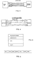
- Figures 1A, 1B present various embodiments of the invention.
- a radio telephone is connected via a serial bus in accordance with the invention to an external adaptor provided as a separate means and adapting the data passing via the DCE interface from a Personal Computer (PC) to the serial bus and to the protocol used by the bearer service.
- the adaptor is a card connected to the PC, e.g. to a free card location, whereby the adaptor is directly connected to the internal data bus of the PC.
- a facsimile device has been connected to a phone with the aid of an adaption card and a serial bus cable. Now, the adaptation card replaces a conventional analog modem.
- the interface adaptor has been connected via a serial bus to the mobile phone. All signalling, control and traffic data pass via the bus. The messages are guided into the correct block within the radio telephone according to the address associated with the message.
- the signalling protocols are processed by a general-purpose microprocessor and the channel coding/decoding is carried out by a signal processor DSP.
- Block 1 in the adaptor comprises a standard interface through which connection to a fax device or a PC is made.
- the interface of the interface block 1 is RS232 interface, whereby the adaptor can be connected to the asynchronous COM port of a PC, or it can be an interface conforming to a PC bus, whereby the adaptor is directly connected to the internal data bus of the PC.
- Block 2 of the adaptor is an automatic paging module which interprets the AT or V.25bis commands transmitted thereto by a PC, i.e. the commands of the modem.
- the data for facsimile transmission is conducted from the interface block 1 to a facsimile adaptor and bearer service module 3 that converts the outgoing data into data conforming to the protocol required by the bearer service used for that facility.
- Data in accordance with the desired protocol is conducted via the bus interface 4 to a fast serial bus.
- Data travelling via the serial bus arrives at the bus interface block 4 located in the radio telephone, said block guiding the data in accordance with the address included therein either to block 6 for performing signalling and control operations, (in practice the microprocessor of the radio telephone) or to the channel coder of the phone which is a signal processor DSP.
- the data is now in such form in which it can be conducted directly to the I/O gate so that no conversions need be made.
- the channel coder in block 5 codes both the control data from block 6 and the traffic data from an external bus, such as a facsimile message, whereby the coded information is transmitted via the radio unit 7 to the radio path.
- the data received from the radio path is decoded in decoder 5 and conducted as decoded control data or traffic data as such to the bus interface block which adapts the data for the external bus.
- the functions are performed in reverse order compared with the above-described description concerning the data transmitted by the terminal.
- the physical channel between the adaptor and the phone is an active channel, presented schematically in Figure 3.
- an active channel By using an active channel, the problems can be solved which would otherwise be produced when the adaptor or the phone is switched off or when power is connected to either of the means.
- Buffers are inserted in the connector of the cable facing the phone.
- a line is needed to supply the operating voltage VCC from the adaptor to the buffers, and a connector in the adaptor where through the operating voltage is supplied to the cable.
- the operating voltage VCC of the active buffering of the cable is provided by the adaptor and all signals towards the adaptor have been buffered.
- the active buffer becomes passive, as a result whereof no electrical connection prevails between the phone and the adaptor.
- the buffering reduces the power consumption of the radio unit when the bus is used normally. This is very important particularly when the phone is a battery operated phone, the aim being then as low a power consumption as possible.
- the active cable also reduces the detrimental phenomena caused by a long cable when the buffering is positioned as close to the apparatus to be protected as possible, in this case a phone.
- the buffering prevents the external interferences particularly when the cable is not connected to the data terminal and the free end of the cable lies in the vicinity of the source of interference.
- the buffering reduces interferences also when the phone makes attempts to transmit data when the interface adaptor is passive or the cable has been switched off at the other end. This is because a buffer in passive state will not let any signals through.
- the active cable also makes feasible the use of various operating voltages in the phone and in the interface adaptor because the conversion of the voltage levels can be performed in the cable.
- One element of the present embodiment is an external serial bus connecting the adaptor and the phone, said bus being physically implemented using the active cable described above.
- the bus is used as described briefly above, to transmit signalling, control information and traffic channel information.
- the protocol of the bus is a two-level protocol, whereby an errorless transmission of a control and signalling message is assured, but as to the information transmitted on the traffic channel, error detection is thought to be enough without any correction thereof.
- the physical bus connection interface in the phone, Figure 2 comprises five pins: (1) a pin for the data to be transmitted, (2) a pin for the data to be received, (3) a pin for transmitting clock pulses from the radio unit to the bus, (4) a pin for transmitting the synchronization pulses provided by the radio unit to the bus (each 8-bit byte passing via the bus is preceded by a synchronizing pulse), and (5), a grounding pin.
- the signals passing through the pins are at CMOS level and the bus has been buffered.
- the data rate is in the range of 50 to 150 kbit/s, whereby the maximum delay of a traffic channel frame is about 5 ms.
- one possibility to implement the physical layer of the synchronous data bus is to utilize the Serial Input/Output (SIO) interface of the DSP16 processor family, produced by AT&T.
- the signal processor of the DSP16 family in the phone performs channel coding and decoding.
- the signalling protocols are processed by MC68302 by Motorola in the adaptor (block 3, Figure 2), one of the serial communications controllers of which can be changed to operate transparently in the Pulse Code Modulation (PCM) highway mode operating almost entirely in the same way as the SIO interface of DSP.
- PCM Pulse Code Modulation
- FIG. 4 presents a physical connection between MC68302 microprocessor and DSP16 signal processor.
- the block on the left illustrates the signal processor of the phone which in the present example is Motorola DSP1610 but which could also be another suitable one.
- the block on the right illustrates a processor in a data adaptor, performing the adaption of the data to be transmitted to the protocol according to the service used, and respectively, conversion of the data according to the protocol of the received data into a form readable by the data terminal.
- the block generating the clock and synchronizing signals Clock Generation is located in the phone and that the signals are transmitted in conductors of their own via an external serial bus in accordance with the invention to a data adaptor at the other end of the bus.
- the labels of the signal connections in the signal processor are as follows:
- the labels of the interfaces of the microprocessor in the data adaptor are as follows:
- the synchronization of the LISYO and ICK inputs and, respectively, the clock signals are inverted in inverters.
- the synchronization and the clock signals are generated in the phone so that the descending edge of the synchronization signal is in the middle of the clock pulse when the pulse is up and the ascending edge of the synchronizing signal is in the middle of the clock pulse when the pulse is up or down.
- serial bus The physical implementation of a serial bus is presented in the foregoing with an active cable as well as the generation of the clock and synchronization signals.
- the data transfer protocol used in the bus is described below, referring to Figs. 5 and 6.
- Figure 5 presents a format of a message.
- the message is started with a target address, being a receiving block, a physical apparatus or a program task or a layer included therein.
- a device connected to the phone via the serial cable to communicate directly with both the channel coder/decoder and the signalling and control block of the phone, and additionally with any block having an address of its own.
- the address must, of course, deviate from the synchronization byte.
- a notice on the length of the data message is given, followed by the data message itself.
- the format thereof can be any one compatible with the data service used and supported by a program layer corresponding to the service.
- the message is transferred transparently via the bus. At the end of the message there are the parity bits.
- Figure 6 shows a part of the data flow passing in the bus, comprising messages according to Figure 5 and synchronization bytes therebetween. Since the bus is synchronous, particular synchronization bytes must be added in the data flow when there is no data to be transmitted. The receiver is recognizing them without paying any attention thereto. As mentioned above, the synchronization byte must deviate from any address used so that the receiver is capable of making difference between the synchronization byte and the start of the message. The data message following after the address field is received transparently, i.e. no correlation with the synchronization byte is looked for before reception of the entire message.
- the messages as those in Figure 5 can be signalling and control messages.
- the data included therein is related to the paging control, short message service and various internal operation procedures in the phone.
- the errorless nature of the transmission of signalling and control messages is assured in such a way that when transmitting a message, the acknowledgement timer is started and that the messages have an ordinal number so that the receiving end detects a message transmitted twice. If the parity check of a received message verifies that the message is errorless, an acknowledgement is sent with the same ordinal number as in the message. If instead, the checking shows that the message is erroneous, it is rejected and no acknowledgement is sent.
- the transmitting party transmits the message again, with the assumption that the maximum amount set for the repetition transmissions has not been exceeded. If exceeded, the data transmission is given up and the bus is assumed to be switched off from the phone.
- the messages according to Figure 5 may be also traffic channel messages. These are true information messages introduced to the channel coder to be transmitted further by the radio, or those received by the radio and decoded in the channel decoder. Differing from the control and signalling messages, the traffic channel messages are transmitted onwards even though the parity check shows that the message is erroneous. Depending on the service adopted, the receiver can either use or not use the erroneous information.
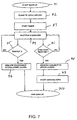
- FIG. 7 is a flow chart from the beginning of the activation of the bus, block 71.
- the clock signals of the bus are generated in the phone.
- the bus is, after switching on the operating voltage, in wake up state and there is no clock signal in the bus.
- the interface adaptor can request the phone to activate the bus by shifting the line of the data to be transmitted into the state 'low'. Said line is line L1TXD in the block on the right side in Figure 4.
- the timer limiting the permitted time for synchronization is also started, block 73.
- the state 'low' of the line causes in the processor controlling the state of the bus in the phone an interruption, whereafter it starts the transmission of clock pulses to the bus and the synchronization process starts.
- the interface adaptor and the phone transmit merely synchronization bytes to the bus.
- the adaptor expects the arrival thereof in block 74. If none of them arrives within the time set for the timer, the failure is indicated in switching to the upper layers in block 75, and more attempts are given up.
- After receiving a byte in block 76 the synchronization is completed successfully and the connection to the upper layers of the protocol is confirmed, block 78. Then, sync sending is started, block 79, and wake up is ended, block 710.
- the phone has also been enabled to activate a data bus when data addressed to a data terminal connected thereto is arriving. Now, the phone connects the clock signal to the bus.
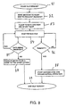
- the interface adaptor is capable of receiving data at any time, so that the process continues as shown in Figure 7.
- the procedure starts from block 81, start idle request.
- the interface adaptor may send a request for an entry to idle mode by transmitting a specific control message of its own to the phone (block 82) which the phone can accept (blocks 83, 84, 85, 87, 89) or refuse to accept (blocks 83, 86, 88,89). If the phone accepts the request, it will no longer transmit clock pulses to the bus.
- the adaptor waits for the decision of the phone for a given time (block 86), in the course of which it shifts the data transmission line into the state 'high' not to make the activation request of the bus, which is the state 'low' of the bus.
- the bus can be disconnected entirely from the phone when the cable is disconnected or it is damaged. In other words, from the point of view of the protocol, an error situation is in question. Disconnection of the bus is accomplished when there are neither clock pulses nor synchronization bytes, or when, within a given time, no messages have been observed, or when there is no confirmation of received signalling or control messages after retransmissions in the course of the time preset.
- the adaptor connects the data transmission line thereof into the state 'low'. It leads to a wake up disconnection of the bus in the processor of the phone when the cable is connected again.
- the phone disconnects the erection of the bus and a potential call is eliminated.
- the traffic can start as described in conjunction with Figure 7.
- bus and the adaptor may, while remaining within the protective scope of the accompanying claims, be implemented in a great number of different ways.
- a personal computer or a facsimile device can easily be connected to a digital mobile phone having no features supporting the data services of the network.
Landscapes
- Engineering & Computer Science (AREA)
- Computer Networks & Wireless Communication (AREA)
- Signal Processing (AREA)
- Mobile Radio Communication Systems (AREA)
- Communication Control (AREA)
Claims (15)
- Adapter zum Verbinden eines digitalen Funktelefons eines zellulären Netzwerks und eines Datenendgerätes mit
einem Umsetzer (2, 3) zum Umsetzen von Signalen, die einem ersten Protokoll entsprechen, in digitale Signale, die einem zweiten Protokoll entsprechen, das für das digitale Funktelefon geeignet ist,
einem ersten Schnittstellenblock (1) zum trennbaren Verbinden des Umsetzers mit dem einen der Geräte (digitales Funktelefon bzw. Datenendgerät) und
einem zweiten Schnittstellenblock (4) zum trennbaren Verbinden des Umsetzers mit dem anderen der Geräte (digitales Funktelefon bzw. Datenendgerät), dadurch gekennzeichnet, dass der Umsetzer (2, 3) so angeordnet ist, dass er das Umsetzen vornimmt, während das digitale Funktelefon und das Datenendgerät in einem Datenanruf über den Adapter kommunizieren, um Zugriff auf Datendienste des zellulären Netzes zu erlauben. - Adapter nach Anspruch 1,wobei es sich bei den Signalen, die dem ersten Protokoll entsprechen, um Signale handelt, die von einem seriellen Datenbus empfangen werden.
- Adapter nach Anspruch 1 oder 2,wobei es sich bei den Signalen, die dem zweiten Protokoll entsprechen, um Signale handelt, die für einen seriellen Datenbus des Datenendgerätes angepasst sind.
- Adapter nach einem der vorhergehenden Ansprüche, wobei der erste Schnittstellenblock (1) dafür angepasst ist, vom digitalen Funktelefon sowohl Steuerdaten als auch Verkehrsdaten zu empfangen.
- Adapter nach einem der vorhergehenden Ansprüche, wobei der erste Schnittstellenblock (1) einen synchronen Datenbus umfasst, der für das Verbinden mit dem digitalen Funktelefon angepasst ist.
- Adapter nach Anspruch 5, wobei der erste Schnittstellenblock (1) angepasst ist, um den Umsetzer mit einer Zentraleinheit und einem Kanalcodierer des digitalen Funktelefons über einen dritten Schnittstellenblock (6) im digitalen Funktelefon zu verbinden.
- Adapter nach einem der Ansprüche 5 oder 6, wobei Mittel zum Unterbrechen der Datenübertragung entlang des synchronen Datenbusses bereitgestellt sind.
- Adapter nach Anspruch 6, wobei die Mittel zum Unterbrechen auf den Umsetzer ansprechen.
- Adapter nach einem der vorhergehenden Ansprüche, wobei das zweite Protokoll für einen Datenanruf angepasst ist.
- Adapter nach Anspruch 9, wobei es sich bei dem Datenanruf um einen durchschaltevermittelten oder einen paketvermittelten Datenanruf handelt.
- Adapter nach einem der vorhergehenden Ansprüche, wobei es sich bei den ersten und zweiten Schnittstellenblöcken um erste und zweite Verbindungskomponenten handelt.
- Verfahren zur Nutzung von Datendiensten, die von einem zellulären Netzwerk bereitgestellt werden, beinhaltend das Verbinden eines digitalen Funktelefons und eines Datenendgerätes mithilfe eines Adapters, der einen Umsetzer zum Umsetzen von Signalen, die einem ersten Protokoll entsprechen, in Signale, die einem zweiten Protokoll digitaler Signale entsprechen, das für das digitale Funktelefon geeignet ist, und umgekehrt, einen ersten Schnittstellenblock zum trennbaren Verbinden des Umsetzers mit dem digitalen Funktelefon und einen zweiten Schnittstellenblocks zum trennbaren Verbinden des Umsetzers mit dem Datenendgerät aufweist, das Senden von Signalen von einem der Geräte (digitales Funktelefon bzw. Datenendgerät) in einem der ersten und zweiten Protokolle,
das Umsetzen der Signale, die von einem der der ersten und zweiten Protokolle übertragen wurden, in das andere der ersten und zweiten Protokolle und
das Senden bzw. Empfangen von Signalen zur Übertragung an das bzw. von dem Datenendgerät über das digitale Funktelefon und ein zelluläres Netzwerk, dadurch gekennzeichnet, dass das Umsetzen erfolgt, während das digitale Funktelefon und das Datenendgerät in einem Datenanruf über den Adapter kommunizieren, um Zugriff auf Datendienste des zellulären Netzes zu erlauben. - Verfahren nach Anspruch 12, wobei der erste Schnittstellenblock auf Signale vom digitalen Funktelefon anspricht, um die Datenübertragung zu unterbrechen.
- Verfahren nach Anspruch 12 oder 13, wobei der erste Schnittstellenblock auf Signale vom Datenendgerät anspricht, um die Datenübertragung zu unterbrechen.
- Verfahren nach Anspruch 12 bis 14, wobei es sich bei den ersten und zweiten Schnittstellenblöcken um erste und zweite Verbindungskomponenten handelt.
Applications Claiming Priority (2)
| Application Number | Priority Date | Filing Date | Title |
|---|---|---|---|
| FI935347 | 1993-11-30 | ||
| FI935347A FI110833B (fi) | 1993-11-30 | 1993-11-30 | Menetelmä ja laitteisto datan siirtämiseksi digitaalisen matkapuhelimen ja siihen liitettävän ulkoisen datapäätelaitteen välillä |
Publications (3)
| Publication Number | Publication Date |
|---|---|
| EP0655873A2 EP0655873A2 (de) | 1995-05-31 |
| EP0655873A3 EP0655873A3 (de) | 1998-07-22 |
| EP0655873B1 true EP0655873B1 (de) | 2005-02-09 |
Family
ID=8539052
Family Applications (1)
| Application Number | Title | Priority Date | Filing Date |
|---|---|---|---|
| EP94308829A Expired - Lifetime EP0655873B1 (de) | 1993-11-30 | 1994-11-30 | Adapter für Datenübertragung von und zu einem Funktelefon |
Country Status (5)
| Country | Link |
|---|---|
| US (1) | US5903849A (de) |
| EP (1) | EP0655873B1 (de) |
| DE (2) | DE69434266T2 (de) |
| ES (1) | ES2096537T3 (de) |
| FI (1) | FI110833B (de) |
Families Citing this family (38)
| Publication number | Priority date | Publication date | Assignee | Title |
|---|---|---|---|---|
| FI98028C (fi) * | 1995-05-03 | 1997-03-25 | Nokia Mobile Phones Ltd | Datasovitin |
| GB2301987B (en) * | 1995-06-05 | 2000-01-12 | Nokia Mobile Phones Ltd | Radio telephone text transmission system |
| SE515582C2 (sv) * | 1995-07-07 | 2001-09-03 | Datasoft Systems Ab | Anordning för trådlös kommunikation |
| FI111309B (fi) * | 1996-01-03 | 2003-06-30 | Nokia Corp | Tietoliikenneverkkoon radioteitse liitettävä päätelaite |
| FR2744315B1 (fr) * | 1996-01-26 | 2000-08-04 | Sagem | Terminal voix-donnees pour reseau telephonique radio |
| US7107072B1 (en) * | 1996-02-20 | 2006-09-12 | Texas Instruments Incorporated | Interface module for a portable telephone that facilitates direct portable telephone/portable computer coupling |
| AU2287797A (en) * | 1996-03-13 | 1997-10-01 | Telefonaktiebolaget Lm Ericsson (Publ) | A communication method and an adapter between a wireless telephone terminal and a data source |
| BE1010266A4 (nl) * | 1996-04-15 | 1998-04-07 | Option International | Aanpassingseenheid voor datatransmissie tussen een mobiele telefoon en een gegevensterminal. |
| GB9608717D0 (en) * | 1996-04-26 | 1996-07-03 | Maxon Systems Inc London Limit | Terminal concentrator |
| EP0812095A3 (de) * | 1996-06-07 | 2000-01-05 | Ntt Mobile Communications Network Inc. | Stromversorgung für Kommunikationsendgerät durch die Batterie eines Mobiltelefons |
| DE19636617C2 (de) * | 1996-09-10 | 2002-08-01 | Deutsche Telekom Ag | Schnurloser Telefonapparat |
| FI105859B (fi) * | 1997-02-21 | 2000-10-13 | Nokia Mobile Phones Ltd | Menetelmä digitaalisen signaalinkäsittely-yksikön audioparametrien asettamiseksi elektroniikkalaitteessa ja elektroniikkalaite |
| FR2760922B1 (fr) * | 1997-03-12 | 1999-05-07 | Sagem | Procede d'echange de donnees, avec adaptation, entre un reseau radio de communication et des moyens de traitement de donnees |
| FR2760920B1 (fr) * | 1997-03-12 | 2000-08-04 | Sagem | Procede de transmission de donnees entre des moyens de traitement de donnees et un reseau de radiocommunication et module et terminal mobile pour la mise en oeuvre du procede |
| US6012105A (en) * | 1997-05-01 | 2000-01-04 | Telefonaktiebolaget L M Ericsson | System for interfacing with an external accessory in one of two interface modes based on whether communication can be established with external accessory or not |
| FI973415A7 (fi) * | 1997-08-20 | 1999-02-21 | Nokia Corp | Kannettavat elektroniset laitteet |
| US6934551B1 (en) * | 1997-10-09 | 2005-08-23 | Mci Communications Corporation | Method for wireless data transmission for adaptive multiple protocols |
| JP3230478B2 (ja) * | 1998-01-08 | 2001-11-19 | 日本電気株式会社 | パケット通信カード |
| JP3200585B2 (ja) * | 1998-02-10 | 2001-08-20 | 富士通株式会社 | 携帯電話機及び情報通信用アダプタ |
| FI110456B (fi) | 1998-03-09 | 2003-01-31 | Nokia Corp | Järjestelmä ympäristömittausten suorittamiseksi ja mittaustietojen välittämiseksi |
| JP3663053B2 (ja) * | 1998-06-11 | 2005-06-22 | シャープ株式会社 | 携帯電話機 |
| FI117523B (fi) * | 1998-10-07 | 2006-11-15 | Nokia Corp | Menetelmä tehonkulutuksen säätämiseksi |
| FR2791208B1 (fr) * | 1999-03-16 | 2001-04-20 | Sagem | Procede de transmission de telecopies entre deux telecopieurs relies a un reseau de transmission de donnees |
| FR2795584B1 (fr) * | 1999-06-23 | 2001-08-10 | Sagem | Appareil autonome et procede de gestion par un tel appareil d'un transmetteur |
| DE19937710A1 (de) | 1999-08-10 | 2001-02-15 | Siemens Ag | Verfahren zur Übergabe einer bestehenden logischen Datenverbindung |
| AU7346800A (en) * | 1999-09-02 | 2001-03-26 | Automated Business Companies | Communication and proximity authorization systems |
| JP3789725B2 (ja) * | 2000-05-26 | 2006-06-28 | 富士通株式会社 | 通信デバイス |
| JP2002094689A (ja) * | 2000-06-07 | 2002-03-29 | Sony Computer Entertainment Inc | プログラム実行システム、プログラム実行装置、中継装置、および記録媒体 |
| US7376769B1 (en) * | 2000-09-14 | 2008-05-20 | Intel Corporation | Wireless computing device having an application and wireless subsystem and method therefore |
| US6718182B1 (en) * | 2000-09-18 | 2004-04-06 | Compal Electronics, Inc. | Modularized functionality enhancement for a cellular telephone |
| SE522704C2 (sv) * | 2000-10-09 | 2004-03-02 | Ericsson Telefon Ab L M | Överföring av ljuddata och icke ljuddata mellan en bärbar ch kommunikationsapparat och en extern terminal |
| DE10153446A1 (de) * | 2001-01-04 | 2003-05-22 | Zwick Harry | Steuerungs- und/oder Überwachungseinrichtung mit einem Schaltgerät |
| JP2002359660A (ja) * | 2001-03-28 | 2002-12-13 | Sony Computer Entertainment Inc | データ通信装置及び方法、データ通信システム、データ通信プログラムを記録した記録媒体、データ通信プログラム |
| US7664527B2 (en) * | 2006-08-04 | 2010-02-16 | At&T Mobility Ii Llc | Network identity and timezone (NITZ) functionality for non-3GPP devices |
| FI20065765A0 (fi) * | 2006-11-30 | 2006-11-30 | Nokia Corp | Pakettiradiotiedonsiirtolaite |
| US8086781B2 (en) * | 2007-06-22 | 2011-12-27 | Apple Inc. | Serial pass-through device |
| US8078787B2 (en) | 2007-06-22 | 2011-12-13 | Apple Inc. | Communication between a host device and an accessory via an intermediate device |
| JP6415537B2 (ja) * | 2014-03-11 | 2018-10-31 | セイコーインスツル株式会社 | 通信システム |
Family Cites Families (16)
| Publication number | Priority date | Publication date | Assignee | Title |
|---|---|---|---|---|
| US4369516A (en) * | 1980-09-15 | 1983-01-18 | Motorola, Inc. | Self-clocking data transmission system |
| US4390963A (en) * | 1980-09-15 | 1983-06-28 | Motorola, Inc. | Interface adapter architecture |
| US4486624A (en) * | 1980-09-15 | 1984-12-04 | Motorola, Inc. | Microprocessor controlled radiotelephone transceiver |
| US4697281A (en) * | 1986-03-14 | 1987-09-29 | Spectrum Cellular Communications Corporation, Inc. | Cellular telephone data communication system and method |
| US4972457A (en) * | 1989-01-19 | 1990-11-20 | Spectrum Information Technologies, Inc. | Portable hybrid communication system and methods |
| FI82573C (fi) * | 1989-05-17 | 1991-03-11 | Nokia Mobira Oy | Kretsanordning vid en mobiltelefon foer ett allmaeneuropeiskt digitalt mobiltelefonsystem. |
| WO1991007044A1 (en) * | 1989-10-31 | 1991-05-16 | Intelligence Technology Corporation | Data and voice transmission over a cellular telephone system |
| US5127041A (en) * | 1990-06-01 | 1992-06-30 | Spectrum Information Technologies, Inc. | System and method for interfacing computers to diverse telephone networks |
| US5257397A (en) * | 1990-08-13 | 1993-10-26 | At&T Bell Laboratories | Mobile data telephone |
| JP3058923B2 (ja) * | 1991-01-11 | 2000-07-04 | 株式会社東芝 | 無線電話装置アダプタ |
| US5237570A (en) * | 1991-07-18 | 1993-08-17 | Motorola, Inc. | Prioritized data transfer method and apparatus for a radiotelephone peripheral |
| FI89223C (fi) * | 1991-10-03 | 1993-08-25 | Nokia Mobile Phones Ltd | Digitalt audiointerface i gsm-anordning |
| FI98183C (fi) * | 1992-02-14 | 1997-04-25 | Nokia Mobile Phones Ltd | Järjestely data-adapterin kytkemiseksi GSM-solukkopuhelimeen |
| US5249218A (en) * | 1992-04-06 | 1993-09-28 | Spectrum Information Technologies, Inc. | Programmable universal interface system |
| US5483576A (en) * | 1993-03-31 | 1996-01-09 | Data Race, Inc. | Method and apparatus for communicating data over a radio transceiver with a modem |
| US5649001A (en) * | 1995-03-24 | 1997-07-15 | U.S. Robotics Mobile Communications Corp. | Method and apparatus for adapting a communication interface device to multiple networks |
-
1993
- 1993-11-30 FI FI935347A patent/FI110833B/fi active
-
1994
- 1994-11-30 EP EP94308829A patent/EP0655873B1/de not_active Expired - Lifetime
- 1994-11-30 DE DE69434266T patent/DE69434266T2/de not_active Expired - Lifetime
- 1994-11-30 DE DE0655873T patent/DE655873T1/de active Pending
- 1994-11-30 ES ES94308829T patent/ES2096537T3/es not_active Expired - Lifetime
-
1997
- 1997-02-27 US US08/807,285 patent/US5903849A/en not_active Expired - Lifetime
Also Published As
| Publication number | Publication date |
|---|---|
| DE69434266D1 (de) | 2005-03-17 |
| US5903849A (en) | 1999-05-11 |
| FI935347A0 (fi) | 1993-11-30 |
| ES2096537T1 (es) | 1997-03-16 |
| FI935347L (fi) | 1995-05-31 |
| DE69434266T2 (de) | 2005-06-30 |
| EP0655873A2 (de) | 1995-05-31 |
| EP0655873A3 (de) | 1998-07-22 |
| ES2096537T3 (es) | 2005-07-16 |
| DE655873T1 (de) | 1997-05-15 |
| FI110833B (fi) | 2003-03-31 |
Similar Documents
| Publication | Publication Date | Title |
|---|---|---|
| EP0655873B1 (de) | Adapter für Datenübertragung von und zu einem Funktelefon | |
| RU2183907C2 (ru) | Система интерфейса сотовых телефонов для услуг передачи данных стандарта amps и множественного доступа с кодовым разделением каналов | |
| CA2005508C (en) | Multiplexed synchronous/asynchronous data bus | |
| CN1135007C (zh) | 用于话音和非话音通信的系统、方法和通信站 | |
| KR100187823B1 (ko) | Cdma 이동데이타통신 제어시스템 | |
| US6526288B1 (en) | System for connecting a data communication device over wireless terminals to a communication network | |
| KR920007409A (ko) | 종합 정보 통신망용 텔리폰 세트 | |
| US5835785A (en) | Multiplexed three line synchronous/full-duplex asychronous data bus and method therefor | |
| WO1992002993A1 (en) | Multiplexed synchronous/asynchronous data bus | |
| FI107101B (fi) | Tietokoneen liittäminen radiopuhelimeen | |
| JP3893621B2 (ja) | データ及び音声の伝送方法及び装置 | |
| US7154865B1 (en) | Application module interface for bidirectional signaling and bearer channels in a private branch exchange (PBX) environment | |
| US5490146A (en) | Digital mobile radio system interfacing an ISDN standard bus system | |
| KR100710268B1 (ko) | 이종 마이크로 프로세서 모듈 사이의 음성 호 송·수신방법 | |
| KR100378823B1 (ko) | 사설교환기의 무선통화 회선카드간 데이터 전송방법 | |
| KR20000030918A (ko) | 셀룰라 무선통신 단말기의 인터페이스 장치 | |
| KR19980065539A (ko) | 유선전화망을 통해 통화가능한 휴대용 통신기기 및 그 통화수행 방법 | |
| FI109074B (fi) | Tilaajamultipleksointilaite | |
| JP3947312B2 (ja) | データ通信処理装置 | |
| JP3093666B2 (ja) | コンピュータ通信方式 | |
| KR100404565B1 (ko) | 브이오아이피 게이트웨이 시스템에서의 아이피 망 접속 구조 | |
| JP2006279949A (ja) | ネットワーク通信設備及びこれを使用したネットワーク通信システム | |
| JP3033942B2 (ja) | データ通信システムで使用されるデータ制御装置 | |
| KR20000043349A (ko) | 이동데이터 통신 제어시스템 | |
| KR20030075964A (ko) | 개인 휴대 정보 단말기에서의 음성 통화 장치 및 그 방법 |
Legal Events
| Date | Code | Title | Description |
|---|---|---|---|
| PUAI | Public reference made under article 153(3) epc to a published international application that has entered the european phase |
Free format text: ORIGINAL CODE: 0009012 |
|
| AK | Designated contracting states |
Kind code of ref document: A2 Designated state(s): DE ES FR GB NL SE |
|
| EL | Fr: translation of claims filed | ||
| REG | Reference to a national code |
Ref country code: ES Ref legal event code: BA2A Ref document number: 2096537 Country of ref document: ES Kind code of ref document: T1 |
|
| TCNL | Nl: translation of patent claims filed | ||
| EL | Fr: translation of claims filed |
Free format text: CORRECTIONS |
|
| DET | De: translation of patent claims | ||
| PUAL | Search report despatched |
Free format text: ORIGINAL CODE: 0009013 |
|
| AK | Designated contracting states |
Kind code of ref document: A3 Designated state(s): DE ES FR GB NL SE |
|
| 17P | Request for examination filed |
Effective date: 19990122 |
|
| 17Q | First examination report despatched |
Effective date: 20001114 |
|
| RAP1 | Party data changed (applicant data changed or rights of an application transferred) |
Owner name: NOKIA CORPORATION |
|
| GRAP | Despatch of communication of intention to grant a patent |
Free format text: ORIGINAL CODE: EPIDOSNIGR1 |
|
| GRAS | Grant fee paid |
Free format text: ORIGINAL CODE: EPIDOSNIGR3 |
|
| GRAA | (expected) grant |
Free format text: ORIGINAL CODE: 0009210 |
|
| AK | Designated contracting states |
Kind code of ref document: B1 Designated state(s): DE ES FR GB NL SE |
|
| REG | Reference to a national code |
Ref country code: GB Ref legal event code: FG4D |
|
| REF | Corresponds to: |
Ref document number: 69434266 Country of ref document: DE Date of ref document: 20050317 Kind code of ref document: P |
|
| REG | Reference to a national code |
Ref country code: SE Ref legal event code: TRGR |
|
| REG | Reference to a national code |
Ref country code: ES Ref legal event code: FG2A Ref document number: 2096537 Country of ref document: ES Kind code of ref document: T3 |
|
| PLBE | No opposition filed within time limit |
Free format text: ORIGINAL CODE: 0009261 |
|
| STAA | Information on the status of an ep patent application or granted ep patent |
Free format text: STATUS: NO OPPOSITION FILED WITHIN TIME LIMIT |
|
| ET | Fr: translation filed | ||
| 26N | No opposition filed |
Effective date: 20051110 |
|
| PGFP | Annual fee paid to national office [announced via postgrant information from national office to epo] |
Ref country code: NL Payment date: 20081103 Year of fee payment: 15 |
|
| PGFP | Annual fee paid to national office [announced via postgrant information from national office to epo] |
Ref country code: ES Payment date: 20081216 Year of fee payment: 15 |
|
| PGFP | Annual fee paid to national office [announced via postgrant information from national office to epo] |
Ref country code: SE Payment date: 20081107 Year of fee payment: 15 |
|
| PGFP | Annual fee paid to national office [announced via postgrant information from national office to epo] |
Ref country code: GB Payment date: 20081126 Year of fee payment: 15 |
|
| PGFP | Annual fee paid to national office [announced via postgrant information from national office to epo] |
Ref country code: DE Payment date: 20091126 Year of fee payment: 16 |
|
| PGFP | Annual fee paid to national office [announced via postgrant information from national office to epo] |
Ref country code: FR Payment date: 20091123 Year of fee payment: 16 |
|
| REG | Reference to a national code |
Ref country code: NL Ref legal event code: V1 Effective date: 20100601 |
|
| EUG | Se: european patent has lapsed | ||
| GBPC | Gb: european patent ceased through non-payment of renewal fee |
Effective date: 20091130 |
|
| PG25 | Lapsed in a contracting state [announced via postgrant information from national office to epo] |
Ref country code: NL Free format text: LAPSE BECAUSE OF NON-PAYMENT OF DUE FEES Effective date: 20100601 |
|
| PG25 | Lapsed in a contracting state [announced via postgrant information from national office to epo] |
Ref country code: GB Free format text: LAPSE BECAUSE OF NON-PAYMENT OF DUE FEES Effective date: 20091130 |
|
| REG | Reference to a national code |
Ref country code: ES Ref legal event code: FD2A Effective date: 20110307 |
|
| PG25 | Lapsed in a contracting state [announced via postgrant information from national office to epo] |
Ref country code: SE Free format text: LAPSE BECAUSE OF NON-PAYMENT OF DUE FEES Effective date: 20091201 |
|
| PG25 | Lapsed in a contracting state [announced via postgrant information from national office to epo] |
Ref country code: ES Free format text: LAPSE BECAUSE OF NON-PAYMENT OF DUE FEES Effective date: 20110304 |
|
| REG | Reference to a national code |
Ref country code: DE Ref legal event code: R119 Ref document number: 69434266 Country of ref document: DE Effective date: 20110601 Ref country code: DE Ref legal event code: R119 Ref document number: 69434266 Country of ref document: DE Effective date: 20110531 |
|
| REG | Reference to a national code |
Ref country code: FR Ref legal event code: ST Effective date: 20110801 |
|
| PG25 | Lapsed in a contracting state [announced via postgrant information from national office to epo] |
Ref country code: ES Free format text: LAPSE BECAUSE OF NON-PAYMENT OF DUE FEES Effective date: 20091201 Ref country code: DE Free format text: LAPSE BECAUSE OF NON-PAYMENT OF DUE FEES Effective date: 20110531 |
|
| PG25 | Lapsed in a contracting state [announced via postgrant information from national office to epo] |
Ref country code: FR Free format text: LAPSE BECAUSE OF NON-PAYMENT OF DUE FEES Effective date: 20101130 |