EP0656267A1 - Wälzlager mit fluiddichter Verbindungsvorrichtung - Google Patents
Wälzlager mit fluiddichter Verbindungsvorrichtung Download PDFInfo
- Publication number
- EP0656267A1 EP0656267A1 EP94402735A EP94402735A EP0656267A1 EP 0656267 A1 EP0656267 A1 EP 0656267A1 EP 94402735 A EP94402735 A EP 94402735A EP 94402735 A EP94402735 A EP 94402735A EP 0656267 A1 EP0656267 A1 EP 0656267A1
- Authority
- EP
- European Patent Office
- Prior art keywords
- bearing
- rotating
- intermediate chamber
- fluid
- friction contact
- Prior art date
- Legal status (The legal status is an assumption and is not a legal conclusion. Google has not performed a legal analysis and makes no representation as to the accuracy of the status listed.)
- Granted
Links
- 239000012530 fluid Substances 0.000 title claims abstract description 33
- 238000007789 sealing Methods 0.000 claims abstract description 62
- 238000005096 rolling process Methods 0.000 claims abstract description 5
- 239000002184 metal Substances 0.000 claims description 6
- 239000004519 grease Substances 0.000 claims description 3
- 230000001050 lubricating effect Effects 0.000 claims description 3
- 238000003754 machining Methods 0.000 claims description 2
- 239000004809 Teflon Substances 0.000 description 3
- 229920006362 Teflon® Polymers 0.000 description 3
- 229920001971 elastomer Polymers 0.000 description 3
- 229910000831 Steel Inorganic materials 0.000 description 2
- 239000011248 coating agent Substances 0.000 description 2
- 238000000576 coating method Methods 0.000 description 2
- 239000000806 elastomer Substances 0.000 description 2
- 239000000314 lubricant Substances 0.000 description 2
- 239000000463 material Substances 0.000 description 2
- 238000000034 method Methods 0.000 description 2
- 239000010959 steel Substances 0.000 description 2
- 210000002105 tongue Anatomy 0.000 description 2
- 238000004891 communication Methods 0.000 description 1
- 230000001276 controlling effect Effects 0.000 description 1
- 230000007423 decrease Effects 0.000 description 1
- 230000010354 integration Effects 0.000 description 1
- 230000000149 penetrating effect Effects 0.000 description 1
- 230000001105 regulatory effect Effects 0.000 description 1
- 230000003014 reinforcing effect Effects 0.000 description 1
Images

Classifications
-
- F—MECHANICAL ENGINEERING; LIGHTING; HEATING; WEAPONS; BLASTING
- F16—ENGINEERING ELEMENTS AND UNITS; GENERAL MEASURES FOR PRODUCING AND MAINTAINING EFFECTIVE FUNCTIONING OF MACHINES OR INSTALLATIONS; THERMAL INSULATION IN GENERAL
- F16C—SHAFTS; FLEXIBLE SHAFTS; ELEMENTS OR CRANKSHAFT MECHANISMS; ROTARY BODIES OTHER THAN GEARING ELEMENTS; BEARINGS
- F16C33/00—Parts of bearings; Special methods for making bearings or parts thereof
- F16C33/72—Sealings
- F16C33/76—Sealings of ball or roller bearings
-
- B—PERFORMING OPERATIONS; TRANSPORTING
- B60—VEHICLES IN GENERAL
- B60C—VEHICLE TYRES; TYRE INFLATION; TYRE CHANGING; CONNECTING VALVES TO INFLATABLE ELASTIC BODIES IN GENERAL; DEVICES OR ARRANGEMENTS RELATED TO TYRES
- B60C23/00—Devices for measuring, signalling, controlling, or distributing tyre pressure or temperature, specially adapted for mounting on vehicles; Arrangement of tyre inflating devices on vehicles, e.g. of pumps or of tanks; Tyre cooling arrangements
- B60C23/001—Devices for manually or automatically controlling or distributing tyre pressure whilst the vehicle is moving
- B60C23/003—Devices for manually or automatically controlling or distributing tyre pressure whilst the vehicle is moving comprising rotational joints between vehicle-mounted pressure sources and the tyres
- B60C23/00363—Details of sealings
-
- F—MECHANICAL ENGINEERING; LIGHTING; HEATING; WEAPONS; BLASTING
- F16—ENGINEERING ELEMENTS AND UNITS; GENERAL MEASURES FOR PRODUCING AND MAINTAINING EFFECTIVE FUNCTIONING OF MACHINES OR INSTALLATIONS; THERMAL INSULATION IN GENERAL
- F16C—SHAFTS; FLEXIBLE SHAFTS; ELEMENTS OR CRANKSHAFT MECHANISMS; ROTARY BODIES OTHER THAN GEARING ELEMENTS; BEARINGS
- F16C19/00—Bearings with rolling contact, for exclusively rotary movement
- F16C19/02—Bearings with rolling contact, for exclusively rotary movement with bearing balls essentially of the same size in one or more circular rows
- F16C19/14—Bearings with rolling contact, for exclusively rotary movement with bearing balls essentially of the same size in one or more circular rows for both radial and axial load
- F16C19/18—Bearings with rolling contact, for exclusively rotary movement with bearing balls essentially of the same size in one or more circular rows for both radial and axial load with two or more rows of balls
- F16C19/181—Bearings with rolling contact, for exclusively rotary movement with bearing balls essentially of the same size in one or more circular rows for both radial and axial load with two or more rows of balls with angular contact
- F16C19/183—Bearings with rolling contact, for exclusively rotary movement with bearing balls essentially of the same size in one or more circular rows for both radial and axial load with two or more rows of balls with angular contact with two rows at opposite angles
- F16C19/184—Bearings with rolling contact, for exclusively rotary movement with bearing balls essentially of the same size in one or more circular rows for both radial and axial load with two or more rows of balls with angular contact with two rows at opposite angles in O-arrangement
-
- F—MECHANICAL ENGINEERING; LIGHTING; HEATING; WEAPONS; BLASTING
- F16—ENGINEERING ELEMENTS AND UNITS; GENERAL MEASURES FOR PRODUCING AND MAINTAINING EFFECTIVE FUNCTIONING OF MACHINES OR INSTALLATIONS; THERMAL INSULATION IN GENERAL
- F16C—SHAFTS; FLEXIBLE SHAFTS; ELEMENTS OR CRANKSHAFT MECHANISMS; ROTARY BODIES OTHER THAN GEARING ELEMENTS; BEARINGS
- F16C41/00—Other accessories, e.g. devices integrated in the bearing not relating to the bearing function as such
- F16C41/005—Fluid passages not relating to lubrication or cooling
-
- F—MECHANICAL ENGINEERING; LIGHTING; HEATING; WEAPONS; BLASTING
- F16—ENGINEERING ELEMENTS AND UNITS; GENERAL MEASURES FOR PRODUCING AND MAINTAINING EFFECTIVE FUNCTIONING OF MACHINES OR INSTALLATIONS; THERMAL INSULATION IN GENERAL
- F16C—SHAFTS; FLEXIBLE SHAFTS; ELEMENTS OR CRANKSHAFT MECHANISMS; ROTARY BODIES OTHER THAN GEARING ELEMENTS; BEARINGS
- F16C2326/00—Articles relating to transporting
- F16C2326/01—Parts of vehicles in general
- F16C2326/02—Wheel hubs or castors
Definitions
- the present invention relates to the field of seals for the passage of a fluid between two parts, one of which is rotated relative to the other.
- the invention relates to a bearing fitted with a fluid passage which passes through the rotating and non-rotating rings of the bearing, as well as a sealing device for the passage of the fluid through the bearing.
- European patent application 0 362 921 discloses a bearing fitted with a sealing device mounted between two rows of balls and between the orifices arranged on the outer ring and the orifices arranged on the inner ring of the bearing. so as to ensure the passage of a fluid through the bearing.
- This bearing makes it possible to establish communication between two chambers containing a fluid under pressure.
- the sealing device ensures on the one hand the passage of the fluid through the bearing and on the other hand prevents the lubricant of the bearing such as the grease from penetrating the zones of passage of the fluid in the bearing.
- This sealing device however has a large axial size, which may be incompatible with certain applications.
- a common application of this technique is intended for controlling and regulating the pressure of the tires of a vehicle, the sealing device for fluid passage being mounted in the wheel bearings of the vehicle.
- Each seal has a metal frame on which is molded a sealing lip.
- the seals are secured to the fixed part of the hub by means of their metal frame, their sealing lips being in frictional contact with a cylindrical bearing arranged on the rotating part. of the hub.
- Each sealing lip is supported by an axial portion of the seal having a certain flexibility in the radial direction.
- the object of the present invention is to remedy the aforementioned drawbacks of existing techniques by proposing a bearing fitted with an effective sealing device and having a reduced axial size to allow its easy integration into the bearing.
- Another object of the invention is to provide a sealing device for the fluid passing through the bearing for which the contact pressure of the sealing lips with respect to a bearing surface varies in the same direction as the pressure of the fluid passing through the sealing device.
- the sealing device is arranged between a rotating ring and a non-rotating ring of a bearing in order to ensure the passage of a fluid between said rings which are each traversed by fluid passage channels.
- a sealed intermediate chamber of annular shape is thus formed between the rotating and non-rotating rings of the bearing and communicates with the fluid passage channels of said rings.
- the sealing device is fixedly mounted on one of the rings which can be rotating or non-rotating, the intermediate chamber extending towards the other ring by flexible walls, the end portion of which constitutes a sealing lip which is in rubbing contact with respect to a bearing surface of the other ring of the bearing.
- the friction contact surfaces of the other ring are surfaces of revolution inclined relative to the axis of rotation of the bearing.
- the flexible walls of the sealed intermediate chamber are substantially parallel to the contact contact surfaces of such that the contact pressure between the sealing lips and the bearing surfaces varies in the same direction as the pressure of the fluid in the intermediate chamber.
- the friction contact surfaces of the bearing have for straight line segments or curve segments.
- the inclination of said bearing surfaces relative to the axis of the bearing is preferably between 10 ° and 90 ° in order to reduce the axial extent of the flexible walls of the sealed intermediate chamber and of the sealing lips of the sealing device .
- the sealing lips of the sealing device may include in their friction zone a coating having better friction and sealing characteristics compared to the rest of the lips.
- the product known as Teflon is quite satisfactory in this regard.
- the flexible walls of the intermediate chamber also have two secondary external sealing lips for the lubricant contained in the bearing. The secondary sealing lips make it possible to protect the friction zones of the sealing lips against the fluid against the lubricating product of the bearing.
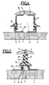
- the bearing illustrated in FIG. 1 comprises an outer ring 1, an inner ring 2 formed by two joined half-rings axially, and two rows of rolling balls 3 which are spaced circumferentially by cages 4.
- the outer ring 1 and the inner ring 2 can be rotated relative to each other.
- the outer ring 1 can be fixed or rotating.
- the bearing is protected from the outside environment by two annular lateral seals 5.
- two annular lateral seals 5 In a radial plane located between the two rows of balls 3 are several external radial channels 6 passing through the external ring 1 of the bearing, and several internal radial channels 7 passing through the inner ring 2 of the bearing.
- a sealing device 8 In the annular space formed by the outer 1 and inner 2 rings and the two rows of balls 3 is mounted a sealing device 8 allowing the passage of a fluid between the outer 6 and inner 7 channels of the bearing.
- the sealing device 8 is formed in this example from two separate annular seals 9 which are mounted opposite axially symmetrically with respect to the radial plane passing through the outer 6 and inner channels 7 of the bearing rings.
- Each seal 9 comprises a metal frame overmolded by a flexible material, such as an elastomer.
- the metal frame is formed by a sheet of steel folded so as to present an axial fitting part 10 on the outer ring 1 of the bearing and a radial reinforcing part for the flexible overmolding material which is extended into a flexible wall. 11, the free end of which constitutes a contact lip 12 rubbing against an annular surface 13 arranged on the inner ring 2 of the bearing.
- the two seals 9 thus mounted delimit an annular intermediate chamber 14 for the passage of the fluid, the intermediate chamber 14 communicating with the external 6 and internal channels 7 for the passage of fluid.
- the friction contact bearing surfaces 13 arranged in the inner ring 2 are symmetrical with respect to the radial plane passing through the outer 6 and inner channels 7.
- the bearing surfaces 13 are inclined relative to the axis XX 'of the bearing.
- the flexible walls 11 of the intermediate chamber 14 supporting the sealing lips 12 extend in a substantially parallel direction to the rubbing contact ranges 13. Any variation in fluid pressure on the internal faces of the flexible walls 11 therefore results in a variation in the same direction of the contact pressure of the sealing lips 12 on the bearing surfaces 13.
- the inclination of the bearing surfaces 13 of rubbing contact is of the order of 45 ° relative to the axis XX 'of the bearing.
- the surfaces are oriented convergently towards the internal channels 7 for the passage of fluid.
- the friction zones of the sealing lips 12 are provided with a Teflon coating 12a which has the mechanical characteristics superior to rubber. or elastomer constituting the rest of the sealing lips 12.
- Secondary sealing lips 15 can also be provided in order to protect the sealing lips 12 from the lubricating grease of the rolling balls 3.
- the secondary sealing lips 15 may consist of two annular external tongues of the flexible walls 11. These secondary tongues 15 extend obliquely and are in rubbing contact on cylindrical surfaces of the inner ring 2.
- Figure 2 shows an alternative embodiment with respect to Figure 1.
- the friction contact surfaces 13 of the inner ring 2 are perpendicular to the axis of the bearing.
- the flexible walls 11 of the intermediate chamber 14 then extend substantially radially.
- the sealing device 8 comprises an annular central body 16 having an external circular fixing flange 17 embedded in an annular groove 18 arranged in the vicinity of the external channels 6 of the ring outer 1.
- the central body 16 has two inner sealing lips 12 which define between them the annular intermediate chamber 14 communicating with the inner channels 7.
- the friction zones 12a of the sealing lips 12 are coated with an anti- friction such as Teflon.
- Multiple radial channels 19 distributed circumferentially through the central body 16 by connecting the outer channels 6 of the outer ring 1 and the intermediate chamber 14.
- FIG. 4 illustrates two additional embodiments which are equivalent to the embodiments illustrated in Figures 2 and 3.
- the significant difference lies in the use of a metal support 20 fitted axially on the inner ring 2 and having a radially extending part which constitutes a friction contact surface 13 for the sealing lips 12 of the sealing device.
- the folding angle to obtain the span 13 can be different from 90 ° to present an inclination similar to that of FIG. 1.
- the axial size of the flexible wall 11 (FIGS. 1, 2 and 4) or of the sealing lip 12 (FIGS. 3 and 5) of the sealing device decreases similarly to the cosine of the angle of the bearing 13 contact rubbing with respect to the axis XX 'of rotation of the bearing. This axial size reaches a minimum value in the case where the bearing 13 is perpendicular to the axis of rotation of the bearing.
- the invention it is therefore possible to considerably reduce the axial size of the sealing device 8 to the fluid while retaining its effectiveness, since the flexible walls 11 of the intermediate chamber 14 are directed substantially in the same direction as the range of rubbing contact 13, and that the contact pressure of the sealing lips 12 on said bearing surface 13 varies in the same direction as the pressure of the fluid located inside the intermediate chamber 14. It is possible to choose a rigidity of the flexible wall 11 supporting the sealing lips 12 so that a minimum contact pressure is provided between the sealing lip 12 and the friction contact surface 13 even for low fluid pressures inside the intermediate chamber 14.
Landscapes
- Engineering & Computer Science (AREA)
- General Engineering & Computer Science (AREA)
- Mechanical Engineering (AREA)
- Rolling Contact Bearings (AREA)
- Sealing Of Bearings (AREA)
Applications Claiming Priority (2)
| Application Number | Priority Date | Filing Date | Title |
|---|---|---|---|
| FR9314396A FR2713293B1 (fr) | 1993-12-01 | 1993-12-01 | Roulement équipé d'un dispositif d'étanchéité pour passage de fluide. |
| FR9314396 | 1993-12-01 |
Publications (2)
| Publication Number | Publication Date |
|---|---|
| EP0656267A1 true EP0656267A1 (de) | 1995-06-07 |
| EP0656267B1 EP0656267B1 (de) | 1998-04-29 |
Family
ID=9453431
Family Applications (1)
| Application Number | Title | Priority Date | Filing Date |
|---|---|---|---|
| EP94402735A Expired - Lifetime EP0656267B1 (de) | 1993-12-01 | 1994-11-30 | Wälzlager mit fluiddichter Verbindungsvorrichtung |
Country Status (4)
| Country | Link |
|---|---|
| US (1) | US5484213A (de) |
| EP (1) | EP0656267B1 (de) |
| DE (1) | DE69409925T2 (de) |
| FR (1) | FR2713293B1 (de) |
Cited By (11)
| Publication number | Priority date | Publication date | Assignee | Title |
|---|---|---|---|---|
| EP0713021A1 (de) * | 1994-11-17 | 1996-05-22 | Skf France | Wälzlager mit fluiddichter Verbindungsvorrichtung |
| FR2750082A1 (fr) * | 1996-06-25 | 1997-12-26 | Michelin & Cie | Ensemble moyeu et porte-moyeu pour vehicule equipe d'un systeme de gonflage centralise |
| FR2790802A1 (fr) | 1999-03-10 | 2000-09-15 | Roulements Soc Nouvelle | Ensemble preassemble formant joint a etancheite magnetique et roulement ou palier incorporant un tel ensemble |
| US6896413B2 (en) | 2002-05-31 | 2005-05-24 | Skf Industrie S.P.A. | Bearing unit for the hub of a vehicle wheel equipped with a tire inflating system |
| US6955201B2 (en) | 2002-05-24 | 2005-10-18 | Skf Industrie S.P.A. | System for supplying pressurized air to a vehicle tire through the hub of the wheel |
| US6976789B2 (en) | 2002-03-06 | 2005-12-20 | Skf Industrie S.P.A. | Device for supplying pressurized air through the hub to the tire of a motor vehicle wheel |
| EP1671816A1 (de) | 2004-12-15 | 2006-06-21 | Aktiebolaget SKF | Radlagereinheit für die Nabe eines Kraftfahrzeugrads |
| US7086784B2 (en) | 2002-05-31 | 2006-08-08 | Skf Industrie S.P.A. | Bearing unit for the hub of a vehicle wheel equipped with a tire inflating system |
| WO2007090361A1 (de) * | 2006-02-10 | 2007-08-16 | Schaeffler Kg | Dichtungsanordnung für eine reifendruck-reguliereinrichtung |
| DE102012214960A1 (de) * | 2012-08-23 | 2014-02-27 | Schaeffler Technologies AG & Co. KG | Wälzlager mit radialer Druckmittelübertragung |
| WO2014063873A3 (de) * | 2012-10-26 | 2014-08-07 | Gv Engineering Gmbh | Fahrzeugachsbaugruppe mit integrierter druckmittelleitung zur reifenbefüllung |
Families Citing this family (13)
| Publication number | Priority date | Publication date | Assignee | Title |
|---|---|---|---|---|
| DE19757000C1 (de) * | 1997-12-20 | 1999-08-05 | Zahnradfabrik Friedrichshafen | Luftdurchführung zur Reifendruckregelung |
| US6363985B1 (en) | 2000-04-18 | 2002-04-02 | Spice Technology, Inc. | Rotary air coupling for tire inflation system |
| DE10019641A1 (de) * | 2000-04-19 | 2001-11-08 | Freudenberg Carl Fa | Dichtungsanordnung |
| DE10107706A1 (de) * | 2001-02-19 | 2002-10-02 | Rexroth Star Gmbh | Drehlager mit Schmierkanalanordnung Gewindetrieb mit drehgelagerter Gewindemutter |
| AU2003211495A1 (en) * | 2002-02-12 | 2003-09-04 | Nsk Ltd. | Pulley bearing for engine auxiliaries |
| FR2874671B1 (fr) * | 2004-09-02 | 2008-04-11 | Snr Roulements Sa | Palier a roulement a passage d'air comprenant une chambre etanche avec deflecteur |
| DE502005002045D1 (de) * | 2005-06-25 | 2008-01-03 | Zahnradfabrik Friedrichshafen | Wälzlager mit einem Dichtelement |
| DE602005008450D1 (de) * | 2005-11-17 | 2008-09-04 | Skf Ab | Dichteinrichtung für Lagerungen zum Zuführen von Druckluft in Fahrzeugreifen |
| CN101802397B (zh) * | 2007-06-22 | 2013-08-21 | 维斯塔斯风力系统集团公司 | 用于齿轮箱的润滑系统和风轮机 |
| DE102007054887A1 (de) | 2007-11-15 | 2009-06-04 | Dichtungstechnik G. Bruss Gmbh & Co. Kg | Dichtungsvorrichtung für ein Kraftfahrzeugrad |
| CA2954021A1 (en) * | 2014-07-02 | 2016-01-07 | Dana Italia S.P.A. | Rotary seal for a central tire inflation system |
| US9897209B2 (en) * | 2015-03-26 | 2018-02-20 | Aktiebolaget Skf | Seal assembly and/or component thereof and method of manufacturing and/or using same |
| DE102017207816A1 (de) * | 2016-06-28 | 2017-12-28 | Aktiebolaget Skf | Wälzlagermodul, Verfahren zum Herstellen eines Wälzlagermoduls und Verfahren zum Ausbilden einer Fahrzeugradlageranordnung |
Citations (7)
| Publication number | Priority date | Publication date | Assignee | Title |
|---|---|---|---|---|
| FR653815A (fr) * | 1928-05-03 | 1929-03-28 | Système permettant automatiquement de contrôler la pression et de réaliser le gonflage des pneumatiques d'une voiture automobile ou autres véhicules | |
| US2976906A (en) * | 1958-09-10 | 1961-03-28 | Wunibald I E Kamm | Tire pressure control device |
| DE2918481A1 (de) * | 1979-05-08 | 1980-11-13 | Maschf Augsburg Nuernberg Ag | Selbsttaetige luftversorgungsanlage fuer die bereifung von kraftfahrzeugen mit drucklufterzeugungseinrichtung, insbesondere von schweren lastkraftwagen und omnibussen |
| DE3213552A1 (de) * | 1982-04-10 | 1983-10-13 | SWF-Spezialfabrik für Autozubehör Gustav Rau GmbH, 7120 Bietigheim-Bissingen | Einrichtung zur ueberwachung des luftdrucks in einem reifen eines fahrzeugrades |
| EP0204085A2 (de) * | 1981-07-31 | 1986-12-10 | AM General Corporation | Radeinheit |
| EP0362921A2 (de) * | 1988-10-03 | 1990-04-11 | Skf Industrie S.P.A. | Ein an einen Wälzlager angeordneter Dichtungsring zur Verbindung von zwei Fluidbehältern mit unterschiedlichem Druck, wobei wenigstens einer bezüglich des anderen drehbar ist |
| US4932451A (en) * | 1989-01-26 | 1990-06-12 | General Motors Corporation | Vehicle wheel end assembly with air passage |
Family Cites Families (8)
| Publication number | Priority date | Publication date | Assignee | Title |
|---|---|---|---|---|
| US2967906A (en) * | 1957-10-29 | 1961-01-10 | Itt | Flat-copy scanner |
| DE1938202A1 (de) * | 1969-07-28 | 1971-02-11 | Graubremse Gmbh | An eine fahrzeugeigene Reifenfuelleinrichtung anzuschliessendes luftbereiftes Fahrzeugrad |
| DE3012608C2 (de) * | 1980-04-01 | 1982-10-07 | Fr. Sander GmbH & Co, 5600 Wuppertal | Klebeband |
| JPS6165915A (ja) * | 1984-09-07 | 1986-04-04 | エスカーエフ ゲーエムベーハー | 転がり軸受のシール装置 |
| US5236028A (en) * | 1985-07-08 | 1993-08-17 | Am General Corporation | Vehicle wheel end assembly |
| DE3542841A1 (de) * | 1985-12-04 | 1987-06-11 | Raymond A Fa | Klammerartige blechmutter mit montagevorrichtung |
| JPH0726164Y2 (ja) * | 1989-07-28 | 1995-06-14 | 日産自動車株式会社 | タイヤ空気圧調整装置用シール装置 |
| US5067732A (en) * | 1990-04-16 | 1991-11-26 | Rockwell International Corporation | Seal assembly |
-
1993
- 1993-12-01 FR FR9314396A patent/FR2713293B1/fr not_active Expired - Fee Related
-
1994
- 1994-11-23 US US08/346,298 patent/US5484213A/en not_active Expired - Fee Related
- 1994-11-30 EP EP94402735A patent/EP0656267B1/de not_active Expired - Lifetime
- 1994-11-30 DE DE69409925T patent/DE69409925T2/de not_active Expired - Fee Related
Patent Citations (7)
| Publication number | Priority date | Publication date | Assignee | Title |
|---|---|---|---|---|
| FR653815A (fr) * | 1928-05-03 | 1929-03-28 | Système permettant automatiquement de contrôler la pression et de réaliser le gonflage des pneumatiques d'une voiture automobile ou autres véhicules | |
| US2976906A (en) * | 1958-09-10 | 1961-03-28 | Wunibald I E Kamm | Tire pressure control device |
| DE2918481A1 (de) * | 1979-05-08 | 1980-11-13 | Maschf Augsburg Nuernberg Ag | Selbsttaetige luftversorgungsanlage fuer die bereifung von kraftfahrzeugen mit drucklufterzeugungseinrichtung, insbesondere von schweren lastkraftwagen und omnibussen |
| EP0204085A2 (de) * | 1981-07-31 | 1986-12-10 | AM General Corporation | Radeinheit |
| DE3213552A1 (de) * | 1982-04-10 | 1983-10-13 | SWF-Spezialfabrik für Autozubehör Gustav Rau GmbH, 7120 Bietigheim-Bissingen | Einrichtung zur ueberwachung des luftdrucks in einem reifen eines fahrzeugrades |
| EP0362921A2 (de) * | 1988-10-03 | 1990-04-11 | Skf Industrie S.P.A. | Ein an einen Wälzlager angeordneter Dichtungsring zur Verbindung von zwei Fluidbehältern mit unterschiedlichem Druck, wobei wenigstens einer bezüglich des anderen drehbar ist |
| US4932451A (en) * | 1989-01-26 | 1990-06-12 | General Motors Corporation | Vehicle wheel end assembly with air passage |
Cited By (15)
| Publication number | Priority date | Publication date | Assignee | Title |
|---|---|---|---|---|
| EP0713021A1 (de) * | 1994-11-17 | 1996-05-22 | Skf France | Wälzlager mit fluiddichter Verbindungsvorrichtung |
| FR2750082A1 (fr) * | 1996-06-25 | 1997-12-26 | Michelin & Cie | Ensemble moyeu et porte-moyeu pour vehicule equipe d'un systeme de gonflage centralise |
| EP0816135A1 (de) * | 1996-06-25 | 1998-01-07 | COMPAGNIE GENERALE DES ETABLISSEMENTS MICHELIN-MICHELIN & CIE | Achsen-Einheit für Fahrzeuge mit einer zentralen Reifenfülleinrichtung |
| FR2790802A1 (fr) | 1999-03-10 | 2000-09-15 | Roulements Soc Nouvelle | Ensemble preassemble formant joint a etancheite magnetique et roulement ou palier incorporant un tel ensemble |
| US6976789B2 (en) | 2002-03-06 | 2005-12-20 | Skf Industrie S.P.A. | Device for supplying pressurized air through the hub to the tire of a motor vehicle wheel |
| US6955201B2 (en) | 2002-05-24 | 2005-10-18 | Skf Industrie S.P.A. | System for supplying pressurized air to a vehicle tire through the hub of the wheel |
| US6896413B2 (en) | 2002-05-31 | 2005-05-24 | Skf Industrie S.P.A. | Bearing unit for the hub of a vehicle wheel equipped with a tire inflating system |
| US7086784B2 (en) | 2002-05-31 | 2006-08-08 | Skf Industrie S.P.A. | Bearing unit for the hub of a vehicle wheel equipped with a tire inflating system |
| US7220058B2 (en) | 2002-05-31 | 2007-05-22 | Skf Industrie S.P.A. | Bearing unit for the hub of a vehicle wheel equipped with a tire inflating system |
| EP1671816A1 (de) | 2004-12-15 | 2006-06-21 | Aktiebolaget SKF | Radlagereinheit für die Nabe eines Kraftfahrzeugrads |
| WO2007090361A1 (de) * | 2006-02-10 | 2007-08-16 | Schaeffler Kg | Dichtungsanordnung für eine reifendruck-reguliereinrichtung |
| US7997316B2 (en) | 2006-02-10 | 2011-08-16 | Schaeffler Kg | Seal arrangement for a tire pressure-regulating device |
| DE102012214960A1 (de) * | 2012-08-23 | 2014-02-27 | Schaeffler Technologies AG & Co. KG | Wälzlager mit radialer Druckmittelübertragung |
| WO2014063873A3 (de) * | 2012-10-26 | 2014-08-07 | Gv Engineering Gmbh | Fahrzeugachsbaugruppe mit integrierter druckmittelleitung zur reifenbefüllung |
| US9604509B2 (en) | 2012-10-26 | 2017-03-28 | Gv Engineering Gmbh | Vehicle axle assembly comprising integrated pressure medium line for filling tires |
Also Published As
| Publication number | Publication date |
|---|---|
| FR2713293B1 (fr) | 1996-01-26 |
| DE69409925D1 (de) | 1998-06-04 |
| FR2713293A1 (fr) | 1995-06-09 |
| EP0656267B1 (de) | 1998-04-29 |
| DE69409925T2 (de) | 1998-12-10 |
| US5484213A (en) | 1996-01-16 |
Similar Documents
| Publication | Publication Date | Title |
|---|---|---|
| EP0656267B1 (de) | Wälzlager mit fluiddichter Verbindungsvorrichtung | |
| EP0713021A1 (de) | Wälzlager mit fluiddichter Verbindungsvorrichtung | |
| EP0649762B1 (de) | Abdichtungsvorrichtung für einen Fluidumdurchgang durch ein Rollenlager, und Rollenlager mit dieser Vorrichtung | |
| FR3080416A1 (fr) | Roulement d'orientation avec agencement d'etancheite | |
| FR2794823A1 (fr) | Dispositif de fixation pour galet a roulement et galet a roulement comportant un tel dispositif | |
| FR2625282A1 (fr) | Bague d'etancheite, en particulier pour un roulement a elements roulants, comprenant un dispositif de fixation de type perfectionne | |
| FR2926345A1 (fr) | Joint d'etancheite et palier a roulement comportant un tel joint | |
| FR3029995A1 (fr) | Palier a roulement comprenant un flasque d'etancheite | |
| WO2012107693A1 (fr) | Palier a roulement presentant une extension annulaire et un dispositif d'etancheite | |
| FR2827351A1 (fr) | Palier a corps roulants coniques pourvu d'un dispositif d'etancheite | |
| FR3039600A1 (fr) | Assemblage de roulement | |
| EP0859161B1 (de) | Kupplungsbetätigungsvorrichtung mit einem selbsteinstellenden elastischen Element | |
| FR3020421A1 (fr) | Palier a roulement, notamment pour dispositif de butee de debrayage | |
| FR3020423A1 (fr) | Palier a roulement, notamment pour dispositif de butee de debrayage | |
| FR3115574A1 (fr) | Organe d’étanchéité notamment pour boîte d’essieu, et boîte d’essieu comprenant un tel organe d’étanchéité | |
| FR3018321A1 (fr) | Palier a roulement equipe d’un dispositif d’etancheite comprenant une armature | |
| FR2971825A1 (fr) | Palier a roulement, notamment pour dispositif de butee de debrayage. | |
| FR3033853A1 (fr) | Palier comprenant une bague d'usure | |
| EP1382869B1 (de) | Dichtungsanordnung in einem Lager, insbesondere für eine Getriebeachse | |
| EP2821662B1 (de) | Radnaben-Wälzlageranordnung für ein Kraftfahrzeug mit einer Dichtungsvorrichtung | |
| JP4692048B2 (ja) | 複列軸受装置 | |
| FR3022311A1 (fr) | Palier a roulement, notamment pour dispositif de butee de debrayage | |
| FR3041723A1 (fr) | Roulement a billes comprenant une cage pourvue d'un fil et un joint d'etancheite | |
| FR2926617A1 (fr) | Installation de butee d'embrayage. | |
| FR3018568A1 (fr) | Palier a roulement comportant une enveloppe de maintien d'une des bagues et un dispositif d'etancheite |
Legal Events
| Date | Code | Title | Description |
|---|---|---|---|
| PUAI | Public reference made under article 153(3) epc to a published international application that has entered the european phase |
Free format text: ORIGINAL CODE: 0009012 |
|
| AK | Designated contracting states |
Kind code of ref document: A1 Designated state(s): DE GB IT |
|
| 17P | Request for examination filed |
Effective date: 19951114 |
|
| 17Q | First examination report despatched |
Effective date: 19961127 |
|
| GRAG | Despatch of communication of intention to grant |
Free format text: ORIGINAL CODE: EPIDOS AGRA |
|
| GRAG | Despatch of communication of intention to grant |
Free format text: ORIGINAL CODE: EPIDOS AGRA |
|
| GRAG | Despatch of communication of intention to grant |
Free format text: ORIGINAL CODE: EPIDOS AGRA |
|
| GRAH | Despatch of communication of intention to grant a patent |
Free format text: ORIGINAL CODE: EPIDOS IGRA |
|
| GRAH | Despatch of communication of intention to grant a patent |
Free format text: ORIGINAL CODE: EPIDOS IGRA |
|
| GRAA | (expected) grant |
Free format text: ORIGINAL CODE: 0009210 |
|
| AK | Designated contracting states |
Kind code of ref document: B1 Designated state(s): DE GB IT |
|
| ITF | It: translation for a ep patent filed | ||
| GBT | Gb: translation of ep patent filed (gb section 77(6)(a)/1977) |
Effective date: 19980430 |
|
| REF | Corresponds to: |
Ref document number: 69409925 Country of ref document: DE Date of ref document: 19980604 |
|
| PGFP | Annual fee paid to national office [announced via postgrant information from national office to epo] |
Ref country code: GB Payment date: 19981102 Year of fee payment: 5 |
|
| PGFP | Annual fee paid to national office [announced via postgrant information from national office to epo] |
Ref country code: DE Payment date: 19981103 Year of fee payment: 5 |
|
| PLBE | No opposition filed within time limit |
Free format text: ORIGINAL CODE: 0009261 |
|
| STAA | Information on the status of an ep patent application or granted ep patent |
Free format text: STATUS: NO OPPOSITION FILED WITHIN TIME LIMIT |
|
| 26N | No opposition filed | ||
| PG25 | Lapsed in a contracting state [announced via postgrant information from national office to epo] |
Ref country code: GB Free format text: LAPSE BECAUSE OF NON-PAYMENT OF DUE FEES Effective date: 19991130 |
|
| GBPC | Gb: european patent ceased through non-payment of renewal fee |
Effective date: 19991130 |
|
| PG25 | Lapsed in a contracting state [announced via postgrant information from national office to epo] |
Ref country code: DE Free format text: LAPSE BECAUSE OF NON-PAYMENT OF DUE FEES Effective date: 20000901 |
|
| PG25 | Lapsed in a contracting state [announced via postgrant information from national office to epo] |
Ref country code: IT Free format text: LAPSE BECAUSE OF NON-PAYMENT OF DUE FEES;WARNING: LAPSES OF ITALIAN PATENTS WITH EFFECTIVE DATE BEFORE 2007 MAY HAVE OCCURRED AT ANY TIME BEFORE 2007. THE CORRECT EFFECTIVE DATE MAY BE DIFFERENT FROM THE ONE RECORDED. Effective date: 20051130 |