EP0656280A2 - Support pour phare orientable en particulier pour véhicule - Google Patents
Support pour phare orientable en particulier pour véhicule Download PDFInfo
- Publication number
- EP0656280A2 EP0656280A2 EP94117255A EP94117255A EP0656280A2 EP 0656280 A2 EP0656280 A2 EP 0656280A2 EP 94117255 A EP94117255 A EP 94117255A EP 94117255 A EP94117255 A EP 94117255A EP 0656280 A2 EP0656280 A2 EP 0656280A2
- Authority
- EP
- European Patent Office
- Prior art keywords
- spacer
- sleeve
- legs
- elastic
- opening
- Prior art date
- Legal status (The legal status is an assumption and is not a legal conclusion. Google has not performed a legal analysis and makes no representation as to the accuracy of the status listed.)
- Granted
Links
Images


Classifications
-
- B—PERFORMING OPERATIONS; TRANSPORTING
- B60—VEHICLES IN GENERAL
- B60Q—ARRANGEMENT OF SIGNALLING OR LIGHTING DEVICES, THE MOUNTING OR SUPPORTING THEREOF OR CIRCUITS THEREFOR, FOR VEHICLES IN GENERAL
- B60Q1/00—Arrangement of optical signalling or lighting devices, the mounting or supporting thereof or circuits therefor
- B60Q1/02—Arrangement of optical signalling or lighting devices, the mounting or supporting thereof or circuits therefor the devices being primarily intended to illuminate the way ahead or to illuminate other areas of way or environments
- B60Q1/04—Arrangement of optical signalling or lighting devices, the mounting or supporting thereof or circuits therefor the devices being primarily intended to illuminate the way ahead or to illuminate other areas of way or environments the devices being headlights
- B60Q1/0483—Arrangement of optical signalling or lighting devices, the mounting or supporting thereof or circuits therefor the devices being primarily intended to illuminate the way ahead or to illuminate other areas of way or environments the devices being headlights mounted on a bracket, e.g. details concerning the mouting of the lamps on the vehicle body
Definitions
- the invention relates to a holder for an adjustable mounting of headlights, in particular vehicle headlights, with a U-shaped bracket, the web connecting the two legs of which can be fixed to a vehicle body, with a projection rigidly connected to the headlight, which is connected between the legs of the U- Shaped bracket is arranged and in which a through hole is introduced, in which a rigid and sleeve-shaped spacer is inserted with an elastic sleeve pushed onto the spacer, which creates an elastic connection between the U-shaped bracket and the approach of the headlight, and with a transverse to the optical axis of the headlight pivot axis, which is formed by a bolt carried by the legs, which passes through the sleeve-shaped spacer and through which the spacer between the legs of the U-shaped bracket is clamped.
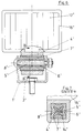
- FIG. 6 shows a middle vertical section through the holder which carries an auxiliary headlamp serving as working headlamps
- FIG. 7 shows a section along the line BB of Figure 6.
- an extension (4 ') is molded onto a lower side wall of a cup-shaped housing (16') made of plastic of the worklight.
- the cup-shaped housing (16 ') is closed by a translucent cover plate (17'), and a reflector (not shown) is inserted into the interior of the headlight formed by the cup-shaped housing (16 ') and the cover plate (17').
- the side wall of the housing (16 ') integrally formed on the extension (4') is tubular through a through opening (5 ') and has a square inside and outside in its cross section.
- a sleeve-shaped spacer (6 ') which is made of metal and is clamped between the legs (2') of a U-shaped bracket (3 '), is arranged in the through opening (5').
- the size of the clamping force depends on the torque with which a screw bolt (8 ') is mounted, which leads through the sleeve-shaped spacer (6') and openings of the leg (2 ') of the U-shaped holder (3').
- ribs (14 ') extending in its longitudinal extent and evenly distributed over its circumference are formed on the outer surface of the sleeve-shaped spacer (6').
- An elastic sleeve (7 ') is pushed onto the sleeve-shaped spacer (6'), the opening of which passes through it corresponds in cross section to the cross section of the spacer (6 ') on its outside.
- the elastic sleeve (7 ') has a star-shaped cross-section with four teeth, with which the sleeve (7') rests under prestress on the corner areas of the through-opening (5 '), which is square in cross-section, of the extension (4').
- the approach (4 ') of the auxiliary headlamp is rotatably connected to the rigid spacer (6') and thus to the U-shaped bracket, since the spacer sleeve (6 ') with the ribs (14') in corresponding slots in the inside of the engages elastic sleeve and the elastic sleeve (7 ') with its outer serrations in the corners of the through-opening (5') of the attachment which is square in cross section (4 ') engages. So that the elastic connection between the spacer sleeve (6 ') and the shoulder (4') is free of play, the spacer (6 ') must be pushed into the elastic sleeve with a press fit.
- the object of the invention is to design the holder described in the preamble of claim 1 for an adjustable mounting of headlights, in particular vehicle headlights, in such a way that the elastic sleeve can be pushed onto the screw bolt with play and can also be inserted into the through opening with play and nevertheless the elastic connection between the U-shaped bracket and the attachment rigidly connected to the headlight is sufficiently firm.
- the size of the vibration damping provided by the elastic connection should always be the same size even if the screw bolt is mounted with a different torque.
- the elastic connection between the legs of the U-shaped bracket and the attachment rigidly connected to the headlight At least two elastic sleeves are made, between which a shoulder formed on the inside of the through opening is arranged, wherein each elastic sleeve with firm contact of the leg on the sleeve-shaped spacer between one of the two legs of the U-shaped bracket and the shoulder of the approach in the direction the pivot axis is compressed.
- the elastic sleeves After mounting the holder, the elastic sleeves are always pressed together in exactly the same way, since the legs of the U-shaped bracket can only be moved so far by the screw bolt that they clamp the sleeve-shaped spacer between them.
- the elastic sleeves can also be installed with very hard elastic material, since they can be pushed onto the spacer with play as well as inserted into the through opening with play. Studies have shown that when a hard rubber is used for the elastic sleeves, not only is the headlight carried largely free of vibration when driving, but the life of the light source is still very long if a lamp with a filament serves as a light source and impacts can be absorbed against the headlights by the elastic connection. The course of forces between the U-shaped bracket and the attachment of the headlight takes place exclusively via the elastic sleeves, and of these largely via the shoulder formed on the inside of the through opening of the attachment.
- the shoulder divides the through opening into two sections of equal length, is designed in a ring shape and is integrally formed on the inside of the through opening.
- the same elastic spacers can be used for both sections, and the contact surface of the shoulder for the elastic sleeves can be made as large as possible.
- the rotationally fixed connection between the headlight and the elastic sleeve is very secure.
- the shoulder is without additional lockable tool parts must be demouldable inside the through opening.
- the spacer passes with play through the section of the through-opening having the shoulder and the elastic sleeves protrude from the through-opening with the end sections facing the legs of the U-shaped bracket.
- the major part of the elastic sleeves is arranged inside the passage opening, protected from daylight, which slows down the aging process of the elastic sleeves.
- annular disk is inserted between the elastic sleeves and the leg of the U-shaped bracket that is adjacent to them and which clamps the spacer between them and which compress the elastic sleeves, without being firmly attached to the headlight attachment to lie on.
- the spacer is made in two parts and each part of the spacer has the same length and is made in one piece with the annular disk made of plastic adjoining it.
- Such a solution can be produced very inexpensively, since the same plastic part can be used for the two disks and the part of the spacer molded onto them.
- the sleeve-shaped plastic part is also much cheaper to produce than a sleeve-shaped spacer made of metal by die casting.
- the disks with their outer circumferential edge project radially beyond the elastic sleeves and are circumferentially a small distance from the attachment.
- interlocking fastening elements between the sleeve and the shoulder of the neck and also between the sleeve and the disk adjoining the sleeve produce a rotationally fixed connection between the disks and the neck of the headlight.
- radially extending slots and ribs engaging in the slots serve as fastening elements, the slots being formed in the elastic sleeves and the corresponding ribs being formed on the shoulder and the disks. This ensures a non-rotatable connection between the headlight and the U-shaped bracket. The connection is very non-rotatable even if the elastic sleeves are made of a soft, elastic material.
- the elastic sleeves which are compressed between the legs of the U-shaped bracket, bear with their outer surface under prestress against the inside of the through opening of the attachment. This not only increases the non-rotatable connection between the headlight and the U-shaped bracket, and it changes its vibration behavior when it hits the headlight.
- the worklight has a cup-shaped housing (16) made of plastic, which is closed off by a translucent cover plate (17).
- a reflector (not shown) with an incandescent lamp is inserted into the headlight interior formed by the pot-shaped housing (16) and the translucent cover plate (17).
- the pot-shaped housing (16) can be connected on its lower side wall by a holder to a vehicle body (not shown).
- the holder has a tubular extension (4) molded onto the lower side wall of the housing (16), the longitudinal axis of which extends transversely to the optical axis of the headlight.
- an annular shoulder (9) is integrally formed on the inside of its through opening (5).
- a sleeve (7) inserted into the through opening (5) of the extension (4), which is made of elastic material, such as. B. rubber, is flat.
- the clear width of the through opening (5) in the region of the shoulder (9) is approximately as large as the clear width of the elastic sleeves (7).
- the outer sides of the extension (4) adjoining the through opening (5) run parallel to one another.
- the elastic sleeves (7) seen transversely to their longitudinal axis, are spherical on their outer surface and protrude with their outwardly directed end sections from the through opening (5) of the extension (4).
- the two elastic sleeves (7) is from each open side Through opening (5) a part of a sleeve-shaped spacer (6) is inserted, which passes with play through the shoulder (6) section of the through opening (5).
- the two parts of the spacer (6) are of the same size and are made in one piece from plastic with an annular disk (11) lying flat against the outer end face of the elastic sleeve (7).
- One leg (2) of a U-shaped bracket (3) made of sheet metal bears against the annular surfaces of the disks (11) pointing away from the shoulder (4).
- a screw bolt (8) is passed through openings in the legs (2) and through the two parts of the sleeve-shaped spacer (6), with little play between the spacers (6) and the screw bolt (8).
- the screw bolt (8) rests with one head on one leg (2) of the U-shaped bracket (3) and protrudes from the opening of the other leg with a threaded shaft, on which a nut is screwed with the interposition of a locking ring.
- the nut (18) is to be assembled with such a large torque until the facing end faces are in contact with the two parts of the spacer.
- the elastic sleeves (7) are compressed between the shoulder (9) of the extension (4) and the washers (11) in the direction of the longitudinal axis of the screw bolt (8).
- the elastic sleeves can be compressed so much that they also bear with their crowned outer surface under tension on the inside of the through opening (5). So that there is a secure, rotationally fixed connection between the headlight and the U-shaped bracket (3) of the holder, there are both between the shoulder (9) of the extension (4) and the elastic sleeves (7) and between the washers (11 ) and the elastic sleeves (7) interlocking fastening elements (11, 12, 13, 14).
- the fastening elements (11 and 14) are radially extending ribs, the ribs (11) being formed on both sides of the shoulder (9) and being uniformly distributed over their annular surface and the ribs (14) being attached to the Approach (4) facing the annular surface of the discs (11) and the outer surface of the spacer (6) are formed and are evenly distributed over the entire annular surface.
- the fastening elements (12 and 13) are slots which are made in the end sections of the elastic sleeve (7).
- the slots (12) of the elastic sleeve (7) are made in their outer edge area and are pushed onto the ribs (11) of the shoulder (9).
- the ribs (14) of the disks (11) engage in the slots (13) of the elastic sleeve (7).
- the slots (13) are made in the inner edge region of the elastic sleeve (7). With their outer circumferential edge, the annular disks (11) project beyond the elastic sleeves (7) and, together with the attachment (4), form a circumferential small gap.
- An opening is made centrally in the web (3) of the holder (1) connecting the legs (2) and a screw (19) is used to fasten the headlight to a vehicle body.
Landscapes
- Engineering & Computer Science (AREA)
- Mechanical Engineering (AREA)
- Lighting Device Outwards From Vehicle And Optical Signal (AREA)
- Non-Portable Lighting Devices Or Systems Thereof (AREA)
Priority Applications (1)
| Application Number | Priority Date | Filing Date | Title |
|---|---|---|---|
| SI9430061T SI0656280T1 (en) | 1993-11-22 | 1994-11-02 | Support for adjustable headlight particularly for vehicle |
Applications Claiming Priority (2)
| Application Number | Priority Date | Filing Date | Title |
|---|---|---|---|
| DE4339687A DE4339687C1 (de) | 1993-11-22 | 1993-11-22 | Halter für eine verstellbare Lagerung von Scheinwerfern, insbesondere Fahrzeugscheinwerfern |
| DE4339687 | 1993-11-22 |
Publications (3)
| Publication Number | Publication Date |
|---|---|
| EP0656280A2 true EP0656280A2 (fr) | 1995-06-07 |
| EP0656280A3 EP0656280A3 (fr) | 1995-11-02 |
| EP0656280B1 EP0656280B1 (fr) | 1997-07-16 |
Family
ID=6503094
Family Applications (1)
| Application Number | Title | Priority Date | Filing Date |
|---|---|---|---|
| EP94117255A Expired - Lifetime EP0656280B1 (fr) | 1993-11-22 | 1994-11-02 | Support pour phare orientable en particulier pour véhicule |
Country Status (5)
| Country | Link |
|---|---|
| EP (1) | EP0656280B1 (fr) |
| AT (1) | ATE155403T1 (fr) |
| DE (1) | DE4339687C1 (fr) |
| ES (1) | ES2104250T3 (fr) |
| SI (1) | SI0656280T1 (fr) |
Families Citing this family (2)
| Publication number | Priority date | Publication date | Assignee | Title |
|---|---|---|---|---|
| JP3423494B2 (ja) * | 1995-07-25 | 2003-07-07 | 株式会社ニフコ | 留め具 |
| DE19756635B4 (de) * | 1996-12-21 | 2005-12-15 | Knecht Maschinenbau Gmbh | Messerbolzen zur drehfesten Positionierung eines Kuttermessers an einer Treibscheibe |
Family Cites Families (2)
| Publication number | Priority date | Publication date | Assignee | Title |
|---|---|---|---|---|
| DE3801500A1 (de) * | 1988-01-20 | 1989-08-03 | Hella Kg Hueck & Co | Halter fuer eine verstellbare lagerung von scheinwerfern |
| DE4126112C1 (fr) * | 1991-08-07 | 1992-12-17 | Hella Kg Hueck & Co, 4780 Lippstadt, De |
-
1993
- 1993-11-22 DE DE4339687A patent/DE4339687C1/de not_active Expired - Fee Related
-
1994
- 1994-11-02 EP EP94117255A patent/EP0656280B1/fr not_active Expired - Lifetime
- 1994-11-02 SI SI9430061T patent/SI0656280T1/xx unknown
- 1994-11-02 ES ES94117255T patent/ES2104250T3/es not_active Expired - Lifetime
- 1994-11-02 AT AT94117255T patent/ATE155403T1/de not_active IP Right Cessation
Also Published As
| Publication number | Publication date |
|---|---|
| EP0656280B1 (fr) | 1997-07-16 |
| DE4339687C1 (de) | 1995-01-26 |
| ES2104250T3 (es) | 1997-10-01 |
| EP0656280A3 (fr) | 1995-11-02 |
| SI0656280T1 (en) | 1997-12-31 |
| ATE155403T1 (de) | 1997-08-15 |
Similar Documents
| Publication | Publication Date | Title |
|---|---|---|
| DE102013202582B4 (de) | Toleranzausgleichsvorrichtung | |
| EP0623413B1 (fr) | Dispositif de serrage rapide pour lames de scie sauteuse | |
| DE102012011848A1 (de) | Befestigungsanordnung | |
| EP1216881B1 (fr) | Elément d'ajustage pour fixer un ensemble de phare sur un véhicule | |
| EP0380908B1 (fr) | Plaque de base en matière plastique | |
| DE4310048C2 (de) | Verfahren zum Befestigen einer lichtdurchlässigen Abschlußscheibe an einem Tragelement einer Leuchte, insbesondere eines Fahrzeugscheinwerfers | |
| EP1884382A1 (fr) | Amortisseur d'oscillations doté d'une fixation | |
| EP0726410B1 (fr) | Support amortisseur de vibrations sur un moteur à combustion interne | |
| EP0656280B1 (fr) | Support pour phare orientable en particulier pour véhicule | |
| DE10315140A1 (de) | Ausrichtvorrichtung für einen Scheinwerfer | |
| DE4228889A1 (de) | Scheinwerfer für Fahrzeuge | |
| EP3133305A1 (fr) | Écrou cage | |
| DE4403974A1 (de) | Gewindemutter zur Schnellbefestigung | |
| DE3801500C2 (fr) | ||
| DE4242439C1 (de) | Befestigungsvorrichtung, insbesondere für Leuchten, vorzugsweise für Kraftfahrzeugleuchten | |
| DE19811165A1 (de) | Positionierelement zur Ausrichtung von Karosserieteilen | |
| DE4126112C1 (fr) | ||
| DE19701371B4 (de) | Einrichtung zur Befestigung eines Reserverades in einer Reserveradmulde eines Kraftfahrzeugs | |
| EP0992728B1 (fr) | Dispositif de retenue pour objets oblongs tel que tuyaux rigides ou flexibles | |
| DE10039679B4 (de) | Anordnung zur Befestigung eines Bauteils an einer Montageplatte | |
| DE10102136A1 (de) | Befestigungdsystem | |
| DE69305951T2 (de) | Einstellbare Befestigungsvorrichtung für eine Gewindeverbindung | |
| DE1680221A1 (de) | Betaetigungsvorrichtung fuer eine Fahrzeugbremse | |
| EP0675021A2 (fr) | Dispositif de fixation d'un réflecteur ajustable pour phare de véhicule | |
| DE10107581B4 (de) | Vorrichtung zur Verbindung eines Kunststoffteils mit einem flachen Trägerteil |
Legal Events
| Date | Code | Title | Description |
|---|---|---|---|
| PUAI | Public reference made under article 153(3) epc to a published international application that has entered the european phase |
Free format text: ORIGINAL CODE: 0009012 |
|
| AK | Designated contracting states |
Kind code of ref document: A2 Designated state(s): AT ES FR GB IT SE |
|
| RAX | Requested extension states of the european patent have changed |
Free format text: SI PAYMENT 941110 |
|
| PUAL | Search report despatched |
Free format text: ORIGINAL CODE: 0009013 |
|
| AK | Designated contracting states |
Kind code of ref document: A3 Designated state(s): AT ES FR GB IT SE |
|
| 17P | Request for examination filed |
Effective date: 19960306 |
|
| GRAG | Despatch of communication of intention to grant |
Free format text: ORIGINAL CODE: EPIDOS AGRA |
|
| GRAG | Despatch of communication of intention to grant |
Free format text: ORIGINAL CODE: EPIDOS AGRA |
|
| 17Q | First examination report despatched |
Effective date: 19961119 |
|
| GRAH | Despatch of communication of intention to grant a patent |
Free format text: ORIGINAL CODE: EPIDOS IGRA |
|
| ITF | It: translation for a ep patent filed | ||
| GRAH | Despatch of communication of intention to grant a patent |
Free format text: ORIGINAL CODE: EPIDOS IGRA |
|
| GRAA | (expected) grant |
Free format text: ORIGINAL CODE: 0009210 |
|
| AK | Designated contracting states |
Kind code of ref document: B1 Designated state(s): AT ES FR GB IT SE |
|
| AX | Request for extension of the european patent |
Free format text: SI PAYMENT 941110 |
|
| REF | Corresponds to: |
Ref document number: 155403 Country of ref document: AT Date of ref document: 19970815 Kind code of ref document: T |
|
| REG | Reference to a national code |
Ref country code: ES Ref legal event code: FG2A Ref document number: 2104250 Country of ref document: ES Kind code of ref document: T3 |
|
| GBT | Gb: translation of ep patent filed (gb section 77(6)(a)/1977) |
Effective date: 19970919 |
|
| ET | Fr: translation filed | ||
| PLBE | No opposition filed within time limit |
Free format text: ORIGINAL CODE: 0009261 |
|
| STAA | Information on the status of an ep patent application or granted ep patent |
Free format text: STATUS: NO OPPOSITION FILED WITHIN TIME LIMIT |
|
| 26N | No opposition filed | ||
| PGFP | Annual fee paid to national office [announced via postgrant information from national office to epo] |
Ref country code: GB Payment date: 20001024 Year of fee payment: 7 |
|
| PGFP | Annual fee paid to national office [announced via postgrant information from national office to epo] |
Ref country code: SE Payment date: 20001124 Year of fee payment: 7 |
|
| PG25 | Lapsed in a contracting state [announced via postgrant information from national office to epo] |
Ref country code: GB Free format text: LAPSE BECAUSE OF NON-PAYMENT OF DUE FEES Effective date: 20011102 |
|
| PG25 | Lapsed in a contracting state [announced via postgrant information from national office to epo] |
Ref country code: SE Free format text: LAPSE BECAUSE OF NON-PAYMENT OF DUE FEES Effective date: 20011103 |
|
| PGFP | Annual fee paid to national office [announced via postgrant information from national office to epo] |
Ref country code: ES Payment date: 20011114 Year of fee payment: 8 |
|
| PGFP | Annual fee paid to national office [announced via postgrant information from national office to epo] |
Ref country code: FR Payment date: 20011122 Year of fee payment: 8 |
|
| PGFP | Annual fee paid to national office [announced via postgrant information from national office to epo] |
Ref country code: AT Payment date: 20011123 Year of fee payment: 8 |
|
| REG | Reference to a national code |
Ref country code: GB Ref legal event code: IF02 |
|
| GBPC | Gb: european patent ceased through non-payment of renewal fee |
Effective date: 20011102 |
|
| EUG | Se: european patent has lapsed |
Ref document number: 94117255.3 |
|
| PG25 | Lapsed in a contracting state [announced via postgrant information from national office to epo] |
Ref country code: AT Free format text: LAPSE BECAUSE OF NON-PAYMENT OF DUE FEES Effective date: 20021102 |
|
| PG25 | Lapsed in a contracting state [announced via postgrant information from national office to epo] |
Ref country code: ES Free format text: LAPSE BECAUSE OF NON-PAYMENT OF DUE FEES Effective date: 20021103 |
|
| PG25 | Lapsed in a contracting state [announced via postgrant information from national office to epo] |
Ref country code: FR Free format text: LAPSE BECAUSE OF NON-PAYMENT OF DUE FEES Effective date: 20030731 |
|
| REG | Reference to a national code |
Ref country code: FR Ref legal event code: ST |
|
| REG | Reference to a national code |
Ref country code: ES Ref legal event code: FD2A Effective date: 20031213 |
|
| PG25 | Lapsed in a contracting state [announced via postgrant information from national office to epo] |
Ref country code: IT Free format text: LAPSE BECAUSE OF NON-PAYMENT OF DUE FEES;WARNING: LAPSES OF ITALIAN PATENTS WITH EFFECTIVE DATE BEFORE 2007 MAY HAVE OCCURRED AT ANY TIME BEFORE 2007. THE CORRECT EFFECTIVE DATE MAY BE DIFFERENT FROM THE ONE RECORDED. Effective date: 20051102 |