EP0656292A1 - Sandstreuer mit einem Behälter, der granuliertes Material, insbesondere Sand, enthält für ein Rad eines Triebwagens - Google Patents
Sandstreuer mit einem Behälter, der granuliertes Material, insbesondere Sand, enthält für ein Rad eines Triebwagens Download PDFInfo
- Publication number
- EP0656292A1 EP0656292A1 EP94402587A EP94402587A EP0656292A1 EP 0656292 A1 EP0656292 A1 EP 0656292A1 EP 94402587 A EP94402587 A EP 94402587A EP 94402587 A EP94402587 A EP 94402587A EP 0656292 A1 EP0656292 A1 EP 0656292A1
- Authority
- EP
- European Patent Office
- Prior art keywords
- sandblaster
- probe
- piston
- granular material
- container
- Prior art date
- Legal status (The legal status is an assumption and is not a legal conclusion. Google has not performed a legal analysis and makes no representation as to the accuracy of the status listed.)
- Withdrawn
Links
- 239000004576 sand Substances 0.000 title claims description 40
- 239000008187 granular material Substances 0.000 claims abstract description 26
- 239000000523 sample Substances 0.000 claims description 45
- 239000012530 fluid Substances 0.000 claims description 26
- 239000000463 material Substances 0.000 claims description 8
- 230000000007 visual effect Effects 0.000 claims description 4
- 238000001035 drying Methods 0.000 claims description 3
- 238000011001 backwashing Methods 0.000 claims description 2
- 238000006073 displacement reaction Methods 0.000 claims 1
- 238000007689 inspection Methods 0.000 description 4
- 241001508691 Martes zibellina Species 0.000 description 3
- 230000005484 gravity Effects 0.000 description 3
- 238000007789 sealing Methods 0.000 description 3
- 238000009434 installation Methods 0.000 description 2
- 230000001154 acute effect Effects 0.000 description 1
- 239000003795 chemical substances by application Substances 0.000 description 1
- 230000005574 cross-species transmission Effects 0.000 description 1
- 238000001914 filtration Methods 0.000 description 1
- 238000012423 maintenance Methods 0.000 description 1
- 238000012986 modification Methods 0.000 description 1
- 230000004048 modification Effects 0.000 description 1
- 239000007921 spray Substances 0.000 description 1
- XLYOFNOQVPJJNP-UHFFFAOYSA-N water Substances O XLYOFNOQVPJJNP-UHFFFAOYSA-N 0.000 description 1
Images


Classifications
-
- G—PHYSICS
- G01—MEASURING; TESTING
- G01F—MEASURING VOLUME, VOLUME FLOW, MASS FLOW OR LIQUID LEVEL; METERING BY VOLUME
- G01F23/00—Indicating or measuring liquid level or level of fluent solid material, e.g. indicating in terms of volume or indicating by means of an alarm
- G01F23/14—Indicating or measuring liquid level or level of fluent solid material, e.g. indicating in terms of volume or indicating by means of an alarm by measurement of pressure
- G01F23/16—Indicating, recording, or alarm devices being actuated by mechanical or fluid means, e.g. using gas, mercury, or a diaphragm as transmitting element, or by a column of liquid
- G01F23/161—Indicating, recording, or alarm devices being actuated by mechanical or fluid means, e.g. using gas, mercury, or a diaphragm as transmitting element, or by a column of liquid for discrete levels
-
- B—PERFORMING OPERATIONS; TRANSPORTING
- B61—RAILWAYS
- B61C—LOCOMOTIVES; MOTOR RAILCARS
- B61C15/00—Maintaining or augmenting the starting or braking power by auxiliary devices and measures; Preventing wheel slippage; Controlling distribution of tractive effort between driving wheels
- B61C15/08—Preventing wheel slippage
- B61C15/10—Preventing wheel slippage by depositing sand or like friction increasing materials
- B61C15/102—Preventing wheel slippage by depositing sand or like friction increasing materials with sanding equipment of mechanical or fluid type, e.g. by means of steam
Definitions
- the invention relates to a sandblaster comprising a container containing a granular material, in particular sand, the container being adapted at the bottom to cooperate with an orifice with controlled opening to allow, when desired, the flow of the granular material. .
- the invention relates more particularly, because it is in this case that its application seems to be of most interest, but not exclusively, such a sandblaster associated with a drive wheel.
- a sandblaster is intended, during emergency or normal braking to avoid slippage, to spread sand on the railway rail, below the braked wheel, to increase efficiency braking and reduce the stopping distance.
- the sandblaster is also used during start-up to improve grip.
- the sandblaster container generally contains a sufficient quantity of sand to be poured out during the entire duration of braking leading to a complete stop of the train, from its maximum possible speed on the route in question, or a start.
- the subject of the present invention is a compact sandblaster which is easy to maintain and does not require disassembly of the assembly in order to access the essential functional parts, while allowing the sanding operation to be carried out in an optimum manner, and to prevent any untimely emptying of the sand; such a sandblaster can also be arranged so that it allows mixing and drying of the sand, and that it can receive, without modification, a sand level detector.
- a sandblaster comprising a container containing a granular material, the container being adapted at the bottom to cooperate with an orifice with controlled opening to allow, when desired, the flow of the granular material, is characterized by the fact that the sandblaster comprises a base carrying the controlled opening orifice and supporting on one side, the lower side, a body carrying a material distribution pipe granular, to distribute it in a desired location, and on the other side the opening opening control means which are also contained in the container, the body being fixed to the base in a removable manner.
- the means for controlling the opening of the orifice are implemented by means of a fluid under hydraulic or pneumatic pressure, and consist of a cylinder block with vertical axis receiving in leaktight sliding a piston of the differential type having two sections corresponding respectively one to that of a piston tail, the other to that of a piston head, the tail having a section larger than that of the head and being disposed at the upper part of the block cylinder.
- the orifice is carried by an annular flow seat placed in the axis of a seat seat of conical shape whose concavity is turned towards the reservoir and with which a circular valve formed at the end of the piston head; the seat surface is provided at the periphery of a closure seat which supports the flow seat, the flow seat being accessible from the outside when the body is removed from the base.
- the body has a passage opening at its upper part to the right of the orifice and connected at its lower part to a passage, inclined with respect to said passage and connected to the distribution pipe.
- the cylinder block is supplied with pressurized fluid by a conduit, the major part of which is constituted by the interior of a recessed tube, sealed at each of its ends, in the cylinder block, on the one hand , and in the base, on the other hand; the base is pierced with a duct connected, on one side, to a source of pressurized fluid and, on the other side, to the supply duct of the cylinder block via a channel and passages formed in the body.
- the body carries a nozzle intended to receive pressurized fluid and to direct a jet of this fluid towards the distribution manifold; alternatively, or in combination, the piston is provided with an axial passage comprising a calibrated passage in the axis of the orifice, the calibrated passage being intended to receive pressurized fluid and to direct a jet of this fluid towards the distribution pipe.
- the base is pierced with a conduit which opens internally inside the container, air blown into said conduit allowing the backwashing and drying of the sand contained in the container.
- the sandblaster is equipped with a detector of the level of the granular material contained in the container.
- the subject of the invention is also a level detector inside a container containing a granular material, in particular sand, the container comprising in the lower part an orifice with controlled opening to allow, when desired, the flow of granular material.
- the invention relates more particularly, because it is in this case that its application seems to be of most interest, but not exclusively, such a level detector for a sandblaster associated with a drive wheel.
- a problem which the invention aims to solve is that of providing, in a simple manner, a reliable indication of the level of a granular material inside a container.
- the safety threshold inside the sandblaster, corresponds to an amount of sand sufficient to pour out during the entire duration of braking leading to a complete stop of the train, from its maximum possible speed on the route considered, or a start.
- these means for exerting a force on the probe are pneumatic means.
- a push button intended to be actuated manually, is provided for controlling these pneumatic, or electro-pneumatic means.
- Said pneumatic means may comprise a piston linked to the probe, the pressurized fluid being admitted from the side of the piston opposite the probe so that, when this pressurized fluid is sent to the piston, the piston is biased towards the granular material .
- the probe is advantageously associated with a distributor capable of controlling the warning means by sending a pressurized fluid to these warning means when the movement of the probe and of the distributor linked to this probe is sufficient; the piston associated with the probe is arranged so that it plays the role of said distributor.
- the warning means may include a visual indicator capable of projecting under the action of a pressurized fluid when the operator presses the push button and the probe moves sufficiently, due to a lower level of granular material. at the safety limit; the warning means can also be light or sound means, by adding a signal transformer device.
- the push-button can be recalled to the rest position by elastic means and, in this rest position, the push-button ensures the atmosphere in the working chamber which controls the movement of the visual indicator means.
- the probe can be secured to an adjustable screw urged by an elastic means recalling the probe in the rest position.
- the detector is mounted on the upper part of the sandblaster, and the detector and the sandblaster are connected to the same source of pressurized fluid.
- the warning means and the push button are carried by the same block connected by pipes to the sandblaster and to the source of pressurized fluid.
- the flow seat is made of flexible material and can swallow larger grains of sand than its theoretical passage section.
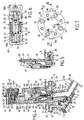
- the sandblaster 2 comprises a base 30 carried by the chassis 7 of the powerplant, which supports the container R containing sand 1; integral with the base 30, a body 10 is pressed against the underside of said base 30.
- the body 10 is a cast part defining various conduits.
- a conduit 11 terminated by a collar 16 for connection to the distribution pipe 6 internally carries a cylindrical jacket 13A defining a passage 13; the inclination of the conduit 11 corresponds to the desired inclination of the tubing 6.
- the conduit 11 communicates, via a chamber C1, with a conduit 12 formed in the upper part of the body 10 to which it opens at the outside of the body 10 by crossing a horizontal plate 15 which borders the body 10; the duct 12, slightly inclined towards the duct 11, with respect to the vertical, internally carries a cylindrical jacket 14A defining another passage 14.
- the body 10 defines a chamber C2; the chambers C1 and C2 are produced in housings of the body 10 which open to the outside through openings which are closed in leaktight manner by an inspection door 18; the inspection door 18 maintains a shutter 17 mounted in said opening corresponding to the chamber C1, and a filter element 22 disposed completely across the chamber C2 perpendicularly to the inspection door 18.
- the plate 15 of the body 10 and the base 30 have a generally circular section; the base 30 is pierced with two blind conduits 31 and 33 extending radially and diametrically opposite.
- the conduit 31 is connected externally to a pipe 203 and internally to the chamber C2 via a channel 25 formed in the body 10; of course, the conduit 31 could also be connected externally to the chamber C2.
- the conduit 33 is externally connected to a pipe 206, itself connected to the pipe 203, and opens internally inside the container R, at the bottom of the latter.
- the piping 203 is connected, via a switch 202, to the outlet 201 of an air compressor 200.
- the base 30 is crossed at its center by a closing seat 34 of annular shape provided with a seat bearing 36 of conical shape whose concavity is turned towards the reservoir R; the closing seat 34 carries in its center, below the seat span 36 an annular flow seat 35 of cross section in the form of a diabolo; when the base 30 and the body 10 are assembled, the closing 34 and flow 35 seats are in line with the passage 14; it is the flow seat 35 which carries the orifice 5.
- the flow seat 35 is made of flexible material: thus, it is possible for it to swallow grains of sand larger than its theoretical passage section.
- a cylinder block 41 held in place at a distance from the base 30 by vertical tie rods threaded at the two ends, not shown, coupled, on the one hand, to the cylinder block 41 and, on the other hand, at base 30.
- the cylinder block 41 receives, in leaktight sliding, a piston 40 of the differential type, in a bore 42 also of the differential type: the two sections of the differential piston 40 correspond one to that of a piston tail 43, the other to that of a piston head 44, seals being placed respectively between the tail 43 and the head 44, on the one hand, and the bore 42, on the other hand; the tail 43 has a larger section than that of the head 44 and is disposed at the upper part of the cylinder block 41.
- the head 44 of the piston 40 ends, opposite the tail 43, in the form of a circular valve 46; the head 44 of the piston 40 has a sufficient length so that, when the piston 40 is in the low position, as shown in FIG. 1A, the valve 46 is brought to cooperate with the conical bearing surface 36 of the closing seat 34, thus closing the orifice 5 through which the sand 1 is prevented from flowing; the piston 40 is biased in this position by a spring 40A disposed between the tail 43 of the piston 40 and a cover 49A, secured to the cylinder block 41 by being pressed against the front face 49 thereof, which closes the bore 42 A bellows 84 protects the piston 1 from sliding against the sand 1.
- the opening control of the orifice 5, that is to say the lifting control, relative to the position shown in FIG. 1A, of the piston 40, is carried out pneumatically from the air compressor 200, which can be the general air compressor allowing the control of various components of the powerplant and / or the associated train, or a particular air compressor dedicated to the sandblaster.
- the air compressor 200 can be the general air compressor allowing the control of various components of the powerplant and / or the associated train, or a particular air compressor dedicated to the sandblaster.
- the pressurization chamber defined by the differential piston 40 and the cylinder block 41 is connected to the chamber C2 of the body 10; this connection is made by a conduit 81, the major part of which is constituted by the inside of a tube 80 embedded with sealing at each of its ends in the cylinder block 41, on the one hand, and in the base 30, d 'somewhere else ; the tube 80 is embedded in the base 30 at the right of a passage 32 which crosses it and at the right of which is provided, in the body 10, a passage 24; the passage 24 communicates with the chamber C2 by a passage 23 surrounded by a coaxial filtering element 22 which extends in the chamber C2, over the entire height thereof, and which is held in place by the inspection door 18 ; around the filter element 22 is disposed a spray guard 21 which extends halfway up the chamber C2.
- the valve 46 has moved away from the conical bearing surface 36 of its seat; the sand 1 descends by gravity through the open orifice 5, the passages 14, 13, the tubing 6 to the rail 4; the compressed air deflected by the piping 206 to the duct 33, or brought by an internal circuit connecting the duct 31 to the duct 33, acts at the base of the sand 1 to loosen it and facilitate its descent by gravity; in addition, the sand 1 being brewed it is dried if necessary.
- the removable flow seat 35 allows the sand flow to be adapted to any type of machine or course. It will have been noted, moreover, that in the closed position, as represented in FIG. 1A, the sandblaster is completely closed: thus, any untimely emptying of the sand is prevented, even at very high speed, as well as any ascent of water or moisture.
- the invention also provides for rapid movement of the sand 1 towards the wheel 3; for this purpose, the passage 24 of the body 10 also communicates with the chamber C1 via a nozzle 20 which opens along the axis of the passage 13 and which is formed in a diffuser 19 mounted in leaktight manner in a housing which passes through a veil of the body 10 separating the chambers C1 and C2. Thanks to this arrangement, a compressed air flow passes through the chamber C1, the passage 24, the nozzle 20 and pushes the sand 1, which flows in the passage 14, towards the wheel 3.
- the differential piston 40 is provided with an axial passage 45 in communication, on one side, with the chamber defined by the differential piston 40 and the cylinder block 41 and , on the other side, with the exterior; at its end towards the outside, the axial passage 45 is provided with a rod 47 crossed axially by a hollow needle and defining a calibrated passage 48 in the axis of the orifice 5; thus, a compressed gas flow also passes through from passage 24, passage 32, conduit 81, axial passage 45, calibrated passage 48 and orifice 5, such a current of air pushing sand 1 into the passage 14 to wheel 3; the rod 47 allows the breaking of possible agglomerates of sand, due to humidity for example, and the discharge of these towards the outside, the passage of the orifice 5 of the flow seat 35 being thereby freed .
- the sandblaster which has just been described is adapted to be equipped, if desired, with a device making it possible to detect whether the level of the sand 1 contained in the container R is above, equal to or below a level reference N, or safety threshold, which corresponds to an amount of sand sufficient to spill over the entire duration braking or starting on a route in question.
- the sander thus equipped is shown in Figures 2 to 8.
- the level detector D comprises a housing 60; the housing 60 is designed to support a mobile assembly 50 mounted to slide in the housing 60.
- the mobile assembly 50 comprises a probe 50A projecting outside the housing 60 and to which a piston 50B is coupled coaxially secured to the probe 50A by a connecting screw 59, the common axis of the probe 50A and of the piston 50B being horizontal. Furthermore, extending parallel to said axis, a screw called a feeler screw 50C, having a head 53, is screwed into the feeler in an adjustable manner, the feeler screw 50C and the piston 50B extend parallel on the same side with respect to to the probe 50A; in FIGS. 2 and 3, the mobile assembly consisting of the probe 50A, the piston 50B and the probe screw 50C has been shown in one piece so as not to make it difficult to read these figures, given their reduced scale compared to that of Figure 4.
- the housing 60 To receive the moving element 50, the housing 60 has a cylinder housing 70 with a horizontal axis opening on one side to the outside and on the other in a pressure chamber 69, blind and of section slightly smaller than that of the cylinder housing 70 so that an annular abutment shoulder is defined against which a distribution cylinder 67 of generally tubular shape and mounted in sealing, by means of a seal 74, is supported in the cylinder housing 70.
- the cylinder distribution 67 is held in this position by a bearing 57 fixed by a retaining screw 58 to the housing 60 and cooperating with the skirt-like end of the distribution cylinder 67, opposite to the pressure chamber 69; the bearing 57 extends to the right of the cylindrical housing 68 which it covers while leaving, in the axis of said cylindrical housing 68, a screw passage 63 intended to receive the probe 50C with free sliding; the other end of the cylindrical housing 68 is closed by a plug 72 screwed into the housing 60: this allows, by removing the plug 72 to have access to the head 53 of the feeler screw 50C; a screw spring 54 is placed around the probe screw 50C and placed between the screw head 53 and the bearing 57.
- the bearing 57 is pierced in its center with a bore of internal diameter equal to that of the distribution cylinder 67 and of the same axis so as to receive the piston 50B in leaktight sliding: a sealing point 62 is carried by the piston 50B to cooperate with the distribution cylinder 67.
- the piston 50B and the distribution cylinder 67 are arranged to constitute distribution means associated with the probe 50A; as can be seen in FIG. 4 and the partial section of FIG. 8, in the left-most position, in these figures, in which the probe 50A is in abutment against the bearing 57, position towards which it is recalled by the screw spring 54, the free end of the piston 50B extends into the pressure chamber 69.
- This end is provided with a blind axial channel 56, opening into the pressure chamber 69, to which a radial channel 55 is also connected opening into the pressure chamber 69; between the seals 52 and 62, the skirt of the distribution cylinder 67 is at a radial distance from the piston 50B to define a distribution chamber 71.
- the pressure chamber 69 and the distribution chamber 71 are connected, respectively, to a supply passage 61 and a control passage 65 formed in the housing 60 and opening out at the bottom of the housing 60.
- the level detector D which has just been described is placed on the sandblaster 2 after the cover 49A has been removed; the cylinder block 41 of the sandblaster has passages 85, 86 which pass through it arranged so that it is possible to orient the cylinder block 41 above the base 30 so that the passage 85 is located in line with the passage 32 of the base 30 and the passage 86 to the right of the outlet of the conduit 33; thus, the conduit 81 produced by the tube 80 connects the passages 85 and 32; in the same way, a tube 82 providing a conduit 83 connects the passage 86 and the outlet of the conduit 33.
- the level detector D is positioned on the cylinder block 41 of the sandblaster 2 so that the supply passage 61 and the control passage 65 are respectively in line with passages 85 and 86 and, therefore, respectively connected to passage 32 and to conduit 33 of the base 30.
- the mechanical strength of the assembly is achieved by three threaded rods 38 ( Figures 5 and 7) which assemble the housing 60, the cylinder block 41 and the base 30.
- Means 75 of the screw-nut type ensure the attachment of the body 10 at base 30.
- the probe 50A and the piston 50B have a horizontal common axis; according to a variant not shown, said axis is vertical.
- the conduit 33 is intended for the implementation of warning means 100 which will now be described with reference to FIG. 2.
- the warning means 100 are carried by a block 90 which also includes a push button 91 intended to be actuated manually.
- the push button 91 is slidably mounted in a bore 92 of the block 90; the tail 93 of the push button 91 is surrounded by a stop piece 95 which, by cooperating with an internal wall of the block 90, retains the push button 91 in its rest position shown in FIG. 2, towards which it is urged by a spring 94.
- the warning means 100 consist of a piston mounted to slide in a cylindrical housing 102 of the block 90; a spring 101 biases said warning piston 100 in its rest position shown in FIG. 2: in this position, the external face of the warning piston 100 is flush with the front face 105 of the block 90.
- the working face of the warning piston 100 constitutes the movable wall d a control chamber 104 connected by a pipe 206 to the conduit 33 of the base 30.
- the control chamber 104 is also connected by a discharge conduit 99 and a nozzle 107, formed in the block 90, to a discharge chamber 103, itself connected to a discharge channel 96 open towards the outside of the block 90; a closing pin 98 is sliding mounted opposite the nozzle 107; the closing pin 98 is coupled to the stop piece 95, therefore to the push button 91, so that when the push button 91 is actuated and moves to the left, relative to FIG. 2, it drives the closing pin 98 which closes the outlet of the nozzle 107 towards the discharge chamber 103.
- the body of the push button 91 carries an annular recess 106 at its periphery allowing the push button 91 to operate in the manner of a drawer; two pipes 204, 205 open perpendicularly into the bore 92 of the block 90; the other ends of the pipes 204, 205 are respectively connected to the outlet 201 of the air compressor 200 and to the channel 25 of the body 10; the annular recess 106 of the push button 91 is such that in the rest position, FIG.
- the operation is as follows.
- the sandblaster 2 For the implementation of the sandblaster 2, an operator opening the switch 202 sends compressed air into the piping 203 therefore in the conduit 81 and the piston 40 is raised, the valve 46 leaving the conical bearing 36 of the closing seat 34; the orifice 35 is open and the sand 1 flows by gravity towards the tube 6; in parallel, the feed passage 61 is pressurized; the section of the probe 50A of the moving element 50 subjected to the pressure of the sand which surrounds it and the setting of the spring 54 of the probe screw 50C are chosen so that, as long as the level of the sand 1 in the container R is greater than the security level N, the compressed air pressure acting on the piston 50B of the level detector D cannot move the moving element 50; therefore, the warning means 100 are at rest.
- compressed air passes through the nozzle 20 in the body 10 and the calibrated passage of the rod 47 of the head 44 of the piston 40, these two air currents accelerating the emptying of the sand 1 towards the pipe 6.
- This operation is shown in FIG. 2. It will have been noted that it is also possible for the operator to implement the sandblaster 2 by actuating the push button 91 of the block 90 instead of the switch 202; in fact, the movement of the push button 91 connecting the pipes 204, 205, it is through these pipes that the channel 25 is supplied with compressed air.
- the moving element 50 has moved and, therefore, the piping 206 receives a flow of compressed air which passes through the channel of discharge 96 from block 90 via control chamber 104, conduit 99; if the operator acts on the push-button 91, it drives the closing pin 98 which closes the nozzle 107: the control chamber 104 builds up pressure and causes it to spring outside, against the action of the spring 101, the warning piston 100 which, projecting from the front face of the block 90, signals the insufficient level of sand 1 in the container R.
Landscapes
- Engineering & Computer Science (AREA)
- Transportation (AREA)
- Mechanical Engineering (AREA)
- Physics & Mathematics (AREA)
- Fluid Mechanics (AREA)
- General Physics & Mathematics (AREA)
- Nozzles (AREA)
- Fertilizing (AREA)
Applications Claiming Priority (2)
| Application Number | Priority Date | Filing Date | Title |
|---|---|---|---|
| FR9314374A FR2713182B1 (fr) | 1993-12-01 | 1993-12-01 | Sableur comportant un récipient contenant un matériau granuleux, notamment du sable, associé à une roue de motrice. |
| FR9314374 | 1993-12-01 |
Publications (1)
| Publication Number | Publication Date |
|---|---|
| EP0656292A1 true EP0656292A1 (de) | 1995-06-07 |
Family
ID=9453414
Family Applications (1)
| Application Number | Title | Priority Date | Filing Date |
|---|---|---|---|
| EP94402587A Withdrawn EP0656292A1 (de) | 1993-12-01 | 1994-11-16 | Sandstreuer mit einem Behälter, der granuliertes Material, insbesondere Sand, enthält für ein Rad eines Triebwagens |
Country Status (3)
| Country | Link |
|---|---|
| EP (1) | EP0656292A1 (de) |
| ES (1) | ES2073384T1 (de) |
| FR (1) | FR2713182B1 (de) |
Cited By (10)
| Publication number | Priority date | Publication date | Assignee | Title |
|---|---|---|---|---|
| AT403679B (de) * | 1996-06-28 | 1998-04-27 | Goldmann Norbert | Druckluftbetätigte austragseinrichtung für ein streugerät |
| EP1470981A1 (de) * | 2003-04-22 | 2004-10-27 | Zeppenfeld Industrie-Verwaltungs-GmbH | Sandaustragseinrichtung an einem Schienenfahrzeug |
| FR2957321A1 (fr) * | 2010-03-15 | 2011-09-16 | Barba Willy Del | Distributeur de sable pour l'antipatinage des roues des trains |
| WO2013034816A1 (fr) * | 2011-09-08 | 2013-03-14 | Delbarba Willy | Distributeur de sable pour l'antipatinage des roues des trains |
| WO2015055723A1 (de) | 2013-10-15 | 2015-04-23 | Werner Bartling | Dosiereinrichtung für granulat |
| CN104890682A (zh) * | 2015-06-19 | 2015-09-09 | 株洲联诚集团有限责任公司 | 一种自清理细沙粒的机车撒砂器 |
| WO2015189771A1 (en) | 2014-06-10 | 2015-12-17 | Microsistemi S.R.L. | Sandbox for rail vehicles |
| CN110481573A (zh) * | 2019-09-25 | 2019-11-22 | 华铁西屋法维莱(青岛)交通设备有限公司 | 一种具有残砂清理的两级撒砂装置及其气路控制方法 |
| WO2020030559A1 (de) | 2018-08-06 | 2020-02-13 | Nowe Gmbh | Vorrichtung zum streuen von granulat |
| US20240043046A1 (en) * | 2020-12-15 | 2024-02-08 | Siemens Mobility GmbH | Sanding system for a rail vehicle |
Families Citing this family (1)
| Publication number | Priority date | Publication date | Assignee | Title |
|---|---|---|---|---|
| FR2876647B1 (fr) | 2004-10-15 | 2006-12-15 | Snfbo Sa | Ejecteur de materiau granuleux |
Citations (3)
| Publication number | Priority date | Publication date | Assignee | Title |
|---|---|---|---|---|
| GB663674A (en) * | 1949-07-01 | 1951-12-27 | Westinghouse Brake & Signal | Improvements relating to sanding devices for vehicles |
| FR1349653A (fr) * | 1963-02-25 | 1964-01-17 | Sablière à air comprimé pour locomotives | |
| US3782323A (en) * | 1972-06-09 | 1974-01-01 | Bowles Fluidics Corp | Self contained fluidic level sensor |
-
1993
- 1993-12-01 FR FR9314374A patent/FR2713182B1/fr not_active Expired - Fee Related
-
1994
- 1994-11-16 ES ES94402587T patent/ES2073384T1/es active Pending
- 1994-11-16 EP EP94402587A patent/EP0656292A1/de not_active Withdrawn
Patent Citations (3)
| Publication number | Priority date | Publication date | Assignee | Title |
|---|---|---|---|---|
| GB663674A (en) * | 1949-07-01 | 1951-12-27 | Westinghouse Brake & Signal | Improvements relating to sanding devices for vehicles |
| FR1349653A (fr) * | 1963-02-25 | 1964-01-17 | Sablière à air comprimé pour locomotives | |
| US3782323A (en) * | 1972-06-09 | 1974-01-01 | Bowles Fluidics Corp | Self contained fluidic level sensor |
Cited By (22)
| Publication number | Priority date | Publication date | Assignee | Title |
|---|---|---|---|---|
| AT403679B (de) * | 1996-06-28 | 1998-04-27 | Goldmann Norbert | Druckluftbetätigte austragseinrichtung für ein streugerät |
| EP1470981A1 (de) * | 2003-04-22 | 2004-10-27 | Zeppenfeld Industrie-Verwaltungs-GmbH | Sandaustragseinrichtung an einem Schienenfahrzeug |
| DE10318289A1 (de) * | 2003-04-22 | 2004-11-11 | Zeppenfeld Industrie-Verwaltungs-Gmbh | Sandaustragseinrichtung an einem Schienenfahrzeug |
| FR2957321A1 (fr) * | 2010-03-15 | 2011-09-16 | Barba Willy Del | Distributeur de sable pour l'antipatinage des roues des trains |
| WO2013034816A1 (fr) * | 2011-09-08 | 2013-03-14 | Delbarba Willy | Distributeur de sable pour l'antipatinage des roues des trains |
| US9637140B2 (en) | 2013-10-15 | 2017-05-02 | Nowe Gmbh | Metering device for granular material |
| WO2015055723A1 (de) | 2013-10-15 | 2015-04-23 | Werner Bartling | Dosiereinrichtung für granulat |
| AT515060A1 (de) * | 2013-10-15 | 2015-05-15 | Bartling Werner | Dosiereinrichtung für Granulat |
| AT515060B1 (de) * | 2013-10-15 | 2015-08-15 | Bartling Werner | Dosiereinrichtung für Granulat |
| US10029703B2 (en) | 2014-06-10 | 2018-07-24 | Microsistemi S.R.L. | Sandbox for rail vehicles |
| WO2015189771A1 (en) | 2014-06-10 | 2015-12-17 | Microsistemi S.R.L. | Sandbox for rail vehicles |
| CN104890682B (zh) * | 2015-06-19 | 2017-02-01 | 株洲联诚集团有限责任公司 | 一种自清理细沙粒的机车撒砂器 |
| CN104890682A (zh) * | 2015-06-19 | 2015-09-09 | 株洲联诚集团有限责任公司 | 一种自清理细沙粒的机车撒砂器 |
| WO2020030559A1 (de) | 2018-08-06 | 2020-02-13 | Nowe Gmbh | Vorrichtung zum streuen von granulat |
| AT521564A1 (de) * | 2018-08-06 | 2020-02-15 | Nowe Gmbh | Vorrichtung zum Streuen von Granulat |
| CN112512892A (zh) * | 2018-08-06 | 2021-03-16 | 诺维有限公司 | 用于散布颗粒的装置 |
| RU2753376C1 (ru) * | 2018-08-06 | 2021-08-13 | Нове Гмбх | Устройство для разбрасывания гранулированного материала |
| AT521564B1 (de) * | 2018-08-06 | 2022-01-15 | Nowe Gmbh | Vorrichtung zum Streuen von Granulat |
| US12017688B2 (en) | 2018-08-06 | 2024-06-25 | Nowe Gmbh | Device for spreading granulate |
| CN110481573A (zh) * | 2019-09-25 | 2019-11-22 | 华铁西屋法维莱(青岛)交通设备有限公司 | 一种具有残砂清理的两级撒砂装置及其气路控制方法 |
| US20240043046A1 (en) * | 2020-12-15 | 2024-02-08 | Siemens Mobility GmbH | Sanding system for a rail vehicle |
| US11952017B2 (en) * | 2020-12-15 | 2024-04-09 | Siemens Mobility GmbH | Sanding system for a rail vehicle |
Also Published As
| Publication number | Publication date |
|---|---|
| FR2713182B1 (fr) | 1996-02-02 |
| FR2713182A1 (fr) | 1995-06-09 |
| ES2073384T1 (es) | 1995-08-16 |
Similar Documents
| Publication | Publication Date | Title |
|---|---|---|
| FR2713182A1 (fr) | Sableur comportant un récipient contenant un matériau granuleux, notamment du sable, associé à une roue de motrice. | |
| CA1276525C (fr) | Valve d'alimentation d'une capacite puis de decharge brutale de cette capacite | |
| FR2611843A1 (fr) | Ressort a gaz convertible | |
| EP0176442A1 (de) | Verlängerbare Anhängerkupplung für Strassenfahrzeuge und Schienenfahrzeuge | |
| EP0293355B1 (de) | Vorrichtung zur Verriegelungskontrolle eines Seilkernbohrgerätes | |
| EP0883731A1 (de) | Kernbohrwerkzeug | |
| EP0656529A1 (de) | Füllstandssensor | |
| LU88232A1 (fr) | Dispositif de chargement d'une enceinte sous pression | |
| FR2731071A1 (fr) | Indicateur de pression differentielle | |
| EP0534828B1 (de) | Füllstandsdetektor im Innern eines Behälters, der granuliertes Material, insbesondere Sand, enthält | |
| EP0320841A2 (de) | Vorrichtung zum Ankoppeln einer metallurgischen Pfanne an die Gasversorgung | |
| FR2688491A1 (fr) | Dispositif semi-portatif et installation pour la distribution d'un materiau granuleux. | |
| FR2643174A1 (fr) | Dispositif de securite a rearmement pour la commande du declenchement d'au moins une mesure de securite sur une installation comportant au moins une alimentation pneumatique, en cas de chute de pression de cette alimentation | |
| FR2520838A3 (fr) | Soupape de desaerage et de degazage pour systemes remplis d'un fluide | |
| EP1389651B1 (de) | Sprühvorrichtung für pulverförmiges Material wie Mikrokugeln | |
| FR2562525A1 (fr) | Manche de chargement a filtration integree | |
| EP0728113B1 (de) | Verteilungsvorrichtung zur versorgung eines behälters mit einem gasförmigen fluid | |
| FR2565877A1 (fr) | Perfectionnements aux dispositifs a effet venturi, notamment aux pistolets de sablage | |
| EP1904396A1 (de) | Füllrohr mit einer durch ein überwachungsrückschlagventil automatisch gesteuerten öffnung | |
| EP0424588A1 (de) | Automatisch mit Verzögerung schliessendes Ventil | |
| EP1647419B1 (de) | Austragsdüse für körniges Material | |
| FR2497181A1 (fr) | Soupape a coulisse pour recipients a marchandises en vrac | |
| EP0001363A1 (de) | Verschlussvorrichtung für das Ende einer Tankabfülleitung | |
| EP0642991B1 (de) | Vorrichtung zur Ausgabe eines flüssigen Produktes | |
| EP0694367B1 (de) | Schleuderstrahlgerät zur Fernsteuerung |
Legal Events
| Date | Code | Title | Description |
|---|---|---|---|
| PUAI | Public reference made under article 153(3) epc to a published international application that has entered the european phase |
Free format text: ORIGINAL CODE: 0009012 |
|
| AK | Designated contracting states |
Kind code of ref document: A1 Designated state(s): BE ES GB |
|
| GBC | Gb: translation of claims filed (gb section 78(7)/1977) | ||
| REG | Reference to a national code |
Ref country code: ES Ref legal event code: BA2A Ref document number: 2073384 Country of ref document: ES Kind code of ref document: T1 |
|
| STAA | Information on the status of an ep patent application or granted ep patent |
Free format text: STATUS: THE APPLICATION IS DEEMED TO BE WITHDRAWN |
|
| 18D | Application deemed to be withdrawn |
Effective date: 19951208 |