EP0656446A2 - Protection contre les impacts - Google Patents
Protection contre les impacts Download PDFInfo
- Publication number
- EP0656446A2 EP0656446A2 EP94118851A EP94118851A EP0656446A2 EP 0656446 A2 EP0656446 A2 EP 0656446A2 EP 94118851 A EP94118851 A EP 94118851A EP 94118851 A EP94118851 A EP 94118851A EP 0656446 A2 EP0656446 A2 EP 0656446A2
- Authority
- EP
- European Patent Office
- Prior art keywords
- protection
- concrete core
- wall
- concrete
- crash protection
- Prior art date
- Legal status (The legal status is an assumption and is not a legal conclusion. Google has not performed a legal analysis and makes no representation as to the accuracy of the status listed.)
- Withdrawn
Links
Images


Classifications
-
- E—FIXED CONSTRUCTIONS
- E04—BUILDING
- E04F—FINISHING WORK ON BUILDINGS, e.g. STAIRS, FLOORS
- E04F19/00—Other details of constructional parts for finishing work on buildings
- E04F19/02—Borders; Finishing strips, e.g. beadings; Light coves
- E04F19/04—Borders; Finishing strips, e.g. beadings; Light coves for use between floor or ceiling and wall, e.g. skirtings
- E04F19/045—Hygienic or watertight plinths
-
- E—FIXED CONSTRUCTIONS
- E04—BUILDING
- E04F—FINISHING WORK ON BUILDINGS, e.g. STAIRS, FLOORS
- E04F19/00—Other details of constructional parts for finishing work on buildings
- E04F19/02—Borders; Finishing strips, e.g. beadings; Light coves
- E04F19/026—Borders; Finishing strips, e.g. beadings; Light coves specially adapted for cushioning impacts
Definitions
- the invention relates to a ram protection according to the preamble of claim 1, in particular the invention relates to a stable ram protection for walls in factory rooms or the like, which is easy to manufacture and has a high wear resistance.
- crash guards are in the lower area of walls, i.e. installed near the floor in factory rooms to prevent industrial trucks such as forklift trucks from damaging its walls when driving into the factory room. Furthermore, these ram guards are used to prevent damage to the forklift truck itself by protruding from the walls, so that only the intended parts of the forklift truck can ram against it.
- Ram protections of this type are conventionally cast on concrete at a height of approximately 250 mm from the finished floor on sloping concrete, with special formwork panels or boards being used.
- the concrete is coated with a concrete protective paint after it has hardened, which also enables easy cleaning of the bumper guards by forming a smooth surface.
- corner protection rails made of CNS or the like are attached to the corners of the impact protection devices in order to prevent the corners from breaking out when a forklift runs against the impact protection device.
- a device for protecting edges of beams, racks or the like is from German utility model No. 86 17 361. against mechanical damage, in particular from shelf corners against damage from industrial trucks, which is fastened as a lane boundary in front of the edge on the floor of the lane and has a metallic base plate to which an angled metallic protective plate is welded at a predetermined angle.
- this known device also reliably protects the endangered edges against damage, it has the disadvantage that its production is relatively complex due to the necessary welding work on the base plate, mudguard and possibly additional stiffeners.
- the invention is therefore based on the object of creating a stable ram protection which is easy to produce and at the same time has high wear resistance.
- a crash protection that can be attached to the floor of factory rooms to protect the walls has a jacket part made of metal, preferably stainless steel, which is anchored to the concrete core of the crash protection and forms the resilient surface of the crash protection, while at the same time serving to produce the concrete core, since it is a part the formwork when pouring the concrete core.
- the surface of the ramming protection or damage to the concrete core is prevented according to the invention, so that the ramming protection takes account of the high requirements as a deflecting element (forklift transport, trolleys, pallets, etc.) can.
- the ram protection also has a durable, smooth surface due to the jacket part, which is easy to clean, which means that even strict hygiene requirements can be met.
- the combination according to the invention of the casing part and the concrete core thus combines the overall advantage of a hard, extremely resistant to abrasion, hygienically perfect outer surface with the advantage that concrete can absorb very strong impact impacts, with deformation of the casing part being practically excluded.
- the upper and lower in the installed state of the crash protection in relation to the factory space are angled in such a way that they form undercuts, or other anchoring plates extending into the concrete core are attached to the ends of the casing can.
- filling parts made of a hard foam can be provided on or in the concrete core, which significantly reduce the weight of the impact protection and thus, for example, facilitate the installation of the impact protection.
- the upper part of the casing part is suspended in a Z-shaped profile fastened to the wall with play, while the lower end of the casing part is spaced apart from the wall by at least one spacer and possibly a spacer assigned to it. so that on-site tolerances can be compensated for before the ram protection is filled with concrete. This means that, for example on uneven walls, ram guards can be produced on-site, which themselves form a flat, resilient surface.
- At least one tube made of preferably stainless steel is attached to the casing part, which serves sanitary or wiring purposes and extends into the concrete core.
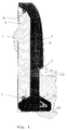
- the crash guards shown in FIGS. 1 and 2 according to the first and second preferred exemplary embodiment of the invention which are arranged at the angle between a wall 1 and a floor 2 of a factory room, have a core 3 which is cast from concrete, optionally mixed with suitable fillers and an anchored to this jacket part 4 made of stainless steel or the like, which on the one hand forms a resilient surface of the impact protection and on the other hand serves as part of the formwork for casting the concrete core 3.
- the concrete core 3 has a foot part 5, which stands on the raw or finished floor 2a, 2b of the factory space or can be fastened to it, as will be explained in more detail below.
- the impact protection has on its side facing the wall 1 or in the interior of the concrete core 3 optionally a filler 6 made of a hard foam such as polystyrene foam, which can also serve as part of the formwork for casting the concrete core 3 and reduces the weight of the impact protection.
- a filler 6 made of a hard foam such as polystyrene foam, which can also serve as part of the formwork for casting the concrete core 3 and reduces the weight of the impact protection.
- the impact protection constructed in this way can, as will be explained with reference to FIGS. 4A to 6, be prefabricated in modules as a finished part, which is then installed at the construction site.
- the jacket part 4 made as a profiled sheet has a convex shape, i.e. it is arched into the factory area when the ram protection is installed.
- the casing part 4 is angled inwards or outwards twice, the angled ends 7, 8 being formed as undercuts which the casing part 4 when the concrete core 3 is poured on Anchor the concrete core 3.
- a strip 9 of a soft foam such as neoprene is inserted or glued in the longitudinal extension of the ram protection, the relative movements and / or relative expansions between the Shells part 4 and the concrete core 3 compensates and serves for insulation purposes.
- the foot part 5 of the concrete core 3 is of anchor-shaped cross section according to FIG. 1 and can be stiffened with a correspondingly shaped steel reinforcement 10 which extends up to the upper end of the impact protection, i.e. extends through the concrete core 3 until adjacent to the upper end 8 of the casing part 4.
- the foot part 5 of the concrete core 3 can also have a different cross section, for example a rectangular cross section.
- the filling part 6 is at its upper or lower ends with respect to the impact protection provided with suitably shaped recesses 11 which extend in the longitudinal direction of the impact protection and which fill with concrete when the concrete core 3 is poured and thus anchor the filling part 6 on the concrete core 3.
- the filler 6 can also be omitted, so that the ram protection has a solid concrete core 3.
- FIG 1 and 2 also show two different installation options for the crash guards according to the invention.
- the ram protection is placed on the wall 1 on the raw floor 2a of the factory space and then the finished floor 2b is poured, the anchor part 5 of the concrete core 3 anchoring the ramming protection.
- a layer 12 of rubber or foam rubber is then applied to the hardened finished floor 2b, which also covers the corner region 13 formed between the hardened finished floor 2b and a side surface of the concrete core 3 and extends to the lower end 7 of the casing part 4, on which it fits tightly. This prevents moisture from penetrating into the joint between the concrete core 3 and the prefabricated floor 2b when the impact protection is installed, which could damage the prefabricated floor 2b or the impact protection by capillary action of this joint and / or by changing the ambient temperature.
- the crash protection shown in FIG. 2 is fastened to the finished floor 2b.
- a plurality of wall anchors 14 are attached at a suitable distance from one another, for example by pouring, in the finished floor 2b or in the raw floor 2a, which protrude upward from the finished floor 2b with a predetermined length.
- the wall anchors 14 reach through recesses 15 provided in the concrete core 3 and the filling part 6, which are introduced during the prefabrication of the impact protection, for example by inserting appropriate cores.
- the upper ends of the wall anchors 14 are firmly connected to the ram protection by means of suitable connecting devices, for example by gluing.
- These connecting devices can then be formed by adhesive cartridges 16, which are arranged in the ends of the cutouts 15 during the prefabrication of the ram guards.
- Such an adhesive cartridge 16 consists, for example, of a plastic bag, which is preferably filled with an adhesive based on synthetic resin and is pierced by the corresponding wall anchor 14 when the ram protection device is placed on the finished floor 2b, so that the adhesive is distributed and cures.
- the prefabricated floor 2b and a lower section of the impact protection are also provided with a layer 12 of rubber or foam rubber in this installation option.
- a seal 17 is introduced, which extends along the wall 1 joint between the crash protection and wall 1 closes.
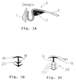
- a sealing profile 18 made of an elastic plastic is preferably used as the seal 17, as shown in FIGS. 3B and 3C, but the joint could also be grouted in a permanently elastic manner.
- the sealing profile 18 has a T-shaped upper sealing section 19 and a lower sealing and Holding section 20 on.
- the upper sealing section 19 has two sealing lips 19.1, one of which, in the installed state of the sealing profile 18 according to FIG. 2, lies sealingly against the upper end 8 of the casing part 4 and the other against the wall 1.
- the lower sealing and holding section 20 has a plurality of herringbone-like sealing and holding lips 20.1, which are set in the installation direction of the sealing profile 18 in order to clamp the sealing profile 18 by elastically spreading the sealing and holding lips 20.1 in the joint and releasing the To prevent sealing profile 18.
- the sealing and holding lips 20.1 also lie in a sealed manner in the installed state of the sealing profile 18 at the upper end 8 of the casing part 4 or on the wall 1.
- the clamping effect described can, as shown in FIG. 3C, be further reinforced by designing the lower sealing and holding section 20 as a hollow profile. Furthermore, the clamping of the sealing profile 18 in the joint can be further improved in that the upper end 8 of the casing part 4 is angled so that in the installed state of the impact protection the joint between the impact protection and the wall 1 tapers upwards.
- FIG. 3A shows an advantageous embodiment of the upper end 8 of the casing part 4, the end 8 for receiving the sealing profile 18 being of hook-shaped cross section.
- the joint for receiving the sealing profile 18 tapers.
- the end face of the upper end 8 of the jacket part 4 facing the wall 1 in the installed state of the impact protection is on the wall 1 or is at a small distance from the wall 1, so that the sealing lips 19.1 of the upper sealing section 19 of the sealing profile 18 can rest against the wall 1 or the outer surface of the casing part 4.
- the jacket part 4 consists of several sections 4.1 to 4.3, for example joined by welding, the joined ends of which are cut or bent in such a way that an inner corner or an outer corner is made of metal, which, as with reference to FIG 1 and 2 described, serves as part of the formwork when casting the concrete core 3 and forms a smooth and resistant outer surface in the prefabricated state of the impact protection module.
- 6 shows a double profile module of the crash protection according to the invention, which delimits a sandwich wall 1 downwards or carries it by means of a receiving groove 21 and has a jacket part 4 (4.4 and 4.5) on both sides of the wall 1.
- the receiving groove 21, like the cutouts 15 for fastening the ram protection, can be produced by inserting removable cores when the concrete core 3 is poured. Furthermore, in combination with the inner and outer corner modules shown in FIGS. 4A to 5B, corner modules with a double profile, ie with two opposite jacket parts, can be produced, so that the Walls of factory rooms built in sandwich construction can be completely provided with a ram protection.
- FIG. 7 shows the completion of the impact protection according to the invention using the example of the closing situation on a door frame 22, a bollard 23 made of stainless steel and / or concrete being provided on both sides of the door frame 22 in order to prevent damage to the door frame 22.
- a first variant is shown, according to which the jacket part 4 of the impact protection module consists of three sections 4.6, 4.7 and 4.8, while the lower part of FIG. 7 shows a second variant, according to which the jacket part 4 of the impact protection module consists of two sections 4.6 and 4.7.
- the sections 4.6 of the casing parts 4 of these crash protection modules correspond in cross section to the casing parts 4 described with reference to FIGS. 1 and 2.
- the sections 4.7 and 4.8 are formed by flat metal or stainless steel plates which are welded to the sections 4.6, wherein the flat sections 4.7 form an angle ⁇ of preferably 40 ° with the wall 1 and the flat section 4.8 of the first variant extends in a substantially perpendicular direction to the wall 1.
- the ram guards described with reference to FIGS. 1 and 2 have in common that they can be brought to the construction site as prefabricated finished parts, where they are then installed. Depending on the on-site requirements, it may be necessary to pour concrete into the ram protection at the construction site. This can be particularly appropriate if the walls are uneven, so that smaller tolerances have to be compensated for at the construction site.
- the existing factory layout can also have areas that require a special adaptation of the impact protection to the on-site conditions.
- the ramming protection according to the third exemplary embodiment is arranged at the angle between the wall 1 and the floor 2 of the factory space and in the finished state has a core 3 cast from concrete and a jacket part 4 anchored to it Metal, preferably stainless steel.
- the jacket part 4 of the third exemplary embodiment shown individually in FIG.
- jacket part 10 differs from the jacket part described above essentially in that it is provided on its upper end face 24 with a preferably circular opening 25 which serves to fill the ramming protection with concrete and then with a cover made of stainless steel (not shown) is welded closed or closed with a plastic cover (not shown) which is flush with the upper end face 24.
- the metal forming the jacket part 4 is not continuously curved as in the case of FIGS. 1 and 2, but rather only over a relatively short area, so that a curved area 26 with a radius of curvature of approximately 60 adjoins the essentially flat upper end face 24 mm connects, to which a lateral end face 27 connects, which is also essentially flat.
- anchoring plates 28 are welded or screwed to the jacket part 4 directly adjacent to the upper end 8 of the jacket part 4 or directly at the angled lower end 7 of the jacket part 4.
- the ends of the anchoring plates 28 protruding into the concrete core 3 are angled in a zigzag shape in order to ensure a form-fitting fixing of the casing part 4 on the concrete core 3.
- the anchoring plates 28 are approximately 20 mm wide strips of sheet metal, preferably made of stainless steel, which are arranged in succession in the longitudinal direction of the impact protection at a distance of approximately 500 mm.
- a separating mat 30 is first made of foam, for example, which is about 5 mm thick and serves to separate wall 1 and impact protection.
- the separating mat 30 is preferably glued to the wall 1 with a suitable adhesive.
- a Z-shaped profile 31 is screwed onto the wall 1 provided with the separating mat 30, which runs essentially continuously in the longitudinal direction of the impact protection and serves to fasten the upper end 8 of the casing part 4 to the wall 1.
- the Z-shaped profile 31 is angled in such a way that it protrudes like a hook from the wall 1, at a height which essentially corresponds to the height of the finished crash protection.
- the simply angled downward in the drawing upper end 8 of the jacket part 4 can thus be hooked into the upwardly open profile 31, wherein an end section of the profile 31 extending parallel to the wall 1 is spaced apart from the wall 1 by an amount which is greater than the sheet thickness of the jacket part 4, so that smaller tolerances on site can be compensated for.
- spacers 32 are welded or screwed to the simply angled lower end 7 of the jacket part 4 in the longitudinal extension direction of the jacket part 4 at a suitable distance (for example every 500 mm) and, if necessary, screwed to the wall 1 to compensate for tolerances, so that the partition mat 30 is located between the spacer 32 or the spacer 33 and the wall 1.
- the spacer 32 is a sheet metal strip, preferably made of stainless steel, which is approximately 25 mm wide and bent in an L-shape, the end of the spacer 32 connected to the angled lower end 7 of the jacket part 4 being bent again by approximately 15 °, so that it can lie flush against the lower end 7 of the jacket part 4.
- the casing part 4 is fastened to the wall 1 in such a way that the lower end 7 of the casing part 4 is spaced from the floor 2 (in the case shown a sloping concrete floor) by about 70 to 80 mm and the lateral end face 27 is essentially parallel to the wall 1 extends.
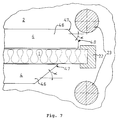
- a device 50 consists of three rectangular metal profiles 51 welded into a right-angled triangle, of which the metal profile 51 forming the hypotenuse extends beyond the triangle and is provided with an adjusting foot 52 at its end.
- the leveling foot 52 consists of a threaded bolt 53 which is welded to the metal profile 51 Threaded bushing 54 is screwed in and, at its end facing the jacket part 4, has a section 55 which is enlarged in diameter compared to the diameter of the threaded bolt 53 and which forms a positioning surface which comes into engagement with the upper end face 24 of the jacket part 4.
- the metal profiles 51 forming the right angle are provided on their end faces facing the bottom 2 or the wall 1, each with two perforated tabs 56, which serve to fasten the device 50 to the bottom 2 or with one flush with the lateral end face 27 of the Shell part 4 adjacent formwork board 57 are screwed from a waterproof plywood.
- the formwork board 57 is screwed below the lower end 7 of the casing part 4 to a plastic board 58 made of, for example, Nierolen® and extending along the casing part 4, on the lower edge of which a sealing lip 59 made of soft PVC is attached, which is bent in the switched-on state of the jacket part 4 in the direction of the wall 1 in order to prevent concrete from flowing out.
- a gasket 60 made of foam rubber is inserted between the formwork board 57, which ends flush in the direction of the floor 2 with the vertical metal profile 51, and the floor 2, which additionally seals the formwork to the outside.
- the seal 60 which is circular in cross section in the unloaded state, has a diameter which is at least twice as large as the thickness of the lower tabs 56, which space the device 50 from the base 2.
- the device 50 fastened to the floor 2 thus seals the ramming protection from the outside via the sealing lip 59 and the seal 60 and holds the casing part 4 in its predetermined position, the formwork board 57 being the parallel position of the lateral end face 27 of the jacket part 4 with respect to the wall 1, while the adjustable foot 52 prevents that the upper end face 24 of the casing part 4 can move upwards.
- the impact protection is filled with concrete 3 through the openings 25 in the upper end face 24 of the casing part 4.
- the concrete used preferably B10 - B15
- the concrete used is mixed with a retarder and a foaming agent.
- the impact protection complete i.e. Filled with concrete up to close to the inside of the casing part 4 facing away from the upper end face 24, and the concrete was able to set for about 24 hours
- the ram protection is switched off, for which purpose the device 50 consisting of parts 51 to 60 is removed from the ramming protection.
- the jacket part 4 is now reliably fixed via the angled ends 7 and 8 acting as undercuts and the anchoring plates 28 on the concrete core 3 and forms the resilient surface of the impact protection without this being able to separate from the concrete core 3.
- the sloping concrete floor 2 can be provided with a plastic floor, which adjoins the lower end 7 of the casing part 4 with a fillet 61 (shown in broken lines in FIG. 8).
- a fillet 61 shown in broken lines in FIG. 8
- the part of the separating mat 30 projecting upward above the ram protection is cut off and the gap 34 extending between the upper end 8 of the casing part 4 and the wall 1 and extending up to the Z-shaped profile 31 groomed.
- a band or cord 35 made of a suitable fabric is first inserted into the base of the joint 34 formed by the Z-shaped profile 31, which extends along the ram protection.
- the joint 34 is then finished with silicone 36.
- the cord 35 is provided so that the silicone 36 through Pulling out the cord 35 can be easily removed from the joint 34 if the joint 34 is to be newly grouted, for example for hygiene reasons.
- the openings 25 in the upper end face 24 of the casing part 4 are welded closed by means of suitably shaped lids (not shown) and the weld seams are treated in such a way that the upper end face 24 is smooth and flat.
- the ram protection according to the third exemplary embodiment of the invention is particularly suitable for “made-to-measure” items, for example on uneven walls, since smaller on-site tolerances can be compensated for via the Z-shaped profile 31 or the spacers 32 and spacers 33, the ramming protection via the jacket part 4 forms a flat, resilient surface which extends essentially parallel to the wall 1.
- the jacket part 4 serves as part of the formwork, so that the manufacture of the impact protection is simplified.
- sanitary pipes 37 preferably made of stainless steel, can be welded to the jacket part 4, thereby making sanitary installations and / or electrical installations in the ram protection before pouring the ramming protection with concrete.
- This is particularly advantageous if pipes or lines are to be retrofitted with appropriate planning, since pipes and lines can be retrofitted in the impact protection without the walls having to be opened.
- Such internals, which are attached to the casing part 4, can equally be provided in the first to third exemplary embodiments.
- a ram protection is proposed, which can be arranged between a wall 1 and a floor 2 of a factory space, and has a core 3 cast from concrete and an anchored part 4 made of stainless steel or the like.
- this jacket part 4 forms a resilient surface of the impact protection and, on the other hand, serves as part of the formwork for casting the concrete core 3.
- it is characterized by good wear resistance.
Landscapes
- Engineering & Computer Science (AREA)
- Architecture (AREA)
- Civil Engineering (AREA)
- Structural Engineering (AREA)
- Health & Medical Sciences (AREA)
- Epidemiology (AREA)
- Public Health (AREA)
- Building Environments (AREA)
- Forms Removed On Construction Sites Or Auxiliary Members Thereof (AREA)
Applications Claiming Priority (2)
| Application Number | Priority Date | Filing Date | Title |
|---|---|---|---|
| DE4340953A DE4340953C1 (de) | 1993-12-01 | 1993-12-01 | Rammschutz |
| DE4340953 | 1993-12-01 |
Publications (2)
| Publication Number | Publication Date |
|---|---|
| EP0656446A2 true EP0656446A2 (fr) | 1995-06-07 |
| EP0656446A3 EP0656446A3 (fr) | 1996-09-25 |
Family
ID=6503919
Family Applications (1)
| Application Number | Title | Priority Date | Filing Date |
|---|---|---|---|
| EP94118851A Withdrawn EP0656446A3 (fr) | 1993-12-01 | 1994-11-30 | Protection contre les impacts. |
Country Status (2)
| Country | Link |
|---|---|
| EP (1) | EP0656446A3 (fr) |
| DE (1) | DE4340953C1 (fr) |
Cited By (1)
| Publication number | Priority date | Publication date | Assignee | Title |
|---|---|---|---|---|
| EP1571273A1 (fr) * | 2004-03-02 | 2005-09-07 | Schweyer S.A | Dosseret de protection de la base d'un mur ou d'une paroi, et son procédé de fabrication |
Families Citing this family (6)
| Publication number | Priority date | Publication date | Assignee | Title |
|---|---|---|---|---|
| FR2763618A1 (fr) * | 1997-05-26 | 1998-11-27 | Klein Pere Et Fils | Procede de construction d'une banquette de protection et moyens pour la mise en oeuvre du procede |
| ITTO20020211A1 (it) * | 2002-03-12 | 2003-09-12 | Selmat Automotive S R L | Assorbitore di urti per riscontri fissi, in particolare per la realizzazione di barriere di protezione stradale. |
| BE1017613A6 (nl) | 2007-05-23 | 2009-02-03 | Bumacop Nv | Beschermplint. |
| WO2019219900A1 (fr) | 2018-05-18 | 2019-11-21 | Polysto | Perfectionnement apporté à des éléments de revêtement mural et de bardage |
| US11485094B2 (en) | 2018-05-18 | 2022-11-01 | Polysto | Process for the production of an article for the cladding of floors or walls |
| BE1029197B1 (nl) | 2021-03-15 | 2022-10-17 | Alva Tech | Werkwijze voor het vervaardigen van een bouwelement, een bijbehorend bouwelement |
Family Cites Families (6)
| Publication number | Priority date | Publication date | Assignee | Title |
|---|---|---|---|---|
| US1950634A (en) * | 1931-10-31 | 1934-03-13 | Milcor Steel Company | Metallic base-board |
| US2178501A (en) * | 1939-02-15 | 1939-10-31 | Anthony R Staneampiano | Metal base |
| CH344205A (de) * | 1954-07-26 | 1960-01-31 | Braun Pebra Gmbh | Sockelleiste und Verwendung dieser Sockelleiste zur Herstellung eines Fussbodensockels |
| DE8617361U1 (de) * | 1986-06-28 | 1988-06-01 | Bayerische Motoren Werke AG, 8000 München | Vorrichtung zum Schützen von Kanten von Trägern, Gestellen ö.ä. vor mechanischer Beschädigung |
| SE468822B (sv) * | 1991-03-14 | 1993-03-22 | Postverket Postfastigheter | Anordning foer skydd av vaeggar och maskiner mot paakoerning av lastbaerare |
| EP0604527A1 (fr) * | 1991-09-18 | 1994-07-06 | MORGAN, Philip, Nigel | Plancher comportant un element de constitution d'un bord |
-
1993
- 1993-12-01 DE DE4340953A patent/DE4340953C1/de not_active Expired - Fee Related
-
1994
- 1994-11-30 EP EP94118851A patent/EP0656446A3/fr not_active Withdrawn
Cited By (2)
| Publication number | Priority date | Publication date | Assignee | Title |
|---|---|---|---|---|
| EP1571273A1 (fr) * | 2004-03-02 | 2005-09-07 | Schweyer S.A | Dosseret de protection de la base d'un mur ou d'une paroi, et son procédé de fabrication |
| FR2867209A1 (fr) * | 2004-03-02 | 2005-09-09 | Serge Villain | Dosseret de protection de la base d'un mur et son procede de fabrication |
Also Published As
| Publication number | Publication date |
|---|---|
| EP0656446A3 (fr) | 1996-09-25 |
| DE4340953C1 (de) | 1995-04-06 |
Similar Documents
| Publication | Publication Date | Title |
|---|---|---|
| DE69403902T2 (de) | Gussbetonwände | |
| DE69829489T2 (de) | Vorgeformte Abdeckleiste, Schalungssystem und Trennwandausbildungsverfahren | |
| DE2226889A1 (de) | Bausystem, insbesondere zur Ernch tung von Gebäuden, Container und Fahr zeugaufbauten | |
| EP0546296A1 (fr) | Dispositif de perfectionnement d'un joint de dilatation dans un sol couvert par des carreaux de céramique | |
| EP0563436A1 (fr) | Bâtiment transportable et sa méthode de construction | |
| DE69400949T2 (de) | Verfahren zum Errichten eines Silos bzw. Tanks mit Auskleidung sowie Wandplatte zum Errichten eines Silos bzw. Tanks und Verfahren zur Herstellung einer solchen Wandplatte | |
| EP2060377A2 (fr) | Montage de cuve et procédé d'établissement d'un montage de cuve | |
| EP0465935A1 (fr) | Module de bâtiment | |
| EP0656446A2 (fr) | Protection contre les impacts | |
| DE10262101B4 (de) | Dämmstoffplatte | |
| DE68913552T2 (de) | Vorgefertigtes gebäude. | |
| DE60111447T2 (de) | Überlaufsystem mit Überlaufschwelle, insbesondere für vorgefertigte, in den Boden zu versenkende Schwimmbecken und Verfahren zur dessen Konstruktion | |
| DE69721174T2 (de) | Dichtungsvorrichtung für Schwimmbadauskleidung | |
| DE2115250C3 (de) | Geschoßhohes Wandelement | |
| DE29802829U1 (de) | Überlaufrinne für Schwimmbecken | |
| DE4319632A1 (de) | Auflagerelement für Bauelemente | |
| DE2451520C2 (de) | Lärmschutzelement | |
| DE3215303C2 (de) | Verfahren zur Herstellung eines Rolladenkastens | |
| EP0106297A2 (fr) | Elément de construction pour la fabrication de murs en béton et mur de bâtiment fabriqué avec celui-ci | |
| DE2336482A1 (de) | Raumzelle fuer gebaeude | |
| DE3203980C2 (de) | Unterführungsbauwerk sowie Verfahren zu seiner Herstellung | |
| DE19740804A1 (de) | Balkon | |
| DE2912131C2 (de) | Garage | |
| DE1264031B (de) | Im Erdboden eingebautes Schwimmbecken aus Bauteilen, die mittels Flanschen verschraubt sind | |
| EP1736605A2 (fr) | Chassis de balcon, balcon et procédé de réalisation d'un balcon préfabriqué |
Legal Events
| Date | Code | Title | Description |
|---|---|---|---|
| PUAI | Public reference made under article 153(3) epc to a published international application that has entered the european phase |
Free format text: ORIGINAL CODE: 0009012 |
|
| AK | Designated contracting states |
Kind code of ref document: A2 Designated state(s): AT BE CH DE FR IT LI NL |
|
| RBV | Designated contracting states (corrected) |
Designated state(s): AT BE CH DE FR IT LI NL |
|
| PUAL | Search report despatched |
Free format text: ORIGINAL CODE: 0009013 |
|
| AK | Designated contracting states |
Kind code of ref document: A3 Designated state(s): AT BE CH DE FR IT LI NL |
|
| STAA | Information on the status of an ep patent application or granted ep patent |
Free format text: STATUS: THE APPLICATION IS DEEMED TO BE WITHDRAWN |
|
| 18D | Application deemed to be withdrawn |
Effective date: 19970531 |