EP0656457A2 - Sicherheitstür - Google Patents
Sicherheitstür Download PDFInfo
- Publication number
- EP0656457A2 EP0656457A2 EP94308991A EP94308991A EP0656457A2 EP 0656457 A2 EP0656457 A2 EP 0656457A2 EP 94308991 A EP94308991 A EP 94308991A EP 94308991 A EP94308991 A EP 94308991A EP 0656457 A2 EP0656457 A2 EP 0656457A2
- Authority
- EP
- European Patent Office
- Prior art keywords
- door
- rails
- panel members
- rail
- members
- Prior art date
- Legal status (The legal status is an assumption and is not a legal conclusion. Google has not performed a legal analysis and makes no representation as to the accuracy of the status listed.)
- Withdrawn
Links
- 230000015572 biosynthetic process Effects 0.000 claims abstract description 31
- 238000005755 formation reaction Methods 0.000 claims abstract description 31
- 229910052751 metal Inorganic materials 0.000 claims abstract description 10
- 239000002184 metal Substances 0.000 claims abstract description 10
- 230000007246 mechanism Effects 0.000 claims abstract description 8
- 239000000463 material Substances 0.000 claims description 11
- 238000001125 extrusion Methods 0.000 claims description 6
- 239000006261 foam material Substances 0.000 claims description 6
- 230000000295 complement effect Effects 0.000 claims description 5
- 238000010348 incorporation Methods 0.000 claims 1
- 125000006850 spacer group Chemical group 0.000 description 10
- 238000010276 construction Methods 0.000 description 9
- 238000000034 method Methods 0.000 description 5
- 239000006260 foam Substances 0.000 description 4
- 239000011800 void material Substances 0.000 description 4
- 229920001944 Plastisol Polymers 0.000 description 2
- 239000000853 adhesive Substances 0.000 description 2
- 230000001070 adhesive effect Effects 0.000 description 2
- 239000011490 mineral wool Substances 0.000 description 2
- 229920003023 plastic Polymers 0.000 description 2
- 239000004033 plastic Substances 0.000 description 2
- 239000004999 plastisol Substances 0.000 description 2
- 238000000926 separation method Methods 0.000 description 2
- 229920005830 Polyurethane Foam Polymers 0.000 description 1
- 229910000831 Steel Inorganic materials 0.000 description 1
- 208000027418 Wounds and injury Diseases 0.000 description 1
- 239000004411 aluminium Substances 0.000 description 1
- 229910052782 aluminium Inorganic materials 0.000 description 1
- XAGFODPZIPBFFR-UHFFFAOYSA-N aluminium Chemical compound [Al] XAGFODPZIPBFFR-UHFFFAOYSA-N 0.000 description 1
- 230000006378 damage Effects 0.000 description 1
- 239000000428 dust Substances 0.000 description 1
- 239000002657 fibrous material Substances 0.000 description 1
- 208000014674 injury Diseases 0.000 description 1
- 230000014759 maintenance of location Effects 0.000 description 1
- 239000013521 mastic Substances 0.000 description 1
- 239000000203 mixture Substances 0.000 description 1
- 229920002635 polyurethane Polymers 0.000 description 1
- 239000004814 polyurethane Substances 0.000 description 1
- 239000011496 polyurethane foam Substances 0.000 description 1
- 239000010959 steel Substances 0.000 description 1
- 239000000725 suspension Substances 0.000 description 1
Images


Classifications
-
- E—FIXED CONSTRUCTIONS
- E06—DOORS, WINDOWS, SHUTTERS, OR ROLLER BLINDS IN GENERAL; LADDERS
- E06B—FIXED OR MOVABLE CLOSURES FOR OPENINGS IN BUILDINGS, VEHICLES, FENCES OR LIKE ENCLOSURES IN GENERAL, e.g. DOORS, WINDOWS, BLINDS, GATES
- E06B3/00—Window sashes, door leaves, or like elements for closing wall or like openings; Layout of fixed or moving closures, e.g. windows in wall or like openings; Features of rigidly-mounted outer frames relating to the mounting of wing frames
- E06B3/92—Doors or windows extensible when set in position
-
- E—FIXED CONSTRUCTIONS
- E06—DOORS, WINDOWS, SHUTTERS, OR ROLLER BLINDS IN GENERAL; LADDERS
- E06B—FIXED OR MOVABLE CLOSURES FOR OPENINGS IN BUILDINGS, VEHICLES, FENCES OR LIKE ENCLOSURES IN GENERAL, e.g. DOORS, WINDOWS, BLINDS, GATES
- E06B3/00—Window sashes, door leaves, or like elements for closing wall or like openings; Layout of fixed or moving closures, e.g. windows in wall or like openings; Features of rigidly-mounted outer frames relating to the mounting of wing frames
- E06B3/70—Door leaves
- E06B3/82—Flush doors, i.e. with completely flat surface
- E06B3/822—Flush doors, i.e. with completely flat surface with an internal foursided frame
Definitions
- the present invention relates to doors and in particular to security doors of the type which may be fitted in secure premises. Such doors may also find use as domestic front entry doors and in community housing projects where added security is desired.
- a security door is known from granted European Patent No. 0 392 700 B in which the leaf is constructed from a minor sheet metal tray and a major sheet metal tray, each of which is formed with lip portions receivable in slotted internal frame members.
- the respective trays are effectively bent metal sheets and the internal frame members are elongate metal extrusions.
- the cavity inside the assembled door may be filled under pressure with a curable foam material.
- wrap-around construction of the major tray may also mean that it is not possible for a would-be customer to obtain doors of sufficient width, since the returned portions account for between 10 and 15cm of the metal sheet from which the door is constructed. Many sheet materials are supplied in standard widths and it may therefore be the case that a door cannot be made to the prior art design in the material of choice.
- the invention is a door comprising first and second sheet metal door panel members, a pair of side rails and a top and bottom rail, each of said door panel members having overturned lip formations around each of its edges, the free ends of said overturned lip formations overlying their respective door panel members and being spaced therefrom, and each of said rails having a pair of parallel longitudinal grooves along at least one common face thereof dimensioned to receive the overturned lip formations of corresponding edges of each of said first and second door panel members.
- a door in accordance with the invention has none of its constructional features exposed on its faces. This offers the advantage that, when such a door is in the closed condition, its construction is hidden by the surrounding door frame and is therefore not vulnerable to attack .
- At least one of the pairs of oppositely-disposed rails includes extension means.
- extension means This not only allows the ends of a rail to be urged into positive engagement with the ends of its neighbours for imparting improved rigidity to the door, but also means that one size of rail can be used to make doors of various dimensions. In practice, it will usually be the top and bottom rails which are provided with extension means since there tends to be greater standardisation in door heights than there is in door widths. Nevertheless, either or both pairs of rails may include extension means.
- the extension means comprise telescopic portions built into the rails. The telescopic portion is lockable in its extended condition to maintain the desired degree of separation between the rail ends.
- the extension means may be an insert portion. Insert portions of different lengths can be employed with standard-sized rails to achieve a range of different sizes.
- the insert portions and rails may have complementary bevelled formations to assist in urging the rail ends into their respective corners of the door panel members through a wedging action.
- the rail ends are formed with mitres. In combination with rail members having extension means, this enables the rails to extend fully into the corners of the door. This design therefore has particularly strong corners.
- adjacent rail ends may be formed with bevelled portions of complementary angles other than 45°, to suit particular application requirements.
- the rail material is an elongate metal extrusion. Between the parallel longitudinal grooves formed along at least one face thereof for receipt of the overturned lip formations of the door panel members, the rail may have a longitudinal recess.
- the rail has the longitudinal grooves formed along two opposite faces and a longitudinal recess of a different depth formed between each pair of parallel grooves.
- one of the recesses may be of a depth suitable to receive hinges on which the door would be suspended, whilst the recess along the opposite face may be dimensioned to receive a multi-point locking mechanism as known in the art.
- Such a dual-faced rail offers the advantage that only a single extrusion needs to be stocked by the door manufacturer to accommodate a variety of ironmongery.
- the elongate rail members can be formed from a suitable plastics material.
- the edge portions may be fitted with a capping member to cover the exposed rails. This not only helps to prevent the ingress of dust and dirt, but also offers protection from injury in the event of a collision with the door panel member edges.
- the capping member may be of a contrasting colour to assist in identifying the escape passage during an emergency.
- the capping member may be adapted to engage with the parallel grooves of the rail members or with the door panel overturned lip formations.
- the capping member may contribute to the retention of the door panel overturned lip formations within the grooves by being an interference fit therewith.
- the overturned lip formations are continuous around the entire periphery of the respective door panel members and the cavity between the door panel members is filled with a curable foam material which may be injected under pressure.
- the foam secures the rails and door panel members in place relative to each other and improves the structural integrity of the door.
- Keying projections may be provided on the rails to assist in this process.
- the keying function may be fulfilled by the second pair of longitudinal grooves and their associated recess.
- the cavity between the door panel members may be packed with an infill of a non-curable material, for example, a fibrous fireproof material such as Rockwool (Registered Trade Mark).
- a non-curable material for example, a fibrous fireproof material such as Rockwool (Registered Trade Mark).
- Rockwool Registered Trade Mark
- an alternative method must be used for urging the internal framework of the door into firm engagement with the overturned lip formations of the panel members.
- One method of doing this is to use one or more jacking mechanisms extending across the interior of the door cavity, the slabs of infill material being positioned in the spaces between the top and bottom rails of the door and respective jacking mechanisms.
- the jacking mechanism comprises a jacking rod accommodated in the centre void of spacer means, for example formed from lengths of the same material used to form the rail members.
- An intermediate portion of the jacking rod is secured against rotation relative to the spacer means and each of its ends is provided with a screw thread which is adapted to receive a cooperating jacking member.
- the side rails are caused to move away from each other and are thereby urged into firm engagement with the overturned lip formations of the door panel members.
- one end of the jacking rod may be fixed to one of the side rail members so that only one jacking member is necessary for each jacking rod.
- the door panel members are preferably affixed, for example by adhesives, to intermediate spacers.
- the spacers may also serve as housings for the jacking rods.
- Intermediate bracing of this type serves to minimise inward and outward flexure (so-called "panting") of the door panels and helps to improve overall structural integrity of the door.
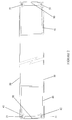
- a door constructed in accordance with the invention comprises a pair of "Plastisol” (Registered Trade Mark) door panel members 10, 20, and rail members 30, 40 of extruded aluminium arranged to be disposed between the panel members.
- the rail members have their ends 30a, 40a cut at complementary angles to facilitate formation of rigid corner joints for maximum strength.
- the panels 10, 20 are shown with overturned lip formations 11, 21, respectively, around their peripheries.
- Each rail member has a pair of longitudinally-extending parallel grooves along at least one face, which grooves are oriented to receive the overturned lip formations of a respective door panel.
- Polyurethane foam 60 fills the void between the panel members in the finished door assembly and secures them against inward and outward flexure, or "panting”.
- a capping member 50 is shown overlying one of the rail members.
- first panel member 10 Assembly of the door is accomplished by laying first panel member 10 horizontally to form a shallow tray.
- rail members are placed on the tray, corresponding to the two side rails and a top and bottom rail of the finished door.
- the second panel member 20 is then placed on top of the rail members, which are each slid outwardly until the overturned lip formations of the respective panel members are received in the grooves of the rail members.
- the operation of sliding the rail members into engagement with the overturned lip formations of the panel members may be performed by a variety of methods, depending on the particular configuration of the rail members used. If rail members having bevelled ends are used, as in the present example, it is necessary to use extension means to expand the rails into the corners of the door panel members.
- suitable expansion means is described below with reference to Figure 3.
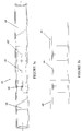
- FIG 2 is shown a cross-section through the door of Figure 1 after assembly.
- the foam filling 60 has been omitted for clarity.
- This view shows a pair of opposed rails 40, 41b with a pair of parallel grooves 42 formed on one face thereof in which are received the overturned lip formations 11, 21 of the respective panel members 10, 20.
- capping members 50 are formed with returned edge portions 51 which are also received in the grooves of the rail members. The overturned lip formations of the panel members and the returned edge portions of the capping members together form an interference fit in respective grooves of the rail members.
- Figures 3(a) and 3(b) are cross-sectional views through an edge of a door constructed in accordance with the present invention, showing a rail member 40 with expansion means in the form of a telescopic portion 43 inserted between its two ends 48 and 49.
- the telescopic portion includes an inner sleeve 44 which is permanently secured through fixing means 45 to a first end 48 of the rail member.
- the inner sleeve is slidably received in the other end 49 of rail member 40 and is releasably securable thereto in a selected position by means of releasable fastening means 46.
- a door is constructed from rail members having mitred corners.
- the side rail members of the door are non-extensible and the top and bottom rail members are formed with telescopic portions in accordance with Figure 3.
- the four rail members are placed on the first panel member 10 with the telescopic portions in the unextended condition.
- the side rail members are first manoeuvred into engagement with the overturned lip portions of the panel members.
- the top and bottom rail members are positioned in engagement with the overturned lip portions of the panel members and their telescopic portions are extended to bring the mitred ends of all four rails into contact.
- a curable foam material such as polyurethane is injected into the cavity between the panel members through a hole or holes provided in the rail members. After curing, the door is released from the press. It is necessary to apply external pressure to the door panels during this operation in order to prevent undesirable bulging in the finished article. In practice, it is possible to stack a number of doors together and to fill each of them with foam for treatment in a single curing step.
- Figure 4 shows a particularly preferred form of the rail member extrusion 30.
- This rail member has two opposed faces of dissimilar section, each of which is provided with a pair of longitudinally-extending parallel grooves 32. Between each of the pairs of grooves 32 is formed a longitudinally-extending recess 33, 34.
- One of the recesses 33 is relatively shallow and is configured to receive hinges for suspension of the door.
- the recess 34 along the opposite face of the rail is relatively narrow and much deeper in comparison to recess 33. This deeper recess is suitable for accommodating a multi-point locking mechanism. Such locking mechanisms are well known in the art and need not be described in detail here.
- Upstanding projections 35, 36, or 35, 37 on the face of the rail member facing inwardly from the door periphery may assist in keying the foam material to the structural members of the door.
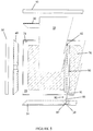
- FIG. 5 there is shown an exploded view of another embodiment of door constructed in accordance with the invention.
- like reference numerals are used to denote components and features in common with the first embodiment described above in relation to Figures 1 to 4.
- the Figure 5 embodiment differs from the first embodiment in that it uses a dry infill 70 of fibrous material such as Rockwool (Registered Trade Mark).
- jacking devices 80 are provided for urging the side rail members 30, 31 into firm engagement with the overturned lip formations 21 of the respective door panel members 10, 20.
- the end rail members 40, 41 (only one shown) are unmodified from the arrangement used in the first embodiment and will not be described further.
- At least one intermediate spacer member 90 is inserted across the door panel 20, substantially perpendicular to the long edges of the door.
- the intermediate spacer member 90 is formed from a length of the same extrusion used to make the side and end rail members 30, 31, 40, 41.
- a jacking rod 81 is inserted into the centre void of the spacer member 90 and protrudes at one end 82 into a slot (38, see Figure 6) in the side rail member 30.
- the jacking rod 81 is secured against rotation and is provided with an external screw thread onto which a jacking member 85 is threadedly engaged.
- Jacking member 85 is shown as having a threaded bore 86 for engagement on the externally threaded jacking rod 81 and has a free end 87 adapted to be engageable by the blade of a screwdriver or similar tool. Between the threaded bore 86 and the free end 87, the jacking member 85 is provided with a shoulder 88 which acts as the thrust surface during the jacking procedure. A standard washer 89 may be interposed between the side rail member 31 and the shoulder 88 of the jacking member 85.
- the free end 87 of the jacking member 85 is accessible through a pair of aligned holes 39 provided in the edge of the side rail 31.
- the side rail member 31 can be caused to move away from side rail 30 in such a way that the respective side rails are urged into firm engagement with the overturned lip formations 11, 21 of the door panel members 10, 20.
- access holes 39 and jacking member free ends 86 are concealed by capping member 50.
- the door panel members 10, 20 may be glued to the intermediate spacer 90 to brace them against inward and outward flexure. This is why it is convenient for the spacers 90 to be formed from a length of the same material as used elsewhere in the door construction for the top, bottom and side rails, since the rails determine the separation between the door panel members.
- the jacking rods 81 may be threaded at both ends, each of which receives a jacking member 85. In such an arrangement, the jacking rods 81 may be secured against rotation by affixing them to the spacers 90.
- a temporary pulling arrangement is required to slide each rail into engagement with the respective overturned lip formations.
- This may comprise, for example, an arrangement of threaded bolts engaged in threaded holes provided through the external groove-bearing faces of the rail members.
- rail members are formed with complementary angled corners
- butted rail members need to be permanently secured to the panel member overturned lip formations, otherwise there is a danger that they will slide out of position between the panel members.
- This permanent attachment may be effected by the foam filling, as discussed above.
- the rail and panel members may be fixed to each other using a suitable adhesive or mastic composition.
Landscapes
- Engineering & Computer Science (AREA)
- Civil Engineering (AREA)
- Structural Engineering (AREA)
- Securing Of Glass Panes Or The Like (AREA)
Applications Claiming Priority (2)
| Application Number | Priority Date | Filing Date | Title |
|---|---|---|---|
| GB9324831 | 1993-12-03 | ||
| GB9324831A GB2284631A (en) | 1993-12-03 | 1993-12-03 | Security door |
Publications (2)
| Publication Number | Publication Date |
|---|---|
| EP0656457A2 true EP0656457A2 (de) | 1995-06-07 |
| EP0656457A3 EP0656457A3 (de) | 1995-08-30 |
Family
ID=10746089
Family Applications (1)
| Application Number | Title | Priority Date | Filing Date |
|---|---|---|---|
| EP94308991A Withdrawn EP0656457A3 (de) | 1993-12-03 | 1994-12-02 | Sicherheitstür. |
Country Status (2)
| Country | Link |
|---|---|
| EP (1) | EP0656457A3 (de) |
| GB (1) | GB2284631A (de) |
Cited By (1)
| Publication number | Priority date | Publication date | Assignee | Title |
|---|---|---|---|---|
| US8713866B2 (en) | 2012-02-23 | 2014-05-06 | Alain GADOURY | Hinge reinforced frame assembly |
Families Citing this family (1)
| Publication number | Priority date | Publication date | Assignee | Title |
|---|---|---|---|---|
| GB2344882B (en) * | 1998-10-08 | 2001-05-30 | Stoves Plc | A method of manufacturing a door for a domestic appliance |
Family Cites Families (7)
| Publication number | Priority date | Publication date | Assignee | Title |
|---|---|---|---|---|
| US3786609A (en) * | 1972-01-07 | 1974-01-22 | Acorn Prod Co | Cored insulated door |
| US3837134A (en) * | 1973-07-11 | 1974-09-24 | Acorn Building Components Inc | Sheet metal faced slab door |
| CA1086569A (en) * | 1977-12-23 | 1980-09-30 | Bernard C. Governale | Liner for intersecting cross bore and edge bore of foam-filled metal skinned door |
| DE3208313A1 (de) * | 1982-03-08 | 1983-09-15 | Richard 5239 Kirburg Held | Thermisch isoliertes stahltor |
| GB8428655D0 (en) * | 1984-11-13 | 1984-12-19 | Ici Plc | Latching mechanisms |
| DE3801568A1 (de) * | 1987-02-25 | 1989-08-03 | Hoermann Belgie Nv | Tor- oder tuerblattfluegel |
| GB2261460A (en) * | 1991-11-12 | 1993-05-19 | H M Hardware Limited | Door construction |
-
1993
- 1993-12-03 GB GB9324831A patent/GB2284631A/en not_active Withdrawn
-
1994
- 1994-12-02 EP EP94308991A patent/EP0656457A3/de not_active Withdrawn
Cited By (1)
| Publication number | Priority date | Publication date | Assignee | Title |
|---|---|---|---|---|
| US8713866B2 (en) | 2012-02-23 | 2014-05-06 | Alain GADOURY | Hinge reinforced frame assembly |
Also Published As
| Publication number | Publication date |
|---|---|
| EP0656457A3 (de) | 1995-08-30 |
| GB9324831D0 (en) | 1994-01-19 |
| GB2284631A (en) | 1995-06-14 |
Similar Documents
| Publication | Publication Date | Title |
|---|---|---|
| US4677791A (en) | Adjustable gate for doorways | |
| CA2248120C (en) | Modular glazing system | |
| US5845439A (en) | Adjustable door and frame assembly | |
| CA2534089C (en) | Glazing system | |
| US4921033A (en) | Security door system | |
| US4437265A (en) | Safety guard | |
| US4807687A (en) | Security door system | |
| EP1000218A1 (de) | Vorrichtung und verfahren zur sicherung von glasscheiben gegen aufprall | |
| US7624548B2 (en) | Temporary closure | |
| US6866081B1 (en) | Exterior door or window having extruded composite frame | |
| US20070113521A1 (en) | Door Edge Construction | |
| CA2100288A1 (en) | Shutter assembly | |
| CA2153402A1 (en) | Security cabinet | |
| US20160273263A1 (en) | Frame assembly for retaining a screen | |
| US5787660A (en) | Extruded vinyl door jamb assembly | |
| CA2181631A1 (en) | Jamb extension assembly for doors and windows | |
| EP1840313B1 (de) | Tür- und/oder Fensterrahmen mit verstellbarer Breite | |
| EP0656457A2 (de) | Sicherheitstür | |
| US3361189A (en) | Hinge strip anchor | |
| US7392628B2 (en) | Functional shutter | |
| EP1184533A2 (de) | Niedrigenergiefenster | |
| DE9314192U1 (de) | Sicherheitstür | |
| DE4234435A1 (de) | Bausatz zur Bildung von Verglasungsrahmen für Fenster, Lichtbänder o. dgl. | |
| GB2345512A (en) | Doors and door assemblies | |
| EP1387032A1 (de) | Vorichtungssatz zum bedecken und schützen von tür- und fensterrahmen, bis die fenster und türen installiert sind |
Legal Events
| Date | Code | Title | Description |
|---|---|---|---|
| PUAI | Public reference made under article 153(3) epc to a published international application that has entered the european phase |
Free format text: ORIGINAL CODE: 0009012 |
|
| AK | Designated contracting states |
Kind code of ref document: A2 Designated state(s): BE DE FR GB LU NL |
|
| PUAL | Search report despatched |
Free format text: ORIGINAL CODE: 0009013 |
|
| AK | Designated contracting states |
Kind code of ref document: A3 Designated state(s): BE DE FR GB LU NL |
|
| 17P | Request for examination filed |
Effective date: 19960227 |
|
| GRAG | Despatch of communication of intention to grant |
Free format text: ORIGINAL CODE: EPIDOS AGRA |
|
| 17Q | First examination report despatched |
Effective date: 19960730 |
|
| GRAH | Despatch of communication of intention to grant a patent |
Free format text: ORIGINAL CODE: EPIDOS IGRA |
|
| STAA | Information on the status of an ep patent application or granted ep patent |
Free format text: STATUS: THE APPLICATION IS DEEMED TO BE WITHDRAWN |
|
| 18D | Application deemed to be withdrawn |
Effective date: 19970222 |