EP0656469B1 - Installation de sécurité pour inverseur de poussée - Google Patents
Installation de sécurité pour inverseur de poussée Download PDFInfo
- Publication number
- EP0656469B1 EP0656469B1 EP19940402142 EP94402142A EP0656469B1 EP 0656469 B1 EP0656469 B1 EP 0656469B1 EP 19940402142 EP19940402142 EP 19940402142 EP 94402142 A EP94402142 A EP 94402142A EP 0656469 B1 EP0656469 B1 EP 0656469B1
- Authority
- EP
- European Patent Office
- Prior art keywords
- door
- installation
- upstream
- lock
- fairing
- Prior art date
- Legal status (The legal status is an assumption and is not a legal conclusion. Google has not performed a legal analysis and makes no representation as to the accuracy of the status listed.)
- Expired - Lifetime
Links
Images



Classifications
-
- F—MECHANICAL ENGINEERING; LIGHTING; HEATING; WEAPONS; BLASTING
- F02—COMBUSTION ENGINES; HOT-GAS OR COMBUSTION-PRODUCT ENGINE PLANTS
- F02K—JET-PROPULSION PLANTS
- F02K1/00—Plants characterised by the form or arrangement of the jet pipe or nozzle; Jet pipes or nozzles peculiar thereto
- F02K1/54—Nozzles having means for reversing jet thrust
- F02K1/76—Control or regulation of thrust reversers
- F02K1/766—Control or regulation of thrust reversers with blocking systems or locking devices; Arrangement of locking devices for thrust reversers
-
- F—MECHANICAL ENGINEERING; LIGHTING; HEATING; WEAPONS; BLASTING
- F01—MACHINES OR ENGINES IN GENERAL; ENGINE PLANTS IN GENERAL; STEAM ENGINES
- F01D—NON-POSITIVE DISPLACEMENT MACHINES OR ENGINES, e.g. STEAM TURBINES
- F01D21/00—Shutting-down of machines or engines, e.g. in emergency; Regulating, controlling, or safety means not otherwise provided for
- F01D21/04—Shutting-down of machines or engines, e.g. in emergency; Regulating, controlling, or safety means not otherwise provided for responsive to undesired position of rotor relative to stator or to breaking-off of a part of the rotor, e.g. indicating such position
- F01D21/045—Shutting-down of machines or engines, e.g. in emergency; Regulating, controlling, or safety means not otherwise provided for responsive to undesired position of rotor relative to stator or to breaking-off of a part of the rotor, e.g. indicating such position special arrangements in stators or in rotors dealing with breaking-off of part of rotor
Definitions
- the present invention relates to installations door thrust reverser for airplane type engine and especially the installations with security systems preventing opening untimely inverter doors, especially when the aircraft is in cruise flight.
- the present invention provides a simple solution to such a situation which virtually eliminates any risk inadvertent opening of doors in the event of an incident.
- the invention applies particularly in reverse thrust systems with a series of hinged overhead doors around pivots in a fixed structure of a cowling surrounding the motor roughly concentric to the axis longitudinal of said engine, the doors being capable of tilt, under the action of a control cylinder, between a retracted position, called “cruising” in which they seal openings in the fixed structure of the rollover and a deployed position, called “inversion” in which they project radially towards the outside of the cowling by clearing the openings by which the engine gas flow can be diverted radially outward.
- the installation according to the invention includes a door security system made up of at least two latches for each door independent acting respectively between the structure fixed cover and a corresponding part of the door.
- the invention differs from this prior art, however, by the fact, on the one hand, that the two locks are pushed aside one on the other in the direction of the longitudinal axis of the engine and, on the other hand, that these two locks are associated respectively to opening control circuits independent of each other.
- the two locks will be arranged respectively on two adjacent sides of each hood opening.
- the fixed structure of cowling has an upstream annular frame (relative to the direction of gas flow) and longitudinal beams delimiting respectively the upstream and lateral edges of the one of the locks is advantageously mounted on the upstream annular frame for cooperate with an element complementary to the upstream edge of the door, while the other lock is mounted on a beam longitudinal to cooperate with a lock element complementary formed in the side edge of the door.
- the side locks mounted on the beams will be located in the space included between the door pivot, housed in one of said beams, and the upstream annular frame and preferably the distance between the lock and the upstream frame will be less or equal to half the distance between the upstream frame and the door pivot.
- the lock should side is not too close to the upstream frame to prevent it from being hit by the projection of a disc turbine which would destroy the upstream lock. That is why we will make sure that the side lock is located at a distance from the upstream frame between half and quarter of the distance between the upstream frame and the pivot door.
- the complementary lock element is located at a distance from the upstream edge of the door between half and a quarter of the distance between the upstream edge and the door pivot.
- the mounted latch on the casing beam in the form of a swivel hook and the complementary lock element carried by the door is a fixed lug.
- the latch mounted on the casing beam once engaged with the element of the additional lock, is advantageously immobilized in position by an automatic locking mechanism which cannot to be released only by voluntary action on a circuit of independent control of the actuation of the lock.
- the tilting of the doors is produced by cylinders, each door being coupled to a cylinder, so that such a cylinder itself constitutes a third security lock to prevent opening untimely door thanks to a locking means it contains.
- FIG 1 there is shown in 1 the afterbody a cowling surrounding an engine (not shown) and in X-X the longitudinal axis of said motor.
- This afterbody 1 is consisting of a fixed and rigid structure with a frame upstream annular 2 (in the upstream gas flow direction downstream marked by arrow F); side beams 3; and an annular downstream ferrule 4.
- the fixed cover structure is pierced with openings 5 delimited by the edge 6 of the frame 2, a rear cutout 7 and the lateral edge 8 of the beams 3.
- openings 5 are housed overhead doors 9 of substantially shaped rectangular with an upstream edge 10 and edges 11.
- the doors are hinged on the beams lateral 3 by pivots 12 swiveling in the edges side 11 of the doors.
- On the inside of each door is coupled to one end of an actuating cylinder 13 the other end of which 13a is housed in the annular frame 2.
- each cylinder 13 contains at 14 (FIG. 2) a mechanism for locking the cylinder in retracted position corresponding to the position of door closed, this locking mechanism, known per se, constituting a first security.
- This preferred layout is however not compulsory and does not constitute a limitation of the invention.
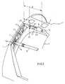
- a first security lock 15 is mounted on the internal face of the upstream frame 2 and cooperates with a complementary element 16 provided on the upstream edge 10 of the door.
- This 15-16 latch assembly can be of any type suitable and in particular of the type described and claimed in previous French patent application No. 2,683,860 of 14 November 1991.
- a second security lock 25 is provided to act between the beam 3 and the side edge 11 from the door.
- the latch 25 is constituted by a hook 28 articulated so pivoting at 29 on an axis integral with the lateral edge 8 of the beam.
- the notch 30 of the hook is intended to cooperate with a lug or pivot 26 (figure 1) formed on the edge side 11 of the door, in order to keep it in closed position.
- a device to prevent hook tipping similar to that provided for in the earlier patent application cited above is constituted by a finger 35 intended for cooperate with a hole 34 of the hook and subjected to the action of a solenoid (not shown) and extending transversely to the plane of the hook 28, said finger being permanently mounted in the wall of the edge 8 of the opening 5.
- the supply circuit of the actuating solenoid of the finger 35 is independent of the control circuit for locks 15 and 25.
- the prohibition finger 35 is constantly pressed by a spring (not shown) in the extended position and takes press against the full face of the hook 28 when the latter is in the open position (position in solid line in the figure 4) caused by the jack 31 to release the door when you want to use the reverse thrust position.
- the pivot 26 causes the hook 28 to tilt in its broken line position in Figure 4 and as soon that finger 35 is opposite hole 34, it enters automatically in the hole under the action of its spring.
- the unlocking the lock can only occur if the solenoid of finger 35 is activated voluntarily via its control circuit. Note that thanks to this arrangement, if the solenoid cannot be activated afterwards for example the destruction of its power circuit, the lock remains blocked by finger 35 and cannot pivot under the action of the cylinder 31, which prohibits the opening of the door.
- the latch hook 28 is disposed between the door pivot and the annular frame 2 of the fixed structure.
- the pivot 26 intended to cooperate with the hook 28 is located between the door pivot 12 and the upstream edge of the door (see figure 1).
- the distance d ( Figures 2 and 3) between latch 25 and edge 6 of the upstream frame 2 is advantageously between half and a quarter of the distance "D" between the door pivot 12 and the edge 6 of the frame 2. The same goes naturally for the position of the pivot 26 on the side edge of the door.
- this disc 200 is located in the immediate vicinity of plane P.
- the angle between arrows 210 and 220 is the one that is commonly admitted.
- the frame and the locks 15 as well as the cylinders 13 may be damaged while that the latches 25 will remain outside the trajectory. Yes the lock 25 was located further forward, that is to say in the first quarter of the distance "D", it could be also deteriorated.
- the privileged position of the lock in the "ZO" zone located between the half D / 2 and the quarter D / 4 upstream of the distance "D" therefore combines maximum security by putting the lock 25 protected from deterioration and conditions of optimal mechanical work of the lock.
Landscapes
- Engineering & Computer Science (AREA)
- Mechanical Engineering (AREA)
- General Engineering & Computer Science (AREA)
- Chemical & Material Sciences (AREA)
- Combustion & Propulsion (AREA)
- Lock And Its Accessories (AREA)
- Superstructure Of Vehicle (AREA)
Description
- la figure 1 est une vue en perspective générale d'un arrière-corps de capotage pour moteur d'avion équipé d'une installation d'inversion de poussée ;
- la figure 2 est un détail à plus grande échelle de l'ouverture de déviation du flux de gaz moteur d'un moteur équipé du système de sécurité de l'invention ;
- la figure 3 est un schéma illustrant un incident de fonctionnement du moteur ; et
- la figure 4 est un détail à plus grande échelle d'une forme de réalisation préférée d'un verrou selon l'invention.
Claims (10)
- Installation d'inversion de poussée à portes pour moteur d'avion du type à réaction, ladite installation présentant une série de portes basculantes (9) articulées autour de pivots (12) dans une structure fixe d'un capotage entourant le moteur à peu près concentriquement à l'axe longitudinal (X-X) dudit moteur, lesdites portes (9) étant susceptibles de basculer, sous l'action d'un vérin de commande (13), entre une position escamotée dite "de croisière" dans laquelle elles obturent des ouvertures (5) pratiquées dans la structure fixe du capotage et une position déployée dite "d'inversion" dans laquelle lesdites portes (9) font saillie radialement vers l'extérieur du capotage en dégageant lesdites ouvertures (5) par lesquelles le flux de gaz moteur peut être dévié radialement vers l'extérieur, ladite installation d'inversion comportant un système de sécurité de portes destiné à interdire l'ouverture intempestive des portes d'inverseur, ledit système de sécurité étant constitué, pour chaque porte (9), d'au moins deux verrous indépendants (15, 25), chaque verrou agissant respectivement entre la structure fixe du capotage (6-8) et une partie de la porte (9), l'installation étant caractérisée en ce que
lesdits verrous (15,25) associés à chaque porte (9) sont, d'une part, écartés l'un de l'autre dans le sens de l'axe longitudinal (X-X) du moteur de façon à se trouver dans deux plans transversaux distincts et écartés et, d'autre part, associés respectivement à des circuits de commande d'ouverture indépendants l'un de l'autre. - Installation d'inversion selon la revendication 1 dans laquelle les portes (9) et les ouvertures (5) du capotage dans lesquelles elles sont logées ont une forme générale à peu près rectangulaire, caractérisée en ce que les deux verrous (15, 25) sont disposés respectivement sur deux côtés adjacents (6, 8) de chaque ouverture (5) de capotage.
- Installation selon les revendications 1 et 2 dans laquelle la structure fixe de capotage présente un cadre annulaire amont (2) (par rapport au sens de circulation (F) des gaz) et des poutres longitudinales (3) délimitant respectivement les bords amont (6) et latéraux (8) des ouvertures (5) du capotage, caractérisée en ce que l'un des verrous (15) est monté sur le cadre annulaire amont (2) pour coopérer avec un élément complémentaire (16) du bord amont (10) de la porte (9), tandis que l'autre verrou (25) est monté sur une poutre longitudinale (3) pour coopérer avec un élément de verrou complémentaire (26) ménagé dans le bord latéral (11) de la porte.
- Installation selon la revendication 3 dans laquelle les pivots (12) de porte sont logés dans les poutres longitudinales (3), caractérisée en ce que les verrous (25) montés sur les poutres (3) sont situés dans l'espace compris entre le pivot (12) de porte et le cadre annulaire amont (2).
- Installation selon la revendication 4, caractérisée en ce que la distance (d) entre le verrou (25) et le cadre amont (2) est inférieure ou égale à la moitié de la distance (D) entre le cadre amont (2) et le pivot (12) de porte.
- Installation selon l'une quelconque des revendications 4 ou 5, caractérisée en ce que le verrou (25) est situé à une distance (d) du cadre amont (2) comprise entre la moitié et le quart de la distance (D) entre le cadre amont (2) et le pivot (12) de porte.
- Installation selon la revendication 6, caractérisée en ce que l'élément complémentaire (26) de verrou (25) est situé à une distance (d) du bord amont (10) de porte comprise entre la moitié et le quart de la distance (D) entre le bord amont (10) et le pivot (12) de porte.
- Installation selon l'une quelconque des revendications 3 à 7, caractérisée en ce que le verrou (25) monté sur la poutre (3) de capotage a la forme d'un crochet (28) pivotant et l'élément complémentaire (26) de verrou porté par la porte est un ergot fixe.
- Installation selon l'une quelconque des revendications 3 à 8, caractérisée en ce que, en position de porte fermée, le verrou (25) monté sur la poutre (3) de capotage, une fois en prise avec l'élément complémentaire (26) de verrou, est immobilisé en position par un mécanisme de blocage (35) automatique qui ne peut être libéré que par une action volontaire sur un circuit de commande indépendant de l'actionnement du verrou (25).
- Installation selon l'une quelconque des revendications précédentes dans laquelle le basculement des portes (9) est réalisé par des vérins (13), chaque porte (9) étant attelée à un vérin (13), caractérisée en ce que ledit vérin constitue lui-même un troisième verrou de sécurité pour interdire l'ouverture intempestive de la porte grâce à un moyen de verrouillage (14) qu'il contient.
Applications Claiming Priority (2)
| Application Number | Priority Date | Filing Date | Title |
|---|---|---|---|
| FR9313835A FR2712635B1 (fr) | 1993-11-19 | 1993-11-19 | Inverseur de poussée à portes pour moteur d'avion équipé de systèmes de sécurité interdisant l'ouverture intempestive des portes. |
| FR9313835 | 1993-11-19 |
Publications (2)
| Publication Number | Publication Date |
|---|---|
| EP0656469A1 EP0656469A1 (fr) | 1995-06-07 |
| EP0656469B1 true EP0656469B1 (fr) | 1998-08-12 |
Family
ID=9453028
Family Applications (1)
| Application Number | Title | Priority Date | Filing Date |
|---|---|---|---|
| EP19940402142 Expired - Lifetime EP0656469B1 (fr) | 1993-11-19 | 1994-09-27 | Installation de sécurité pour inverseur de poussée |
Country Status (3)
| Country | Link |
|---|---|
| EP (1) | EP0656469B1 (fr) |
| DE (1) | DE69412436T2 (fr) |
| FR (1) | FR2712635B1 (fr) |
Families Citing this family (6)
| Publication number | Priority date | Publication date | Assignee | Title |
|---|---|---|---|---|
| FR2761733B1 (fr) * | 1997-04-03 | 1999-06-11 | Hispano Suiza Sa | Inverseur de poussee pour turbomoteur d'aeronef |
| FR2765916B1 (fr) * | 1997-07-10 | 1999-08-20 | Hispano Suiza Sa | Inverseur de poussee a resistance amelioree aux impacts |
| US6554224B2 (en) * | 2001-08-31 | 2003-04-29 | The Boeing Company | Out-of-plane thrust reverser sleeve lock |
| DE102008045851A1 (de) * | 2008-09-05 | 2010-03-11 | Rolls-Royce Deutschland Ltd & Co Kg | Vorrichtung zum Öffnen und Schließen einer Schubumkehrertür eines Strahltriebwerks |
| DE102011008918A1 (de) * | 2011-01-19 | 2012-07-19 | Rolls-Royce Deutschland Ltd & Co Kg | Fluggasturbinenschubumkehrvorrichtung |
| FR3079213B1 (fr) * | 2018-03-23 | 2020-02-28 | Airbus Operations | Nacelle equipee d'un systeme inverseur comportant des portes et des systemes anti-vibration des portes en position stockee |
Family Cites Families (3)
| Publication number | Priority date | Publication date | Assignee | Title |
|---|---|---|---|---|
| FR2494775B1 (fr) * | 1980-11-27 | 1985-07-05 | Astech | Dispositif pour la commande d'un inverseur de poussee pour moteur a reaction |
| FR2500537B1 (fr) * | 1981-02-24 | 1985-07-05 | Astech | Dispositif de securite pour inverseur de poussee associe a un moteur a reaction d'aeronef |
| FR2683860B1 (fr) * | 1991-11-14 | 1995-04-28 | Hurel Dubois Avions | Installation de securite pour inverseur de poussee a portes equipant un avion et ensemble incorporant une telle installation. |
-
1993
- 1993-11-19 FR FR9313835A patent/FR2712635B1/fr not_active Expired - Lifetime
-
1994
- 1994-09-27 EP EP19940402142 patent/EP0656469B1/fr not_active Expired - Lifetime
- 1994-09-27 DE DE1994612436 patent/DE69412436T2/de not_active Expired - Lifetime
Also Published As
| Publication number | Publication date |
|---|---|
| DE69412436D1 (de) | 1998-09-17 |
| FR2712635B1 (fr) | 1996-08-09 |
| DE69412436T2 (de) | 1999-04-29 |
| EP0656469A1 (fr) | 1995-06-07 |
| FR2712635A1 (fr) | 1995-05-24 |
Similar Documents
| Publication | Publication Date | Title |
|---|---|---|
| CA2225608C (fr) | Inverseur de poussee de turboreacteur a double flux a coquilles aval | |
| EP0846854B1 (fr) | Inverseur de poussée de turboréacteur à portes maintenues dans les lignes de nacelle | |
| CA2213049C (fr) | Inverseur de poussee de turboreacteur a portes formant ecopes | |
| EP0757170B1 (fr) | Inverseur de poussée de turboréacteur à une coquille | |
| EP0869272B1 (fr) | Inverseur de poussée protégé au déverrouillage pour turbomoteur d'aéronef | |
| EP0828934B1 (fr) | Ensemble d'inverseur de poussee a deux portes | |
| EP2640639B1 (fr) | Structure de renforcement d'une nacelle de turboréacteur | |
| CA2780058A1 (fr) | Ensemble pour turboreacteur d'aeronef comprenant un capot d'inversion de pousee | |
| EP3732360B1 (fr) | Inverseur de poussée à grilles pour turboréacteur | |
| WO1999002843A1 (fr) | Inverseur de poussee resistant aux impacts | |
| WO2008139048A2 (fr) | Nacelle pour turboreacteur equipee d'un systeme d'inversion de poussee a une seule porte | |
| FR2835870A1 (fr) | Systeme de fermeture interpose entre deux elements | |
| EP0656469B1 (fr) | Installation de sécurité pour inverseur de poussée | |
| EP0754849A1 (fr) | Inverseur de poussée de turboréacteur à double flux à portes dissymétriques | |
| FR2846376A1 (fr) | Platine de maintenance et d'inhibition pour inverseur de poussee | |
| EP0835999B1 (fr) | Inverseur de poussée à portes à installation de vérin de commande optimisée | |
| EP2971730B1 (fr) | Dispositif d'inhibition mécanique intégré à une ligne de défense d'un inverseur de poussée | |
| FR2683860A1 (fr) | Installation de securite pour inverseur de poussee a portes equipant un avion et ensemble incorporant une telle installation. | |
| EP0821151A1 (fr) | Inverseur de poussée de turboréacteur à portes comportant un panneau coulissant | |
| EP2232040A2 (fr) | Inverseur de poussée à portes pour turboréacteur | |
| FR2717859A1 (fr) | Turbomoteur à double flux équipé d'un système d'inversion de poussée et d'un dispositif de restriction du canal d'éjection des gaz froids, et dispositif de restriction équipant un tel turbomoteur. | |
| FR2526872A1 (fr) | Inverseur de poussee a porte notamment pour moteur d'avion a reaction | |
| FR3151838A1 (fr) | Verrou pour nacelle d’ensemble propulsif | |
| FR3147311A1 (fr) | Verrou pour nacelle de turbomachine |
Legal Events
| Date | Code | Title | Description |
|---|---|---|---|
| PUAI | Public reference made under article 153(3) epc to a published international application that has entered the european phase |
Free format text: ORIGINAL CODE: 0009012 |
|
| AK | Designated contracting states |
Kind code of ref document: A1 Designated state(s): DE GB |
|
| 17P | Request for examination filed |
Effective date: 19951110 |
|
| 17Q | First examination report despatched |
Effective date: 19970307 |
|
| GRAG | Despatch of communication of intention to grant |
Free format text: ORIGINAL CODE: EPIDOS AGRA |
|
| GRAG | Despatch of communication of intention to grant |
Free format text: ORIGINAL CODE: EPIDOS AGRA |
|
| GRAH | Despatch of communication of intention to grant a patent |
Free format text: ORIGINAL CODE: EPIDOS IGRA |
|
| GRAH | Despatch of communication of intention to grant a patent |
Free format text: ORIGINAL CODE: EPIDOS IGRA |
|
| GRAA | (expected) grant |
Free format text: ORIGINAL CODE: 0009210 |
|
| AK | Designated contracting states |
Kind code of ref document: B1 Designated state(s): DE GB |
|
| REF | Corresponds to: |
Ref document number: 69412436 Country of ref document: DE Date of ref document: 19980917 |
|
| GBT | Gb: translation of ep patent filed (gb section 77(6)(a)/1977) |
Effective date: 19981008 |
|
| PLBE | No opposition filed within time limit |
Free format text: ORIGINAL CODE: 0009261 |
|
| STAA | Information on the status of an ep patent application or granted ep patent |
Free format text: STATUS: NO OPPOSITION FILED WITHIN TIME LIMIT |
|
| 26N | No opposition filed | ||
| REG | Reference to a national code |
Ref country code: GB Ref legal event code: IF02 |
|
| PGFP | Annual fee paid to national office [announced via postgrant information from national office to epo] |
Ref country code: DE Payment date: 20130726 Year of fee payment: 20 |
|
| PGFP | Annual fee paid to national office [announced via postgrant information from national office to epo] |
Ref country code: GB Payment date: 20130730 Year of fee payment: 20 |
|
| REG | Reference to a national code |
Ref country code: DE Ref legal event code: R071 Ref document number: 69412436 Country of ref document: DE |
|
| REG | Reference to a national code |
Ref country code: DE Ref legal event code: R071 Ref document number: 69412436 Country of ref document: DE |
|
| REG | Reference to a national code |
Ref country code: GB Ref legal event code: PE20 Expiry date: 20140926 |
|
| PG25 | Lapsed in a contracting state [announced via postgrant information from national office to epo] |
Ref country code: DE Free format text: LAPSE BECAUSE OF EXPIRATION OF PROTECTION Effective date: 20140930 |
|
| PG25 | Lapsed in a contracting state [announced via postgrant information from national office to epo] |
Ref country code: GB Free format text: LAPSE BECAUSE OF EXPIRATION OF PROTECTION Effective date: 20140926 |