EP0656495B1 - Distributeur de liquide fonctionnant avec des électrovannes - Google Patents
Distributeur de liquide fonctionnant avec des électrovannes Download PDFInfo
- Publication number
- EP0656495B1 EP0656495B1 EP94420333A EP94420333A EP0656495B1 EP 0656495 B1 EP0656495 B1 EP 0656495B1 EP 94420333 A EP94420333 A EP 94420333A EP 94420333 A EP94420333 A EP 94420333A EP 0656495 B1 EP0656495 B1 EP 0656495B1
- Authority
- EP
- European Patent Office
- Prior art keywords
- liquid
- distributor
- solenoid valves
- solenoid valve
- valve
- Prior art date
- Legal status (The legal status is an assumption and is not a legal conclusion. Google has not performed a legal analysis and makes no representation as to the accuracy of the status listed.)
- Expired - Lifetime
Links
- 239000007788 liquid Substances 0.000 title claims description 50
- XLYOFNOQVPJJNP-UHFFFAOYSA-N water Substances O XLYOFNOQVPJJNP-UHFFFAOYSA-N 0.000 claims description 50
- 238000005406 washing Methods 0.000 claims description 5
- 230000000694 effects Effects 0.000 claims description 3
- 238000011144 upstream manufacturing Methods 0.000 claims description 3
- 238000009434 installation Methods 0.000 description 3
- 235000021183 entrée Nutrition 0.000 description 2
- 238000007789 sealing Methods 0.000 description 2
- 240000008042 Zea mays Species 0.000 description 1
- 230000006835 compression Effects 0.000 description 1
- 238000007906 compression Methods 0.000 description 1
- 230000007547 defect Effects 0.000 description 1
- 239000000463 material Substances 0.000 description 1
- 210000000056 organ Anatomy 0.000 description 1
- 230000001105 regulatory effect Effects 0.000 description 1
- 230000000717 retained effect Effects 0.000 description 1
Images


Classifications
-
- F—MECHANICAL ENGINEERING; LIGHTING; HEATING; WEAPONS; BLASTING
- F16—ENGINEERING ELEMENTS AND UNITS; GENERAL MEASURES FOR PRODUCING AND MAINTAINING EFFECTIVE FUNCTIONING OF MACHINES OR INSTALLATIONS; THERMAL INSULATION IN GENERAL
- F16K—VALVES; TAPS; COCKS; ACTUATING-FLOATS; DEVICES FOR VENTING OR AERATING
- F16K39/00—Devices for relieving the pressure on the sealing faces
- F16K39/02—Devices for relieving the pressure on the sealing faces for lift valves
- F16K39/024—Devices for relieving the pressure on the sealing faces for lift valves using an auxiliary valve on the main valve
-
- F—MECHANICAL ENGINEERING; LIGHTING; HEATING; WEAPONS; BLASTING
- F16—ENGINEERING ELEMENTS AND UNITS; GENERAL MEASURES FOR PRODUCING AND MAINTAINING EFFECTIVE FUNCTIONING OF MACHINES OR INSTALLATIONS; THERMAL INSULATION IN GENERAL
- F16K—VALVES; TAPS; COCKS; ACTUATING-FLOATS; DEVICES FOR VENTING OR AERATING
- F16K11/00—Multiple-way valves, e.g. mixing valves; Pipe fittings incorporating such valves
- F16K11/10—Multiple-way valves, e.g. mixing valves; Pipe fittings incorporating such valves with two or more closure members not moving as a unit
- F16K11/20—Multiple-way valves, e.g. mixing valves; Pipe fittings incorporating such valves with two or more closure members not moving as a unit operated by separate actuating members
- F16K11/24—Multiple-way valves, e.g. mixing valves; Pipe fittings incorporating such valves with two or more closure members not moving as a unit operated by separate actuating members with an electromagnetically-operated valve, e.g. for washing machines
-
- Y—GENERAL TAGGING OF NEW TECHNOLOGICAL DEVELOPMENTS; GENERAL TAGGING OF CROSS-SECTIONAL TECHNOLOGIES SPANNING OVER SEVERAL SECTIONS OF THE IPC; TECHNICAL SUBJECTS COVERED BY FORMER USPC CROSS-REFERENCE ART COLLECTIONS [XRACs] AND DIGESTS
- Y10—TECHNICAL SUBJECTS COVERED BY FORMER USPC
- Y10T—TECHNICAL SUBJECTS COVERED BY FORMER US CLASSIFICATION
- Y10T137/00—Fluid handling
- Y10T137/0318—Processes
- Y10T137/0324—With control of flow by a condition or characteristic of a fluid
- Y10T137/0329—Mixing of plural fluids of diverse characteristics or conditions
- Y10T137/0352—Controlled by pressure
-
- Y—GENERAL TAGGING OF NEW TECHNOLOGICAL DEVELOPMENTS; GENERAL TAGGING OF CROSS-SECTIONAL TECHNOLOGIES SPANNING OVER SEVERAL SECTIONS OF THE IPC; TECHNICAL SUBJECTS COVERED BY FORMER USPC CROSS-REFERENCE ART COLLECTIONS [XRACs] AND DIGESTS
- Y10—TECHNICAL SUBJECTS COVERED BY FORMER USPC
- Y10T—TECHNICAL SUBJECTS COVERED BY FORMER US CLASSIFICATION
- Y10T137/00—Fluid handling
- Y10T137/8593—Systems
- Y10T137/87249—Multiple inlet with multiple outlet
-
- Y—GENERAL TAGGING OF NEW TECHNOLOGICAL DEVELOPMENTS; GENERAL TAGGING OF CROSS-SECTIONAL TECHNOLOGIES SPANNING OVER SEVERAL SECTIONS OF THE IPC; TECHNICAL SUBJECTS COVERED BY FORMER USPC CROSS-REFERENCE ART COLLECTIONS [XRACs] AND DIGESTS
- Y10—TECHNICAL SUBJECTS COVERED BY FORMER USPC
- Y10T—TECHNICAL SUBJECTS COVERED BY FORMER US CLASSIFICATION
- Y10T137/00—Fluid handling
- Y10T137/8593—Systems
- Y10T137/877—With flow control means for branched passages
- Y10T137/87829—Biased valve
- Y10T137/87837—Spring bias
- Y10T137/87861—Spring coaxial with valve
- Y10T137/87869—Biased open
-
- Y—GENERAL TAGGING OF NEW TECHNOLOGICAL DEVELOPMENTS; GENERAL TAGGING OF CROSS-SECTIONAL TECHNOLOGIES SPANNING OVER SEVERAL SECTIONS OF THE IPC; TECHNICAL SUBJECTS COVERED BY FORMER USPC CROSS-REFERENCE ART COLLECTIONS [XRACs] AND DIGESTS
- Y10—TECHNICAL SUBJECTS COVERED BY FORMER USPC
- Y10T—TECHNICAL SUBJECTS COVERED BY FORMER US CLASSIFICATION
- Y10T137/00—Fluid handling
- Y10T137/8593—Systems
- Y10T137/877—With flow control means for branched passages
- Y10T137/87877—Single inlet with multiple distinctly valved outlets
Definitions
- the present invention relates to a dispenser for liquid working with solenoid valves, constituting including a water dispenser for household appliances such as washing machine or dishwasher, allowing to selectively direct a flow of liquid towards multiple exit routes.
- This liquid dispenser including water, is of the type comprising at least one liquid inlet, preferably at least two inlet liquid, which are associated respectively with controlled valves, and at least two liquid outlets. Insofar as it has two or more inputs, this distributor of liquid can also constitute a mixer.
- liquid dispensers of this kind are used in household appliances such as washing machine and dishwasher, for direct water, when needed, to either of two or more routes.
- the water dispensers currently used in this area application, can provide a water flow of 0.3 to 20 liters / minute, with a pressure between 0.2 and 10 bars.
- a water dispenser of this kind is described by example in document US-A-4270570, which relates more particularly a mixer with a water inlet hot, cold water inlet, and double outlet of water delivering, selectively, a low flow of water or high water flow, three solenoid valves being provided respectively on the two inputs and on the output.
- Document DE-A-3919245 describes a dispenser of water for vehicle washing installation, with a number of water inlet and outlet fittings.
- This distributor has a number of components for control and metering, some of these components being solenoid valves.
- the solenoid valves are here spread over the whole extent of the shaped distributor of plate, in particular at the branching of channels internal, and are not arranged at the entrances and liquid outlets.
- document DE-A-3619245 does not specify what type of solenoid valves are used.
- the present invention aims to avoid disadvantages of current liquid dispensers, particularly linked to piloted solenoid valves, by supplying a liquid dispenser of different design, which be simpler, more compact and less expensive, while having a very satisfactory functioning.
- the subject of the invention is a liquid dispenser of the kind specified in the introduction, and having the characteristics of the characterizing part of claim 1.
- the operating principle of this dispenser of liquid consists in cutting off the liquid supply in upstream, by means of at least one controlled valve (normal or ) then put the different solenoid valves distributor in open or closed position, depending on liquid outlets to be used momentarily, before reopening said controlled valve in order to leave the liquid flow through the desired outlet (s), running through the body of the dispenser.
- the safety valve the pressure residual inside the distributor body (at time of actuation of the action solenoid valves direct) is weak, and allows the proper functioning of solenoid valves.
- this safety valve allows to make the liquid distributor with materials having just enough breaking strength to resist the residual pressure, so to make this distributor economically.
- An advantage additional safety valve is to allow the removal of a solenoid valve, using the passage of the liquid through this valve to supply one of the outlets of liquid, hence simplification and economy additional.
- At least part of the liquid outlets can be equipped with flow regulators.
- the distributor of liquid comprises at least one action solenoid valve direct, including a normally open solenoid valve associated with a liquid outlet, including the sealing gasket is pierced with a small central hole, suitable for closing or released by a head from the movable core of the solenoid valve, so as to allow the return of this solenoid valve in rest position, in particular under the effect of its spring even in the event of a high residual pressure at inside the distributor body.
- This provision allows the solenoid valve to be opened in two stages, and certain, by creating an initial leak through the small hole of the obturator seal, even if this seal is applied on the corresponding outlet by a force does not allowing its direct detachment by force solenoid return spring. So the distributor liquid can still be reconditioned operation.
- liquid dispenser object of the present invention constitutes a water dispenser, for electro-manager device such as washing machine or dishwasher
- the different solenoid valves are controlled, at the desired time, from the device programmer.
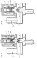
- the water dispenser represented in its together in Figures 1 and 2, includes a hollow body 1 provided on one side with several water inlets, either in the example considered three water inlets 2a, 2b and 2c.
- This water dispenser has, on its opposite side, multiple water outlets 3.3a, 3b, 3c, 3d and 3e, constituted by a set of tubular tips attached to the body 1.
- Solenoid valves 4,5a, 5b and 5c are directly attached to the body 1 of the water dispenser.
- Some water outlets 3a, 3b and 3c are here equipped with respective flow regulators 6, 7 and 8, made in the form of calibrated orifices.
- the safety valve 9 On the body 1 of the water distributor is mounted a safety valve 9, adapted to an opening 10 in the body 1.
- the safety valve 9 includes a seal 11, normally applied against the edge of the opening 10 by a spring 12 which itself rests on a member of adjustment 13 screwable.
- a valve On the first water inlet 2a is connected a inlet duct 14, on which a valve is placed safety 15 electric, mechanical, magnetic or pneumatic, here represented as being a solenoid valve, with which is associated a filter and / or a flow regulator 16.
- safety 15 electric, mechanical, magnetic or pneumatic, here represented as being a solenoid valve, with which is associated a filter and / or a flow regulator 16.
- the water pressure inside the body 1 water dispenser must be zero or less than 0.1 bar (indicative value).
- the arrival of water under pressure inside the body 1 is cut upstream by action on the safety valve 15 (or on the valves 15 and 18 in the case of water inlets multiple).
- the solenoid valves 4,5a, 5b and 5c are each put in the desired position, to seal or release the corresponding water outlets 3 to 3e. Finally, the safety valve 15 (or the two safety valves safety 15 and 18), to allow free flow water through the desired outlet (s).
- the movable core 23 of the solenoid valve 4 has a head 24 capable of closing off the entrance to hole 22 (see Figure 3) or to deviate from it slightly, the head 24 being retained in a housing formed on the seal 20, in the region of the aforementioned hole 22. At least one channel is provided in the wall of this housing 25, putting this housing in communication with the interior of the body 1 of the distributor.
- Such a seal with hole can also be provided on the normally closed solenoid valves 5a, 5b and 5c, but the advantage obtained is in this case of less importance because to restore the water dispenser to normal operation, it is necessary to power these solenoid valves in electric current.
- this distributor can also be used as a mixer, for example with an entrance receiving hot water and a another entrance receiving cold water.
Landscapes
- Engineering & Computer Science (AREA)
- General Engineering & Computer Science (AREA)
- Mechanical Engineering (AREA)
- Physics & Mathematics (AREA)
- Electromagnetism (AREA)
- Magnetically Actuated Valves (AREA)
- Accessories For Mixers (AREA)
- Safety Valves (AREA)
Description
- Une première électrovanne normalement fermée 5a est associée aux trois sorties d'eau 3a,3b et 3c.
- Une deuxième électrovanne normalement fermée 5b est associée à la sortie d'eau 3d.
- Une troisième électrovanne normalement fermée 5c est associée à la dernière sortie d'eau 3e.
- en modifiant le nombre des entrées et des sorties de liquide,
- en prévoyant toutes combinaisons d'électrovannes normalement ouvertes et/ou d'électrovannes normalement fermées,
- en associant aux entrées de liquide des vannes normales ou de sécurité commandées par tout moyen,
- en ajoutant sur ce distributeur tous organes de régulation ou de sécurité,
- en destinant un tel distributeur à des liquides autres que l'eau, dans des appareils ou installations de toute nature.
Claims (4)
- Distributeur de liquide fonctionnant avec des électrovannes, constituant notamment un distributeur d'eau pour appareil électro-ménager tel que lave-linge ou lave-vaisselle, comportant au moins une entrée de liquide, de préférence au moins deux entrées de liquide (2a,2b,2c), auxquelles sont associées respectivement des vannes commandées (15,18), et au moins deux sorties de liquide (3,3a,3b,3c,3d,3e), caractérisé en ce que : respectivement des électrovannes normalement ouvertes (4) et/ou des électrovannes normalement fermées (5a,5b,5c) sont associées aux sorties de liquide, les sorties de liquide étant ainsi aptes à être mises en communication sélectivement avec la ou les entrées de liquide, la vanne commandée (15,18), telle qu'une électrovanne, associée à la ou chaque entrée de liquide (2a,2b,2c) étant prévue pour couper l'arrivée de liquide (14,17) en amont de cette entrée (2a,2b,2c) avant actionnement sélectif des électrovannes (5,5a,5b,5c) associées aux sorties de liquide (3,3a,3b,3c,3d,3e); les électrovannes (4,5a,5b,5c), associées aux sorties de liquide (3,3a,3b,3c,3d,3e), sont toutes des électrovannes à action directe; et un clapet de sécurité (9), de préférence réglable, est monté sur le corps (1) du distributeur pour limiter la pression de liquide à l'intérieur de ce dernier.
- Distributeur de liquide selon la revendication 1, caractérisé en ce qu'au moins une partie des sorties de liquide (3a,3b,3c) sont équipées de régulateurs de débit (6,7,8).
- Distributeur de liquide selon la revendication 1 ou 2, caractérisé en ce qu'il comprend au moins une électrovanne à action directe, notamment une électrovanne normalement ouverte (4), associée à une sortie de liquide (3), dont le joint obturateur (20) est percé d'un petit trou central (22), apte à être obturé ou dégagé par une tête (24) du noyau mobile (23) de l'électrovanne, de manière à permettre le retour de cette électrovanne (4) en position de repos, notamment sous l'effet de son ressort de rappel (21), même en cas de pression résiduelle élevée à l'intérieur du corps (1) du distributeur.
- Distributeur de liquide selon la revendication 3, caractérisé en ce que la tête (24) du noyau mobile (23) de l'électrovanne à action directe (4) est retenue dans un logement formé sur le joint obturateur (20), dans la région du trou précité (22), au moins un canal (25) étant ménagé dans la paroi dudit logement pour mettre ce logement en communication avec l'intérieur du corps (1) du distributeur.
Applications Claiming Priority (2)
| Application Number | Priority Date | Filing Date | Title |
|---|---|---|---|
| FR9314623A FR2713302B1 (fr) | 1993-12-01 | 1993-12-01 | Distributeur de liquide fonctionnant avec des électrovannes. |
| FR9314623 | 1993-12-01 |
Publications (2)
| Publication Number | Publication Date |
|---|---|
| EP0656495A1 EP0656495A1 (fr) | 1995-06-07 |
| EP0656495B1 true EP0656495B1 (fr) | 1998-01-28 |
Family
ID=9453619
Family Applications (1)
| Application Number | Title | Priority Date | Filing Date |
|---|---|---|---|
| EP94420333A Expired - Lifetime EP0656495B1 (fr) | 1993-12-01 | 1994-11-30 | Distributeur de liquide fonctionnant avec des électrovannes |
Country Status (5)
| Country | Link |
|---|---|
| US (1) | US5605173A (fr) |
| EP (1) | EP0656495B1 (fr) |
| CA (1) | CA2137103A1 (fr) |
| DE (1) | DE69408288T2 (fr) |
| FR (1) | FR2713302B1 (fr) |
Families Citing this family (72)
| Publication number | Priority date | Publication date | Assignee | Title |
|---|---|---|---|---|
| WO1998059190A1 (fr) * | 1997-06-25 | 1998-12-30 | Karg Jeffrey A | Vanne de derivation de fluide |
| RU2137971C1 (ru) * | 1998-03-23 | 1999-09-20 | Новичков Юрий Михайлович | Распределительное электромагнитное устройство |
| GB2336650B (en) * | 1998-04-21 | 2000-03-08 | Cheng Chien Chuan | Distribution valve assembly |
| RU2164633C1 (ru) * | 1999-07-21 | 2001-03-27 | Савельев Борис Сергеевич | Пневмораспределитель |
| DE10066009B4 (de) * | 2000-07-27 | 2005-06-16 | Falch Hochdruckstrahlsysteme Gmbh | Hochdruckreinigungsgerät mit Druckverteiler für im wesentlichen ebene Flächen |
| US6691338B2 (en) * | 2001-04-06 | 2004-02-17 | Interbath, Inc. | Spa shower and controller |
| US6634173B2 (en) | 2001-10-22 | 2003-10-21 | Hale Products, Inc. | Hydraulic rescue system |
| US7114666B2 (en) | 2002-12-10 | 2006-10-03 | Water Pik, Inc. | Dual massage shower head |
| US6994726B2 (en) * | 2004-05-25 | 2006-02-07 | Calcitec, Inc. | Dual function prosthetic bone implant and method for preparing the same |
| US7533906B2 (en) | 2003-10-14 | 2009-05-19 | Water Pik, Inc. | Rotatable and pivotable connector |
| US7740186B2 (en) * | 2004-09-01 | 2010-06-22 | Water Pik, Inc. | Drenching shower head |
| US20070157975A1 (en) * | 2006-01-12 | 2007-07-12 | Malayev Andrei A | Generator of liquid media distribution pattern |
| US8733675B2 (en) | 2006-04-20 | 2014-05-27 | Water Pik, Inc. | Converging spray showerhead |
| US20070272770A1 (en) * | 2006-05-26 | 2007-11-29 | Water Pik, Inc. | Apparatus and methods for a showerhead bracket with integral showerhead |
| US7530728B2 (en) * | 2006-10-24 | 2009-05-12 | Lars Rosaen | Water control apparatus |
| ITMI20062042A1 (it) * | 2006-10-24 | 2008-04-25 | Ceme Spa | Elettrovalvola |
| USD577793S1 (en) | 2006-11-29 | 2008-09-30 | Water Pik, Inc. | Showerhead assembly |
| US8020787B2 (en) | 2006-11-29 | 2011-09-20 | Water Pik, Inc. | Showerhead system |
| USD577099S1 (en) | 2006-11-29 | 2008-09-16 | Water Pik, Inc. | Showerhead assembly |
| US7789326B2 (en) | 2006-12-29 | 2010-09-07 | Water Pik, Inc. | Handheld showerhead with mode control and method of selecting a handheld showerhead mode |
| US8794543B2 (en) | 2006-12-28 | 2014-08-05 | Water Pik, Inc. | Low-speed pulsating showerhead |
| US8366024B2 (en) | 2006-12-28 | 2013-02-05 | Water Pik, Inc. | Low speed pulsating showerhead |
| US7770822B2 (en) | 2006-12-28 | 2010-08-10 | Water Pik, Inc. | Hand shower with an extendable handle |
| US8371618B2 (en) | 2007-05-04 | 2013-02-12 | Water Pik, Inc. | Hidden pivot attachment for showers and method of making same |
| USD592278S1 (en) | 2007-12-20 | 2009-05-12 | Water Pik, Inc. | Showerhead |
| USD603935S1 (en) | 2007-12-20 | 2009-11-10 | Water Pik, Inc. | Hand shower |
| USD581014S1 (en) | 2007-12-20 | 2008-11-18 | Water Pik, Inc. | Hand shower |
| USD580012S1 (en) | 2007-12-20 | 2008-11-04 | Water Pik, Inc. | Showerhead |
| USD590048S1 (en) | 2007-12-20 | 2009-04-07 | Water Pik, Inc. | Hand shower |
| USD580513S1 (en) | 2007-12-20 | 2008-11-11 | Water Pik, Inc. | Hand shower |
| USD605731S1 (en) | 2007-12-26 | 2009-12-08 | Water Pik, Inc. | Bracket for hand shower |
| USD624156S1 (en) | 2008-04-30 | 2010-09-21 | Water Pik, Inc. | Pivot ball attachment |
| US8499789B2 (en) * | 2008-05-29 | 2013-08-06 | Tescom Corporation | Mobile gas supply system |
| CN101598224B (zh) * | 2008-06-02 | 2011-05-25 | 周瑛琪 | 万用型准流体系统 |
| CA2678769C (fr) | 2008-09-15 | 2014-07-29 | Water Pik, Inc. | Ensemble de douche avec changeur de mode radial |
| USD600777S1 (en) | 2008-09-29 | 2009-09-22 | Water Pik, Inc. | Showerhead assembly |
| USD606623S1 (en) | 2008-09-29 | 2009-12-22 | Water Pik, Inc. | Hand shower |
| USD616061S1 (en) | 2008-09-29 | 2010-05-18 | Water Pik, Inc. | Showerhead assembly |
| WO2010141013A1 (fr) * | 2009-06-02 | 2010-12-09 | Arne Fridtjof Myran | Système de vanne universelle |
| USD625776S1 (en) | 2009-10-05 | 2010-10-19 | Water Pik, Inc. | Showerhead |
| US8397763B2 (en) * | 2009-10-23 | 2013-03-19 | Bend Tech, LLC | Low pressure valve assembly |
| US8616470B2 (en) | 2010-08-25 | 2013-12-31 | Water Pik, Inc. | Mode control valve in showerhead connector |
| DE102010062262A1 (de) * | 2010-12-01 | 2012-06-06 | Zf Friedrichshafen Ag | Aktuator für eine verstellbare Dämpfventileinrichtung |
| CN102269284B (zh) * | 2011-08-01 | 2012-08-01 | 南昌大学 | 电磁阀 |
| USD678467S1 (en) | 2012-01-27 | 2013-03-19 | Water Pik, Inc. | Ring-shaped handheld showerhead |
| USD678463S1 (en) | 2012-01-27 | 2013-03-19 | Water Pik, Inc. | Ring-shaped wall mount showerhead |
| CA2976867C (fr) | 2012-06-22 | 2021-03-02 | Water Pik, Inc. | Support pour pomme de douche avec regulation de debit integree |
| US9404243B2 (en) | 2013-06-13 | 2016-08-02 | Water Pik, Inc. | Showerhead with turbine driven shutter |
| ITTO20130545A1 (it) * | 2013-07-01 | 2015-01-02 | Elbi Int Spa | Dispositivo valvolare per un sistema acquastop atto ad essere impiegato in un apparecchio elettrodomestico, quale una macchina lavastoviglie od una macchina lavabiancheria. |
| USD744612S1 (en) | 2014-06-13 | 2015-12-01 | Water Pik, Inc. | Handheld showerhead |
| USD744064S1 (en) | 2014-06-13 | 2015-11-24 | Water Pik, Inc. | Handheld showerhead |
| USD744066S1 (en) | 2014-06-13 | 2015-11-24 | Water Pik, Inc. | Wall mount showerhead |
| USD745111S1 (en) | 2014-06-13 | 2015-12-08 | Water Pik, Inc. | Wall mount showerhead |
| USD744611S1 (en) | 2014-06-13 | 2015-12-01 | Water Pik, Inc. | Handheld showerhead |
| USD744065S1 (en) | 2014-06-13 | 2015-11-24 | Water Pik, Inc. | Handheld showerhead |
| USD744614S1 (en) | 2014-06-13 | 2015-12-01 | Water Pik, Inc. | Wall mount showerhead |
| US9791152B2 (en) * | 2014-07-28 | 2017-10-17 | Lincoln Brass Works, Inc. | Regulator/magnetic control valve combination |
| CN104373636A (zh) * | 2014-10-17 | 2015-02-25 | 金华市宏昌电器有限公司 | 一种进水电磁阀 |
| USD803981S1 (en) | 2016-02-01 | 2017-11-28 | Water Pik, Inc. | Handheld spray nozzle |
| CN108883426B (zh) | 2016-02-01 | 2021-04-27 | 洁碧有限公司 | 手持式宠物用喷射棒 |
| US10265710B2 (en) | 2016-04-15 | 2019-04-23 | Water Pik, Inc. | Showerhead with dual oscillating massage |
| USD970684S1 (en) | 2016-04-15 | 2022-11-22 | Water Pik, Inc. | Showerhead |
| DE102016210851A1 (de) * | 2016-06-17 | 2017-12-21 | Hamilton Bonaduz Ag | Fluidversorgungsschnittstelle mit Sicherheitsventil für eine Zellkulturanlage, Verwendung einer solchen Fluidversorgungsschnittstelle zur Bewirtschaftung von Zellkulturbehältern und Zellkultur-Bewirtschaftungsanlage |
| WO2018049213A1 (fr) | 2016-09-08 | 2018-03-15 | Water Pik, Inc. | Ensemble pause pour pommes de douche |
| CN110073132A (zh) * | 2016-12-14 | 2019-07-30 | 丹佛斯有限公司 | 阀布置、管道布置以及空气调节系统 |
| US11053628B2 (en) | 2017-07-07 | 2021-07-06 | Whirlpool Corporation | Water supply circuit for a laundry treating appliance |
| USD843549S1 (en) | 2017-07-19 | 2019-03-19 | Water Pik, Inc. | Handheld spray nozzle |
| USD872227S1 (en) | 2018-04-20 | 2020-01-07 | Water Pik, Inc. | Handheld spray device |
| US11208080B2 (en) | 2019-05-20 | 2021-12-28 | Ford Global Technologies, Llc | Manifold for vehicle sensor cleaning |
| DE112020000106T5 (de) * | 2019-11-13 | 2021-07-15 | Langfang Golden Time Technology Development Co., Ltd. | Pumpenventilmodul und dessen Betriebsverfahren, Magnetventil-basiertesPumpenventilmodul zur Bereitstellung einer Massagefunktion für einen Fahrzeugsitz,sowie Fahrzeugsitz |
| FR3106508B1 (fr) * | 2020-01-28 | 2022-01-21 | Valeo Systemes Dessuyage | Systeme de projection de liquide |
| CN111623149B (zh) * | 2020-06-04 | 2022-03-25 | 上海科勒电子科技有限公司 | 电磁分配器及坐便器 |
Family Cites Families (10)
| Publication number | Priority date | Publication date | Assignee | Title |
|---|---|---|---|---|
| GB190927720A (en) * | 1909-11-29 | 1910-11-29 | John Auld | Improvements in and relating to Stop Valves. |
| US3392747A (en) * | 1965-08-27 | 1968-07-16 | Borg Warner | Convenience water outlet in an automatic washer and the like |
| US3989222A (en) * | 1975-07-28 | 1976-11-02 | Fumiya Yoshiyasu | Solenoid valve |
| US4280532A (en) * | 1978-05-17 | 1981-07-28 | Robertshaw Controls Company | Control unit and method of making the same |
| US4270570A (en) * | 1979-10-15 | 1981-06-02 | Eaton Corporation | Valve assembly |
| US4444215A (en) * | 1981-07-02 | 1984-04-24 | Eaton Corporation | Mixing valve |
| JPS58160679A (ja) * | 1982-03-18 | 1983-09-24 | Aisin Seiki Co Ltd | エアランバ−サポ−トバルブ |
| US4495968A (en) * | 1982-07-16 | 1985-01-29 | Combined Fluid Products Company | Pneumatic control system |
| AT391179B (de) * | 1987-03-06 | 1990-08-27 | Weber Gisela | Ventilbaugruppe |
| DE3919245A1 (de) * | 1989-06-13 | 1990-12-20 | Kleindienst Gmbh | Wasserbatterie |
-
1993
- 1993-12-01 FR FR9314623A patent/FR2713302B1/fr not_active Expired - Fee Related
-
1994
- 1994-11-23 US US08/344,436 patent/US5605173A/en not_active Expired - Fee Related
- 1994-11-30 EP EP94420333A patent/EP0656495B1/fr not_active Expired - Lifetime
- 1994-11-30 DE DE69408288T patent/DE69408288T2/de not_active Expired - Fee Related
- 1994-12-01 CA CA002137103A patent/CA2137103A1/fr not_active Abandoned
Also Published As
| Publication number | Publication date |
|---|---|
| US5605173A (en) | 1997-02-25 |
| DE69408288D1 (de) | 1998-03-05 |
| CA2137103A1 (fr) | 1995-06-02 |
| FR2713302A1 (fr) | 1995-06-09 |
| FR2713302B1 (fr) | 1996-03-01 |
| DE69408288T2 (de) | 1998-05-14 |
| EP0656495A1 (fr) | 1995-06-07 |
Similar Documents
| Publication | Publication Date | Title |
|---|---|---|
| EP0656495A1 (fr) | Distributeur de liquide fonctionnant avec des électrovannes | |
| EP3362716A1 (fr) | Vanne fluidique a hysteresis | |
| FR2612274A1 (fr) | Vanne distributrice | |
| FR3062552A1 (fr) | Dispositif de diffusion d'un produit encapsule dans un fluide | |
| FR2781032A1 (fr) | Dispositif de regulation du debit d'eau avec moyen de decharge de pression | |
| CH670688A5 (fr) | ||
| CH658110A5 (fr) | Dispositif de melange thermostatique d'eau chaude et d'eau froide. | |
| EP0235063A1 (fr) | Robinet de tirage à la pression d'une boisson carbonatée notamment bière à mousse contrôlée | |
| EP0010200B1 (fr) | Régulateur-écrêteur de pression et son application à l'alimentation d'un convertisseur hydrocinétique de couple | |
| CH618896A5 (fr) | ||
| EP1869534B1 (fr) | Ensemble valve régulé pour systèmes d'extincteurs d'incendie | |
| FR2540482A1 (fr) | Pistolet de distribution pour distributeur de liquide a tuyau rempli | |
| EP1497039B1 (fr) | Pompe de distribution de produit fluide | |
| EP0733848A2 (fr) | Doseur pour graissage continu | |
| EP1250959A1 (fr) | Buse et système de lavage équipé de cette buse | |
| FR2908855A1 (fr) | Composant pneumatique d'ouverture et de fermeture avec hysteresis | |
| FR2563312A1 (fr) | Soupape de reduction de pression | |
| FR2502280A1 (fr) | Robinet pour fluides liquides et gazeux | |
| FR2731476A1 (fr) | Reducteur de debit reglable jusqu'a la fermeture | |
| EP0591087B1 (fr) | Dispositif coupe-circuit pour conduite de gaz en basse pression ou moyenne pression | |
| WO2014096726A1 (fr) | Tete de distribution de produit fluide | |
| FR2557089A1 (fr) | Doseur destine a un recipient pourvu d'une cartouche de gaz comprime pour la distribution de liquides | |
| FR2511112A1 (fr) | Robinet anti-pollution | |
| FR2781861A1 (fr) | Dispositif de commande d'une vanne quart de tour | |
| FR2743130A1 (fr) | Soupape hydraulique avec electrovanne de pilotage en particulier pour machines a laver |
Legal Events
| Date | Code | Title | Description |
|---|---|---|---|
| PUAI | Public reference made under article 153(3) epc to a published international application that has entered the european phase |
Free format text: ORIGINAL CODE: 0009012 |
|
| AK | Designated contracting states |
Kind code of ref document: A1 Designated state(s): DE IT |
|
| 17P | Request for examination filed |
Effective date: 19951030 |
|
| 17Q | First examination report despatched |
Effective date: 19960826 |
|
| GRAG | Despatch of communication of intention to grant |
Free format text: ORIGINAL CODE: EPIDOS AGRA |
|
| GRAG | Despatch of communication of intention to grant |
Free format text: ORIGINAL CODE: EPIDOS AGRA |
|
| GRAH | Despatch of communication of intention to grant a patent |
Free format text: ORIGINAL CODE: EPIDOS IGRA |
|
| GRAH | Despatch of communication of intention to grant a patent |
Free format text: ORIGINAL CODE: EPIDOS IGRA |
|
| GRAA | (expected) grant |
Free format text: ORIGINAL CODE: 0009210 |
|
| AK | Designated contracting states |
Kind code of ref document: B1 Designated state(s): DE IT |
|
| ITF | It: translation for a ep patent filed | ||
| REF | Corresponds to: |
Ref document number: 69408288 Country of ref document: DE Date of ref document: 19980305 |
|
| PGFP | Annual fee paid to national office [announced via postgrant information from national office to epo] |
Ref country code: DE Payment date: 19981103 Year of fee payment: 5 |
|
| PLBE | No opposition filed within time limit |
Free format text: ORIGINAL CODE: 0009261 |
|
| STAA | Information on the status of an ep patent application or granted ep patent |
Free format text: STATUS: NO OPPOSITION FILED WITHIN TIME LIMIT |
|
| 26N | No opposition filed | ||
| PG25 | Lapsed in a contracting state [announced via postgrant information from national office to epo] |
Ref country code: DE Free format text: LAPSE BECAUSE OF NON-PAYMENT OF DUE FEES Effective date: 20000901 |
|
| PG25 | Lapsed in a contracting state [announced via postgrant information from national office to epo] |
Ref country code: IT Free format text: LAPSE BECAUSE OF NON-PAYMENT OF DUE FEES Effective date: 20051130 |