EP0656513B1 - Selbstregelnder, rückstromsperrender Lufteinlass versehen mit einer akustischen Rolle, Installation versehen mit einem derartigen Lufteinlass - Google Patents
Selbstregelnder, rückstromsperrender Lufteinlass versehen mit einer akustischen Rolle, Installation versehen mit einem derartigen Lufteinlass Download PDFInfo
- Publication number
- EP0656513B1 EP0656513B1 EP94402748A EP94402748A EP0656513B1 EP 0656513 B1 EP0656513 B1 EP 0656513B1 EP 94402748 A EP94402748 A EP 94402748A EP 94402748 A EP94402748 A EP 94402748A EP 0656513 B1 EP0656513 B1 EP 0656513B1
- Authority
- EP
- European Patent Office
- Prior art keywords
- air
- air intake
- specified
- longitudinal
- cylinder
- Prior art date
- Legal status (The legal status is an assumption and is not a legal conclusion. Google has not performed a legal analysis and makes no representation as to the accuracy of the status listed.)
- Expired - Lifetime
Links
Images

Classifications
-
- F—MECHANICAL ENGINEERING; LIGHTING; HEATING; WEAPONS; BLASTING
- F24—HEATING; RANGES; VENTILATING
- F24F—AIR-CONDITIONING; AIR-HUMIDIFICATION; VENTILATION; USE OF AIR CURRENTS FOR SCREENING
- F24F11/00—Control or safety arrangements
- F24F11/70—Control systems characterised by their outputs; Constructional details thereof
- F24F11/72—Control systems characterised by their outputs; Constructional details thereof for controlling the supply of treated air, e.g. its pressure
- F24F11/74—Control systems characterised by their outputs; Constructional details thereof for controlling the supply of treated air, e.g. its pressure for controlling air flow rate or air velocity
- F24F11/75—Control systems characterised by their outputs; Constructional details thereof for controlling the supply of treated air, e.g. its pressure for controlling air flow rate or air velocity for maintaining constant air flow rate or air velocity
Definitions
- the invention relates to a self-adjusting, anti-return, acoustic roller air inlet and also an installation comprising such an air inlet.
- a known device is intended to be mounted on a carpentry of the building and it comprises on the outside face and / or the inside face of the joinery, at the level of an opening formed in this one, a grid and possibly a deflector.
- the device has, in elevation, a generally rectangular shape that is strongly flattened, which allows mounting on a window frame.
- Document FR-A-2 244 964 describes a self-adjusting air inlet comprising a cylinder with a longitudinal axis ensuring in a variable section a constant air flow. This document does not include any anti-backflow system.
- FR-A-2 652 883 relates to a device for the passage of air, with anti-backflow system, constituted by a deflector mounted at the right of an opening in which there is a multitude of balls. Once the device is assembled, the balls accumulate on each other and rest on a stop grid fixed in the opening. The function of the balls thus arranged is, on the one hand, not to substantially obstruct the passage of air in the direction of desired passage and on the other hand to try to substantially block the passage of air in the direction of passage not wish.
- the "transverse wind” is a wind generated inside the building between the facade (s) under overpressure and the facade (s) under depression. These facades are put in overpressure or in depression by the external wind coming to strike them.
- the invention aims to remedy these drawbacks and has as its main object an air inlet with a self-adjusting, non-return, acoustic roller, allowing a reduction in noise pollution without loss of load, constituting an effective antireflection system, constituted by a limited number of parts, easily removable, requiring limited maintenance.
- the longitudinal space advantageously has in general cross section a decreasing section on the side associated with the non-return mouth towards the air passage opening.
- the air passage opening is located at a higher level than that of the non-return mouth.
- the invention also aims an installation comprising a device as described above, further comprising an air exhaust duct of the type opening in its lower part into the building, and in its upper part, on the roof of the building.
- the invention relates to a self-adjusting air inlet with non-return valve 1 for the passage of air A.
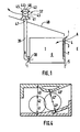
- Such an air inlet 1 is intended to be mounted in an opening 3 in a wall 4 of a building 5 for the purpose of the ventilation of the room 6 in which is this opening 3 and where therefore the air inlet opens 1.
- the wall 4 is, in the preferred embodiment envisaged, an external vertical wall, that is to say separating the interior I of the exterior E of the building 5.
- the opening 3 is formed in a window frame and is rather placed in the upper part of the room.
- the device is rather arranged so as to allow the passage of air A from the outside E towards inside I and thanks to the non-return valve, to prevent the passage of air A from the interior I towards the outside E.
- the air inlet 1 can then be qualified as an air inlet with non-return.
- the air inlet according to the invention can be the subject of other implementations for ventilation or not, of building or not, and more generally, in the circumstances where a passage of d air in one direction only is desired.
- the air inlet, according to the invention could be arranged between a part 6 and an air exhaust duct 38
- the air inlet 1 is now described in more detail, referring on the one hand to the case where it is mounted and, on the other hand for the air inlet application for buildings mentioned above. Qualifiers used such as “high”, “low”, “upper”, “lower” should be understood in context. Obviously, the air inlet 1 can be presented for sale disassembled or in separate parts.
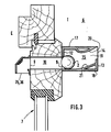
- the air inlet 1 is of the type comprising two air passage vents 8, 9 spaced transversely from one another arranged to be in communication with one another by means of a tunnel 10 of air circulation.
- An air deflector 11 is intended to be rigidly associated by one of its sides 12, with one of the two mouths - the non-return mouth 8 - and defined on another side 13, an air passage opening 14
- the device once mounted in the opening 3 is such that the two mouths 8, 9 are placed in two substantially vertical planes, the air passage opening 14 located at a higher level than that of the non-return mouth 8
- the mouth 9 can be qualified as an air intake mouth insofar as, given the desired direction of passage of air A, air A first meets the mouth 9 before the mouth 8.
- the qualifiers "non-return" or "air intake” applied to the mouths 8, 9 are essentially intended to identify the mouths relative to each other.
- the two mouths 8, 9 are either placed facing each other as shown in the figures, or offset relative to each other in the vertical and / or horizontal direction, this variant not being shown, such a structure being in known in the case of building air inlets.
- the tunnel 10 is essentially constituted by the opening 3 arranged in the wall 4 which has a certain thickness corresponding to the spacing between the two mouths 8, 9.
- This tunnel 10 is either delimited by the faces of the wall 4 resulting from the opening 3, face arranged accordingly, is materialized by a sleeve-shaped part (not shown) connecting the two mouths 8, 9, the deflector 11 and a possible deflector 16.
- This second variant has the characteristic that the device 1 forms then a unitary monobloc assembly and not two distinct assemblies as in the first variant.
- the vents 8, 9 have, in elevation, a generally rectangular shape that is strongly flattened, that is to say much longer than it is wide.
- the mouths 8, 9 are placed and arranged so that their length extends horizontally and their width vertically.
- the horizontal length can reach of the order of 25 centimeters and the vertical width can be of the order of a centimeter (for example 1.5 centimeters).
- the deflector 11 defines a longitudinal space and has two openings (respectively defined by the mouth 8 and the passage 14).
- the air inlet 1 comprises a longitudinal cylinder 2 with a horizontal axis placed in the space 5 defined by the deflector 11 and free in any direction perpendicular to its axis in this space.
- free should be understood to mean that the cylinder is not physically linked to any component of the deflector 11 and that it can move freely in any direction perpendicular to its axis.
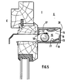
- the dimensions and the weight as well as the material of the cylinder 2 are such that the device once assembled, the cylinder 2 in isopressure configuration from the outside relative to the interior of the building, rests by gravity near the mouth non-return 8. In the overpressure configuration from the outside relative to the inside of the building, the cylinder is urged by the moving air to move away from the non-return mouth.
- a function of the cylinder 2 is to obstruct the passage of air in the unwanted direction of passage going from the passage opening 14 to the non-return mouth 8 in the overpressure configuration from the inside relative to the outside of the building. In this case, the cylinder is urged by the moving air against the non-return valve 8.
- the air flow rate passing through an air inlet is essentially an increasing function of the relative overpressure of the exterior with respect to inside the building and the air intake passage 40.
- the deflector 11 defines a longitudinal space 15 having in cross section a decreasing section from the side 12 towards the air passage opening 14. Therefore, the longitudinal space 15 can be considered to be constituted by a multitude of longitudinal elementary areas 41 which also decrease from the side 12 towards the passage opening 14.
- the cylinder defined by its height and the diameter of its bases, a constant constant master 42.
- the air passage opening 14 is located at a higher level than that of the non-return mouth. 8.
- the surface 21 on which the cylinder rests in the space 15 is inclined and grows from the non-return mouth 8 to the air passage opening 14.
- the longitudinal space 15 is defined by the side 12, by a first 17 and a second 18 longitudinal profile defining the decreasing transverse profile, the lower part of the non-return mouth 8, the passage opening of air 14 and the side 13, and by two lateral cheeks 19 parallel to one another and spaced transversely from one another, connecting the two sections 17 and 18 and the side 12 between them and defining the longitudinal limits of the space 15 , the non-return mouth 8, and the air passage opening 14.
- the sections 17 and 18 comprise a functional longitudinal wall 20, 21 defining the transverse profile of the space 15 and a second longitudinal wall so that these sections 17, 18 are tubular.
- this second longitudinal wall is produced so that the general exterior shape of the air inlet is a preferably rectangular parallelepiped, said sides 12 and 13 being opposite.
- the side 12 extends beyond the two lateral cheeks 19 so that it defines two projections having means for securing the air inlet to the opening 3 of the wall 4 of a building.
- the side 12 can also extend beyond the sections 17 and 18 so that it defines two projections having means for securing the air inlet to the opening 3.
- the longitudinal wall 21 defining the lower limit of the transverse profile of the space 15 is increasing from the non-return mouth to the air passage opening 14 according to an elliptical arc whose minor axis would belong to the plane defining the side 12. This elliptical arc is further extended by a vertical longitudinal projection defining the lower part of the air passage opening 14.
- the functional longitudinal wall 20 defining the upper limit of the transverse profile of the space 15 comprises a first part immediately adjacent to and perpendicular to the side 12 extending substantially over a third of the profile followed by a profile element of general shape in an airplane half-wing, the leading edge of which is immediately adjacent to the first part and the trailing edge constitutes the upper part of the air passage opening 14.
- the width of the non-return mouth 8 and of the air passage opening 14 is just less than the diameter of the cylinder so that once in the space 15, the cylinder 2 cannot exit through the non-return mouth or the opening 14.
- the longitudinal projection defining the lower part of the passage opening 14 serves as a stop for the cylinder 2 so that when the cylinder is in contact with said projection and with the elliptical arc, there remains a passage area d between the cylinder and the upper part of the passage opening 14.
- the cylinder 2 in isopress configuration is slightly offset from the non-return mouth by virtue of a longitudinal inclined stop 50 forming part of the functional longitudinal wall 21 on the non-return mouth side 8.
- a longitudinal inclined stop 50 forming part of the functional longitudinal wall 21 on the non-return mouth side 8.
- the profiles are made of moldable or extrudable material.
- these profiles can be made of a material having sound absorption qualities.
- the tubular profiles can also be filled with a sound absorbing material.
- the functional walls can be pierced with holes.
- the tubular profiles can advantageously be filled with a sound absorption material.
- the cylinder 2 can advantageously be made of a sound absorption material.
- the upper section 17 is associated with the air inlet in a removable manner.
- the side 12 could be provided with indexing holes, intended to cooperate with indexes arranged on the surface of the profile 17 coming into contact with the side 12.
- the profile 17 comprising a removable fastening device with the side cheeks of the air inlet, in particular a snap device. Therefore, access to the air inlet for cleaning is significantly facilitated.
- the air inlet according to the invention surprisingly constitutes a fly and mosquito repellent device, even though it does not have a protective grid. Indeed, due to small pressure variations between the outside and the inside of the building, the cylinder is almost constantly in motion in space 15. This movement plays the role of scarecrow preventing the passage of flies or mosquitoes.
- the air inlet 1 can also include a second bent deflector 16, intended to be rigidly associated by one of these ends 34 to the other of the two mouths - or inlet mouth 9 - defining, at its other end 35 an air inlet 36, so that the device 1 once mounted in the opening 3 of the wall 4, the air inlet 36 is placed in a substantially horizontal plane situated at a level lower than that of the inlet mouth 9.
- the second air deflector 16 may advantageously include a sound absorption device, for example a strip of longitudinal sound absorbing foam placed in the elbow of the second air deflector.
- the invention also relates to a ventilation installation of a building 5, by means of an air inlet as just described, being placed inside the building 5, the desired direction of passage being the one going from outside E to inside I.
- At least one such air inlet 1 is also combined with at least one air duct 39 opening into a volume of the building 5 where the air inlet opens, through a mouth 38.
- this volume is a room 6 of the building 5 comprising at least one mouth 38.
- the latter is for example located in the lower part of the room 6 opposite the device 1.
- an air extractor 37 is in communication with the mouth 38 by virtue of the duct 39 disposed in particular vertically, the extractor 37 being preferably placed on the roof 40 of the building 5.
- the air extractor 37 is of the venturi type and comprises a lower assembly 41 having a cap with frustoconical outer face with large lower base and an upper assembly 42 spaced axially from the assembly lower by spacers 43, this assembly 42 having a cap 44 and a bottom 45 with conical or frustoconical outer faces connected by their large bases 46, the conduit 39 opening into the outer space 47 between the two assemblies 41, 42.
- the mouth 38 of the duct 39 can be provided with an air inlet according to the invention.
- the desired direction of the air goes from the part 6 to the duct 39.
- the pressure differences existing between the part and the duct are much less than those existing between the exterior and interior of the building. If the requested flow is greater than the possibilities of an air intake, it is possible to associate several air inlets one on the other or one next to the other in order to obtain the flow desired.
- the air inlet could be integrated inside a PVC opening or equivalent moldable or extrudable material without departing from the scope of the present invention.
- An opening frame profile could be provided integrating into its structure the functional walls 20, 21 and the faces 13, 12, an access plate for inserting the roller, and attached cheeks for isolating the rest of the joinery from opening the air inlet without departing from the scope of the invention. The same could be expected in a frame profile.
Landscapes
- Engineering & Computer Science (AREA)
- Fluid Mechanics (AREA)
- Physics & Mathematics (AREA)
- General Engineering & Computer Science (AREA)
- Combustion & Propulsion (AREA)
- Mechanical Engineering (AREA)
- Chemical & Material Sciences (AREA)
- Ventilation (AREA)
- Road Paving Machines (AREA)
- Massaging Devices (AREA)
- Percussion Or Vibration Massage (AREA)
- Cage And Drive Apparatuses For Elevators (AREA)
- Rollers For Roller Conveyors For Transfer (AREA)
- Building Environments (AREA)
Claims (28)
- Selbstregelnder Lufteinlass ohne Rücklauf, der dazu bestimmt ist, in die Öffnung (3) einer senkrechten Wand (4) eines Gebäudes (5) zwecks Lüftung eines Raumes (6), in den er mündet, eingebaut zu werden und der in Betriebsstellung folgende Elemente umfasst:Zwei Eingänge für den Luftdurchlauf (8, 9), die querlaufend zueinander angeordnet und so eingerichtet sind, dass sie mittels eines Luftumlauftunnels (10) miteinander in Verbindung stehen.Ein Luftdeflektor (11), der dazu bestimmt ist, an einer seiner Seiten (12) mit einem der beiden Eingänge, nämlich mit dem, der den Luftrücklauf verhindert (8), fest verbunden zu werden, und der an einer anderen Seite (13) eine Öffnung zum Luftdurchlass (14) ausbildet, wobei die in die Öffnung (3) eingebaute Vorrichtung so konzipiert ist, dass die beiden Eingänge (8, 9) auf zwei etwa senkrechten Flächen angeordnet sind;Dadurch gekennzeichnet, dass der Luftdeflektor (11) einen Längsraum (15) ausbildet, in dem ein Längsachsenzylinder (2) untergebracht ist, der sich in dem Raum (15) nach allen zur Längsachse senkrechten Richtungen bewegen kann, und dessen Masse und Gewicht so ausgerechnet sind, dass bei einer Gleichdruck-Konfiguration zwischen dem Äusseren und dem Inneren des Gebäudes der Zylinder, wenn der Lufteinlass eingebaut ist, durch Schwerkraft in der Nähe des Einganges, der den Luftrücklauf verhindert (8), aufliegt, bei Verdünnung der Luft innerhalb des Gebäudes im Verhältnis zur Aussenluft, der Zylinder durch die Luftbewegung gefordert wird und sich von dem Eingang entfernt, der den Rücklauf verhindert, bei einer Konfiguration, in welcher der Luftdruck im Inneren des Gebäudes höher ist als Aussen, der Zylinder durch Schwerkraft und den inneren Überdruck so gefordert wird, dass er sich gegen den Eingang, der den Luftrücklauf verhindert, legt.
- Lufteinlass nach Anspruch 1, dadurch gekennzeichnet, dass der Längsraum (15) im Querschnitt eine Schnittlinie aufweist, die ab der zur öffnung zum Luftdurchlass (14) gerichteten Seite (12) geringer wird.
- Lufteinlass nach Anspruch 1 oder 2, dadurch gekennzeichnet, dass die Öffnung zum Luftdurchlass (14) höher als der Eingang, der den Luftrücklauf verhindert (8) angeordnet ist, so dass die Fläche (21), auf welcher der Zylinder im Raum (15) liegt, schräg ist und ab dem Eingang, der den Luftrücklauf verhindert (8) bis hin zu der öffnung zum Luftdurchlass (14) zunimmt.
- Lufteinlass nach einem der Ansprüche 1 bis 3, dadurch gekennzeichnet, dass der Längsraum (15) seitlich (12) durch ein erstes (17) und ein zweites (18) Längsprofil abgegrenzt ist, die ihrerseits das Querprofil des Längsraumes (15), den unteren Teil des Eingangs, der den Luftrücklauf verhindert (8), die Öffnung zum Luftdurchlass (14) und die Seite (13) abgrenzen; sowie durch zwei zueinander parallel verlaufende seitlich angeordnete und quer zueinander stehende Führungen (19), welche die beiden Profile (17) und (18) sowie die Seite (12) miteinander verbinden und welche die Längsgrenzen des Raums (15), des Eingangs, der den Luftrücklauf verhindert (8) und der Öffnung zum Luftdurchlass (14) abgrenzen.
- Lufteinlass nach Anspruch 4, dadurch gekennzeichnet, dass jedes der Profile (17) und (18) jeweils eine funktionelle Längswand (20), (21) aufweist, die das Querprofil des Raumes (15) abgrenzt, sowie eine zweite Längswand, so dass die Profile (17) und (18) röhrenförmig sind.
- Lufteinlass nach Anspruch 5, dadurch gekennzeichnet, dass die zweiten Längswände der Profile (17) und (18) so ausgearbeitet sind, dass die äussere Gesamtform des Lufteinlasses einem vorzugsweise rechteckigen Parallelepiped entspricht, wobei die besagten Seiten (12), (13) gegenüberliegend zueinander angeordnet sind.
- Lufteinlass nach Anspruch 5 oder 6, dadurch gekennzeichnet, dass die Seite (12) über die beiden seitlichen Führungen (19) hinaus weiterläuft, und somit zwei Vorsprünge ausbildet, die mit Befestigungsmitteln zur Verbindung des Lufteinlasses mit der öffnung (3) der Wand (4) des Gebäudes versehen sind.
- Lufteinlass nach einem der Ansprüche 5 bis 7, dadurch gekennzeichnet, dass die Seite (12) über das erste (17) und das zweite (18) Längsprofil hinaus weiterläuft, und somit zwei Vorsprünge ausbildet, die mit Befestigungsmitteln zur Verbindung des Lufteinlasses mit der Öffnung (3) der Wand (4) des Gebäudes versehen sind.
- Lufteinlass nach einem der Ansprüche 1 bis 8, dadurch gekennzeichnet, dass die funktionelle Längswand (21), welche die innere Grenze des Querprofils des Raumes (15) ausbildet, von dem Eingang, der den Luftrücklauf verhindert bis hin zur Öffnung zum Luftdurchlass (14) zunimmt, und zwar einem Stelzbogen entsprechend, dessen kleine Achse zu der Fläche gehört, welche die Seite (12) abgrenzt, und wobei der Stelzbogen ausserdem auf der Seite der Öffnung zum Luftdurchlass (14) durch einen senkrechten Längsvorsprung verlängert wird, der das Unterteil der Öffnung zum Luftdurchlass (14) ausbildet.
- Lufteinlass nach Anspruch 9, dadurch gekennzeichnet, dass die besagte funktionelle Längswand (21) auf der Seite des Eingangs, der den Luftrücklauf verhindert, einen schräggestellten Längsanschlag (50) aufweist, der von der unteren Kante des Eingangs, der den Luftrücklauf verhindert, bis zu dem Stelzbogen abnimmt, so dass sich der Zylinder (2) bei Gleichdruck in der Nähe des Eingangs, der den Luftrücklauf verhindert (8), befindet, und wobei er dennoch zwischen seiner Peripherie und dem oberen Rand des Eingangs, der den Luftrücklauf verhindert (8), eine Fläche für den Luftdurchlauf freilässt.
- Lufteinlass nach einem der Ansprüche 1 bis 10, dadurch gekennzeichnet, dass die funktionelle Längswand (20), welche das obere Teil des Querprofils des Raumes (15) ausbildet, ein unmittelbar an die Seite (12) und dazu senkrecht verlaufendes erstes Teil umfasst, das sich ungefähr auf einem Drittel des Profils erstreckt, das durch ein Profilelement in Form einer halben Flugzeugtragfläche verlängert wird, dessen Stirnkante unmittelbar an das erste Teil anstösst und dessen Unterkante das obere Teil der Öffnung zum Luftdurchlass (14) ausbildet.
- Lufteinlass nach einem der Ansprüche 3 bis 10, dadurch gekennzeichnet, dass die Breite des Eingangs, der den Luftrücklauf verhindert (14) knapp unter dem Wert des Zylinderdurchmessers liegt, so dass der im Raum (15) liegende Zylinder nicht durch den Eingang, der den Luftrücklauf verhindert oder durch die Öffnung zum Luftdurchlass (14) austreten kann.
- Lufteinlass nach einem der Ansprüche 9 bis 12, dadurch gekennzeichnet, dass der Längsvorsprung, der das Unterteil der Öffnung zum Luftdurchlass (14) ausbildet, dem Zylinder (2) als Anschlag dient, und zwar so, dass, wenn der Zylinder (2) mit besagtem Vorsprung und dem Stelzbogen in Berührung ist, eine Fläche zum Luftdurchlass zwischen dem Zylinder und dem oberen Teil der Öffnung zum Luftdurchlass bestehen bleibt.
- Lufteinlass nach einem der Ansprüche 4 bis 13, dadurch gekennzeichnet, dass das erste (17) und das zweite (18) Profil aus einem Material besteht, das formbar ist oder stranggepresst werden kann.
- Lufteinlass nach einem der Ansprüche 4 bis 14, dadurch gekennzeichnet, dass das erste und das zweite Profil aus einem geräuschhemmenden Material hergestellt sind.
- Lufteinlass nach einem der Ansprüche 4 bis 14, dadurch gekennzeichnet, dass das erste (17) und das zweite (18) röhrenförmige Profil mit einem geräuschhemmenden Material ausgefüllt sind.
- Lufteinlass nach einem der Ansprüche 5 bis 16, dadurch gekennzeichnet, dass die funktionellen Längswände (20, 21) vielfach gelocht sind, um die Geräuschhemmung zu erhöhen.
- Lufteinlass nach einem der Ansprüche 1 bis 17, dadurch gekennzeichnet, dass der Zylinder aus einem geräuschhemmenden Material hergestellt ist.
- Lufteinlass nach einem der Ansprüche 1 bis 18, dadurch gekennzeichnet, dass er ausserdem mit einem zweiten bogenförmigen Luftdeflektor (16) versehen ist, der dazu bestimmt ist, an einem seiner Enden (34) mit dem anderen der beiden Eingänge, oder dem Eingang für den Luftdurchlauf (9), fest verbunden zu werden, wobei er an seinem anderen Ende (35) eine Fläche (36) für den Luftdurchlass ausbildet, so dass sich, wenn der Lufteinlass in die öffnung (3) der Wand (4) eingebaut ist, die Fläche für den Luftdurchlass (36) auf einer etwa waagerechten Ebene befindet, die niedriger als die des Eingangs für den Luftdurchlauf (9) liegt.
- Lufteinlass nach einem der Ansprüche 1 bis 19, dadurch gekennzeichnet, dass er ausserdem eine Buchse aufweist, welche die beiden Eingänge (8, 9) und gegebenenfalls die beiden Deflektoren (11, 16) miteinander verbindet.
- Lufteinlass nach einem der Ansprüche 18 bis 20, dadurch gekennzeichnet, dass der zweite bogenförmige Luftdeflektor mit einer geräuschhemmenden Vorrichtung versehen ist.
- Lufteinlass entprechend Anspruch 21, dadurch gekennzeichnet, dass die geräuschhemmende Vorrichtung aus einem Längsstreifen aus Kunstharzschaum besteht, der in der Krümmung des zweiten Luftdeflektors angebracht ist.
- Lufteinlass nach einem der Ansprüche 18 bis 22, dadurch gekennzeichnet, dass der zweite Luftdeflektor aus einem formbaren Material hergestellt ist.
- Lufteinlass nach einem der Ansprüche 18 bis 23, dadurch gekennzeichnet, dass der zweite Luftdeflektor aus einem geräuschhemmenden Material hergestellt ist.
- Ventilationsanlage eines Gebäudes (5) mittels wenigstens eines Lufteinlasses (1), dadurch gekennzeichnet, dass der Lufteinlass einem der Ansprüche 1 bis 24 entspricht, wobei der Deflektor (11), der den Zylinder übernimmt, im Innern I des Gebäudes (5) und aufsteigend angeordnet ist, und wobei die gewünschte Durchlaufrichtung von Aussen E nach Innen I geht.
- Anlage nach Anspruch 25, dadurch gekennzeichnet, dass mindestens ein Luftschacht (38), der in einen Raum des Gebäudes (5) münde , wo auch der Lufteinlass (1) mündet, mit mindestens einem Lufteinlass (1) kombiniert ist.
- Anlage nach Anspruch 26, dadurch gekennzeichnet, dass dem Luftschacht (38) ein Luftabsauger (37) auf dem Dach des Gebäudes (5) beigeordnet ist, der in Verbindung mit der Leitung (39) steht, die mittels des Luftschachtes (38) in den Raum (6) des Gebäudes (5) mündet.
- Anlage nach Anspruch 27, dadurch gekennzeichnet, dass der Schacht (38) mindestens mit einem Lufteinlass (1) versehen ist, wobei die gewünschte Richtung der Luft vom Raum (6) zur Leitung (39) geht.
Applications Claiming Priority (2)
| Application Number | Priority Date | Filing Date | Title |
|---|---|---|---|
| FR9314473A FR2713318B1 (fr) | 1993-12-02 | 1993-12-02 | Entrée d'air autoréglable, antiretour, acoustique à rouleau; installation comprenant une telle entrée d'air. |
| FR9314473 | 1993-12-02 |
Publications (2)
| Publication Number | Publication Date |
|---|---|
| EP0656513A1 EP0656513A1 (de) | 1995-06-07 |
| EP0656513B1 true EP0656513B1 (de) | 1997-10-08 |
Family
ID=9453495
Family Applications (1)
| Application Number | Title | Priority Date | Filing Date |
|---|---|---|---|
| EP94402748A Expired - Lifetime EP0656513B1 (de) | 1993-12-02 | 1994-11-30 | Selbstregelnder, rückstromsperrender Lufteinlass versehen mit einer akustischen Rolle, Installation versehen mit einem derartigen Lufteinlass |
Country Status (5)
| Country | Link |
|---|---|
| EP (1) | EP0656513B1 (de) |
| AT (1) | ATE159094T1 (de) |
| DE (1) | DE69406093T2 (de) |
| ES (1) | ES2113067T3 (de) |
| FR (1) | FR2713318B1 (de) |
Cited By (1)
| Publication number | Priority date | Publication date | Assignee | Title |
|---|---|---|---|---|
| EP1005621A1 (de) | 1997-08-18 | 2000-06-07 | MFZ GBR Moderne Fenster Zubehör | Belüftungseinrichtung für fensterelemente |
Families Citing this family (4)
| Publication number | Priority date | Publication date | Assignee | Title |
|---|---|---|---|---|
| FR2749930B1 (fr) * | 1996-06-18 | 1998-09-04 | Amphoux Andre | Bouche d'extraction pour la ventilation d'une piece et systeme statique ou statomecanique incluant une telle bouche |
| DE102008040462B4 (de) * | 2008-07-16 | 2013-09-12 | Sommer Metallbau-Stahlbau Gmbh & Co. Kg | Druckstoßklappe |
| DE102013114250A1 (de) * | 2013-12-17 | 2015-07-02 | Maco Technologie Gmbh | Falzlüfter |
| CN110081519B (zh) * | 2019-04-29 | 2023-07-14 | 珠海格力电器股份有限公司 | 新风装置、空调室内机及新风装置控制方法 |
Family Cites Families (3)
| Publication number | Priority date | Publication date | Assignee | Title |
|---|---|---|---|---|
| FR2105313A5 (de) * | 1970-08-13 | 1972-04-28 | Ogny Jean D | |
| FR2244964A1 (en) * | 1973-09-20 | 1975-04-18 | Applimo | Constant flow ventilation duct - has rolling body moved by air pressure towards reduced section of duct |
| FR2652883B1 (fr) * | 1989-10-06 | 1994-02-11 | Andre Amphoux | Dispositif pour le passage d'air avec systeme antirefoulant, et installation comportant un tel dispositif. |
-
1993
- 1993-12-02 FR FR9314473A patent/FR2713318B1/fr not_active Expired - Lifetime
-
1994
- 1994-11-30 ES ES94402748T patent/ES2113067T3/es not_active Expired - Lifetime
- 1994-11-30 EP EP94402748A patent/EP0656513B1/de not_active Expired - Lifetime
- 1994-11-30 DE DE69406093T patent/DE69406093T2/de not_active Expired - Fee Related
- 1994-11-30 AT AT94402748T patent/ATE159094T1/de not_active IP Right Cessation
Cited By (1)
| Publication number | Priority date | Publication date | Assignee | Title |
|---|---|---|---|---|
| EP1005621A1 (de) | 1997-08-18 | 2000-06-07 | MFZ GBR Moderne Fenster Zubehör | Belüftungseinrichtung für fensterelemente |
Also Published As
| Publication number | Publication date |
|---|---|
| EP0656513A1 (de) | 1995-06-07 |
| FR2713318A1 (fr) | 1995-06-09 |
| DE69406093D1 (de) | 1997-11-13 |
| FR2713318B1 (fr) | 1996-02-16 |
| ATE159094T1 (de) | 1997-10-15 |
| ES2113067T3 (es) | 1998-04-16 |
| DE69406093T2 (de) | 1998-05-14 |
Similar Documents
| Publication | Publication Date | Title |
|---|---|---|
| EP0641972B1 (de) | Statische, dynamische Gasabfuhreinrichtung | |
| EP0656513A1 (de) | Selbstregelnder, rückstromsperrender Lufteinlass versehen mit einer akustischen Rolle, Installation versehen mit einem derartigen Lufteinlass | |
| FR2540916A1 (fr) | Element d'aeration pour couverture de batiment | |
| WO2012020193A1 (fr) | Ensemble de pompe à chaleur et procédé de montage d'un tel ensemble de pompe à chaleur dans un bâti | |
| EP1947384A1 (de) | Mechanische Hilfsvorrichtung für die Ableitung von Gasflüssen, insbesondere für Wohneinheiten | |
| EP0421841A1 (de) | Einrichtung zur Luftführung und Anlage, die eine derartige Einrichtung enthält | |
| EP0643192B1 (de) | Rolladenkasten | |
| FR2916518A1 (fr) | Groupe d'extraction d'air hors d'un batiment et installation de desenfumage d'un batiment | |
| FR2873400A1 (fr) | Ensemble de lames articulees, tablier de volet roulant et volet roulant ainsi forme | |
| EP3302038B1 (de) | Vorrichtung zum diffundieren von luft in einem raum eines gebäudes, insbesondere einem brutraum | |
| FR2855842A1 (fr) | Exutoire de fumees a haute performance aeraulique, specifiquement adapte pour des voutes de toitures de constructions ou de batiments | |
| EP1026359B1 (de) | Dichtung für Rolladenkasten | |
| FR3095031A1 (fr) | Bouche d’extraction d’air | |
| EP1700993B1 (de) | Belüfteter Fenster, Fenstertür oder dergleiche, mit einer Fluidverbindung eines Luftspaltes mit der Aussenumgebung durch eine Aussenglasscheibe und eine diese Scheibe haltende Leiste | |
| EP0814307A1 (de) | Entlüftungsauslass zur Belüftung eines Raumes | |
| FR2866372A1 (fr) | Exutoire de desenfumage comportant des moyens de canalisation d'une partie de la fumee | |
| FR2805032A1 (fr) | Dispositif de regulation automatique du debit d'air pour la ventilation d'un local | |
| EP0965723B1 (de) | Rolladen für Tür, Fenster oder dergleichen | |
| EP0621452A1 (de) | Vorrichtung zur automatischen Luftmengenregelung in einer Lüftungsanlage, Klimaanlage oder dergleichen | |
| FR2740818A1 (fr) | Perfectionnements aux dispositifs d'assourdissement d'un passage d'air d'une menuiserie | |
| FR3037383A1 (fr) | Dispositif de desenfumage | |
| FR2803869A1 (fr) | Dispositif "pare-tempete" pour l'evacuation des eaux de ruissellement et de condensation d'un chassis d'une huisserie exterieure | |
| EP1398567A2 (de) | Schornsteinaufsatz zur Rauchgasabsaugung | |
| FR2740865A1 (fr) | Bouche d'entree d'air autoreglable a obturateur en equerre pour installation de ventilation | |
| EP3885524A1 (de) | Anschlagvorrichtung für rollladen |
Legal Events
| Date | Code | Title | Description |
|---|---|---|---|
| PUAI | Public reference made under article 153(3) epc to a published international application that has entered the european phase |
Free format text: ORIGINAL CODE: 0009012 |
|
| AK | Designated contracting states |
Kind code of ref document: A1 Designated state(s): AT BE CH DE ES GB IT LI NL |
|
| 17P | Request for examination filed |
Effective date: 19950706 |
|
| GRAG | Despatch of communication of intention to grant |
Free format text: ORIGINAL CODE: EPIDOS AGRA |
|
| 17Q | First examination report despatched |
Effective date: 19970224 |
|
| GRAH | Despatch of communication of intention to grant a patent |
Free format text: ORIGINAL CODE: EPIDOS IGRA |
|
| GRAH | Despatch of communication of intention to grant a patent |
Free format text: ORIGINAL CODE: EPIDOS IGRA |
|
| GRAA | (expected) grant |
Free format text: ORIGINAL CODE: 0009210 |
|
| AK | Designated contracting states |
Kind code of ref document: B1 Designated state(s): AT BE CH DE ES GB IT LI NL |
|
| REF | Corresponds to: |
Ref document number: 159094 Country of ref document: AT Date of ref document: 19971015 Kind code of ref document: T |
|
| REG | Reference to a national code |
Ref country code: CH Ref legal event code: EP |
|
| REF | Corresponds to: |
Ref document number: 69406093 Country of ref document: DE Date of ref document: 19971113 |
|
| ITF | It: translation for a ep patent filed | ||
| REG | Reference to a national code |
Ref country code: CH Ref legal event code: NV Representative=s name: BOVARD AG PATENTANWAELTE |
|
| GBT | Gb: translation of ep patent filed (gb section 77(6)(a)/1977) |
Effective date: 19980109 |
|
| REG | Reference to a national code |
Ref country code: ES Ref legal event code: FG2A Ref document number: 2113067 Country of ref document: ES Kind code of ref document: T3 |
|
| PLBE | No opposition filed within time limit |
Free format text: ORIGINAL CODE: 0009261 |
|
| STAA | Information on the status of an ep patent application or granted ep patent |
Free format text: STATUS: NO OPPOSITION FILED WITHIN TIME LIMIT |
|
| 26N | No opposition filed | ||
| REG | Reference to a national code |
Ref country code: GB Ref legal event code: IF02 |
|
| PGFP | Annual fee paid to national office [announced via postgrant information from national office to epo] |
Ref country code: NL Payment date: 20031105 Year of fee payment: 10 |
|
| PGFP | Annual fee paid to national office [announced via postgrant information from national office to epo] |
Ref country code: AT Payment date: 20031112 Year of fee payment: 10 |
|
| PGFP | Annual fee paid to national office [announced via postgrant information from national office to epo] |
Ref country code: GB Payment date: 20031126 Year of fee payment: 10 |
|
| PGFP | Annual fee paid to national office [announced via postgrant information from national office to epo] |
Ref country code: CH Payment date: 20031128 Year of fee payment: 10 |
|
| PGFP | Annual fee paid to national office [announced via postgrant information from national office to epo] |
Ref country code: ES Payment date: 20031209 Year of fee payment: 10 |
|
| PG25 | Lapsed in a contracting state [announced via postgrant information from national office to epo] |
Ref country code: LI Free format text: LAPSE BECAUSE OF NON-PAYMENT OF DUE FEES Effective date: 20041130 Ref country code: GB Free format text: LAPSE BECAUSE OF NON-PAYMENT OF DUE FEES Effective date: 20041130 Ref country code: CH Free format text: LAPSE BECAUSE OF NON-PAYMENT OF DUE FEES Effective date: 20041130 Ref country code: AT Free format text: LAPSE BECAUSE OF NON-PAYMENT OF DUE FEES Effective date: 20041130 |
|
| PG25 | Lapsed in a contracting state [announced via postgrant information from national office to epo] |
Ref country code: ES Free format text: LAPSE BECAUSE OF NON-PAYMENT OF DUE FEES Effective date: 20041201 |
|
| PGFP | Annual fee paid to national office [announced via postgrant information from national office to epo] |
Ref country code: BE Payment date: 20050215 Year of fee payment: 11 |
|
| PG25 | Lapsed in a contracting state [announced via postgrant information from national office to epo] |
Ref country code: NL Free format text: LAPSE BECAUSE OF NON-PAYMENT OF DUE FEES Effective date: 20050601 |
|
| REG | Reference to a national code |
Ref country code: CH Ref legal event code: PL |
|
| GBPC | Gb: european patent ceased through non-payment of renewal fee |
Effective date: 20041130 |
|
| NLV4 | Nl: lapsed or anulled due to non-payment of the annual fee |
Effective date: 20050601 |
|
| PG25 | Lapsed in a contracting state [announced via postgrant information from national office to epo] |
Ref country code: IT Free format text: LAPSE BECAUSE OF NON-PAYMENT OF DUE FEES;WARNING: LAPSES OF ITALIAN PATENTS WITH EFFECTIVE DATE BEFORE 2007 MAY HAVE OCCURRED AT ANY TIME BEFORE 2007. THE CORRECT EFFECTIVE DATE MAY BE DIFFERENT FROM THE ONE RECORDED. Effective date: 20051130 Ref country code: BE Free format text: LAPSE BECAUSE OF NON-PAYMENT OF DUE FEES Effective date: 20051130 |
|
| REG | Reference to a national code |
Ref country code: ES Ref legal event code: FD2A Effective date: 20041201 |
|
| BERE | Be: lapsed |
Owner name: *AMPHOUX ANDRE Effective date: 20051130 |
|
| PGFP | Annual fee paid to national office [announced via postgrant information from national office to epo] |
Ref country code: DE Payment date: 20081127 Year of fee payment: 15 |
|
| PG25 | Lapsed in a contracting state [announced via postgrant information from national office to epo] |
Ref country code: DE Free format text: LAPSE BECAUSE OF NON-PAYMENT OF DUE FEES Effective date: 20100601 |