EP0656523B1 - Vorrichtung zur meridionalen Abtastung von Kugeloberflächen - Google Patents
Vorrichtung zur meridionalen Abtastung von Kugeloberflächen Download PDFInfo
- Publication number
- EP0656523B1 EP0656523B1 EP94118547A EP94118547A EP0656523B1 EP 0656523 B1 EP0656523 B1 EP 0656523B1 EP 94118547 A EP94118547 A EP 94118547A EP 94118547 A EP94118547 A EP 94118547A EP 0656523 B1 EP0656523 B1 EP 0656523B1
- Authority
- EP
- European Patent Office
- Prior art keywords
- sphere
- cylinder
- rollers
- fact
- ball
- Prior art date
- Legal status (The legal status is an assumption and is not a legal conclusion. Google has not performed a legal analysis and makes no representation as to the accuracy of the status listed.)
- Expired - Lifetime
Links
- 230000033001 locomotion Effects 0.000 claims description 22
- 238000000034 method Methods 0.000 claims description 4
- 230000008569 process Effects 0.000 claims description 4
- 230000005540 biological transmission Effects 0.000 claims description 3
- 230000008878 coupling Effects 0.000 claims description 2
- 238000010168 coupling process Methods 0.000 claims description 2
- 238000005859 coupling reaction Methods 0.000 claims description 2
- 238000011144 upstream manufacturing Methods 0.000 claims description 2
- 230000001360 synchronised effect Effects 0.000 claims 1
- 238000004519 manufacturing process Methods 0.000 description 6
- 230000008859 change Effects 0.000 description 3
- 238000005096 rolling process Methods 0.000 description 3
- 230000008901 benefit Effects 0.000 description 2
- 238000001514 detection method Methods 0.000 description 2
- 230000007246 mechanism Effects 0.000 description 2
- 230000003287 optical effect Effects 0.000 description 2
- 239000000523 sample Substances 0.000 description 2
- 238000012360 testing method Methods 0.000 description 2
- 241000237942 Conidae Species 0.000 description 1
- 229910000831 Steel Inorganic materials 0.000 description 1
- 230000000712 assembly Effects 0.000 description 1
- 238000000429 assembly Methods 0.000 description 1
- 230000015572 biosynthetic process Effects 0.000 description 1
- 239000000969 carrier Substances 0.000 description 1
- 230000007547 defect Effects 0.000 description 1
- 238000010586 diagram Methods 0.000 description 1
- 238000004049 embossing Methods 0.000 description 1
- 238000005516 engineering process Methods 0.000 description 1
- 230000002349 favourable effect Effects 0.000 description 1
- 230000000977 initiatory effect Effects 0.000 description 1
- 239000007788 liquid Substances 0.000 description 1
- 239000002184 metal Substances 0.000 description 1
- 230000010363 phase shift Effects 0.000 description 1
- 230000002028 premature Effects 0.000 description 1
- 238000003825 pressing Methods 0.000 description 1
- 230000011514 reflex Effects 0.000 description 1
- 238000000926 separation method Methods 0.000 description 1
- 239000010959 steel Substances 0.000 description 1
Images

Classifications
-
- G—PHYSICS
- G01—MEASURING; TESTING
- G01B—MEASURING LENGTH, THICKNESS OR SIMILAR LINEAR DIMENSIONS; MEASURING ANGLES; MEASURING AREAS; MEASURING IRREGULARITIES OF SURFACES OR CONTOURS
- G01B5/00—Measuring arrangements characterised by the use of mechanical techniques
- G01B5/28—Measuring arrangements characterised by the use of mechanical techniques for measuring roughness or irregularity of surfaces
Definitions
- the invention relates to a device for the most complete scanning possible of spherical surfaces through meridional Rotary movement of the ball with a fixed arrangement of a probe, sensor or the like.
- Corresponding tasks exist, for example, in the field of test technology to control the Quality of steel balls e.g. for cracks, geometry or surface defects as well as at the Laser hardening of the near-surface edge zone of special balls or when embossing (baking) of information carriers in spherical surfaces.
- a device in which the ball to be scanned is guided by a control roller and a support roller, and is continuously driven by a friction roller, the axis of rotation of the ball with respect to an imaginary marking on the ball surface being influenced by the Control roller changes slightly from revolution to revolution (meridional rotation of the ball), so that finally the entire surface of the ball at a fixed point on the z.
- a sensor is arranged, is moved past.
- the specifically adapted geometry of the control roller is of crucial importance. This consists of two opposing, rigidly connected cones, the cone angle of which changes sinusoidally and fluctuates symmetrically by the value of 45 degrees, one revolution of the cone shell corresponding to one sine period.
- the ball is clamped between the friction roller, support roller and control roller under consideration of defined angular relationships and forced to rotate via frictional contact.
- This control roller represents a complicated precision part with extreme demands on the manufacturing accuracy. Its production is very complex and cost-intensive. In addition, this control roller is a pronounced wear part, since sliding friction (sliding friction) also occurs at the same time as rolling friction, which leads to premature wear even with the use of hard metal and thus errors in scanning and very quickly to complete failure (maximum running time 200 hours).
- the geometrical boundary conditions for ball mounting and guiding result in an unfavorable accessibility to the ball surface, so that there are restrictions with regard to the number of sensors. They also have to be swung to the side with each ball change, which makes it difficult to process larger quantities of balls per unit of time.
- U.S. Patent 5,223,793 provides a general overview of a number of principal Possibilities for generating the desired meridional movement are listed as well as some methematic-physical connections between initiation of movement and lane formation derived from the spherical surface. It is shown that if the ideal conditions are not met (see u.) more or less large surface areas of the ball are not scanned.
- the object of the invention is the meridional ball movement by means of a the above. disadvantage avoiding device by a new design of the coupling of the meridional movement to reach.
- the track width and thus the scanning density can be made variable by appropriate lever design, for example by means of a variable lever length by means of an adjustable articulation point.
- This enables the device according to the invention to be easily adapted to changing tasks.
- a variation of the scanning track is not possible with the control roller according to the CS-PS. Due to the separation of functions between the ball holder and the control mechanism, miniaturization of the mechanism is also possible, whereby balls with a diameter of far less than 3 mm can be examined. This is supported by the fact that a larger surface area of the ball remains free from component overlaps and the accessibility is thus also significantly improved for relatively large sensors (1: 1.5).
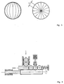
- the axes of these control cylinder rollers are mounted in forks G which can be moved about the control axes a1, a2.
- a symmetrical pendulum movement with the amplitude angle Beta (0 ° ⁇ Beta ⁇ Beta max , with Beta max approx. 10 ° ... 20 °) takes place around one or both of these axes a1, a2 as a steering movement, exactly in synchronization with the ball rotation. If both roles are steered, the steering movement takes place in opposite phase to each other, i.e. with a phase shift of 180 degrees.
- the steering movement is coupled to the controlled rollers R, for example by lever H with the pendulum angle gamma on the extended axles of these rollers, the levers being, for example, by eccentric E1, E2, realized by eccentrically mounted ball bearings with a fixed outer ring, or cams on the axle of the drive cylinder Z are set in motion.
- the eccentrics or cams are scanned, for example, by means of set screws S, and the levers can be returned by springs with a base on a fixed base plate or by a tension spring which is arranged between the levers H or between the extended axes of the controlled rollers.
- the track width s is the maximum distance between two adjacent tracks or taxiways at equatorial height. This track width is determined by the pendulum angle beta.
- an eddy current sensor for crack detection and an optical sensor for recording the optical surface quality based on the reflex principle perform a contact-free scanning of the surface, the track width s of the meridional movement being smaller than the smaller one the detection widths (visible width) of the sensors is set.
- Fig. 3 an embodiment variant of the invention is shown as e.g. in automated Manufacturing or testing systems can be used.
- the ones for the ball holder required stops by balls upstream or downstream in the technological process the same size as the ball to be scanned.
- the balls are changed by cyclical Continue pushing new balls using z. B. piston from a feed channel in the Measuring position along a parallel to the drive cylinder axis. That way, the already measured ball used as a stop for the ball to be measured subsequently, the on it The following serves as a second stop, so that automation of the ball change becomes possible.
- the balls become suitable when moving along the cylinder axis Scenes or limits performed, so that the movement sequence described forcibly comes about.
Landscapes
- Physics & Mathematics (AREA)
- General Physics & Mathematics (AREA)
- Investigating Or Analyzing Materials By The Use Of Ultrasonic Waves (AREA)
- Transmission Devices (AREA)
- Investigating Materials By The Use Of Optical Means Adapted For Particular Applications (AREA)
- Testing Of Devices, Machine Parts, Or Other Structures Thereof (AREA)
- Rolling Contact Bearings (AREA)
- Friction Gearing (AREA)
Description
Diese Steuerrolle stellt ein kompliziertes Präzisionsteil mit extremen Anforderungen an die Fertigungsgenauigkeit dar. Ihre Fertigung ist sehr aufwendig und kostenintensiv. Darüber hinaus ist diese Steuerrolle ein ausgesprochenes Verschleißteil, da gleichzeitig zur Rollreibung auch Gleitreibung (Bohrreibung) auftritt, was selbst bei Verwendung von Hartmetall zu frühzeitigem Verschleiß und damit Fehlern bei der Abtastung und recht schnell zum völligen Ausfall führt (Laufzeit maximal 200 Stunden).
Die geometrischen Randbedingungen zur Kugelhalterung und -führung ergeben eine ungünstige Zugänglichkeit zur Kugeloberfläche, so daß Einschränkungen bezüglich der Anzahl von Sensoren bestehen. Diese müssen außerdem bei jedem Kugelwechsel zur Seite geschwenkt werden, was den technologischen Durchlauf größerer Kugelmengen pro Zeiteinheit erschwert.
Da die erfindungsgemäße Kugelsteuerung auf der Anwendung reiner Rollreibung zwischen Kugeloberfläche und Antriebszylinder sowie den Steuer-Zylinderrollen basiert, wird ein Verschleiß weitgehend vermieden. Ein weiterer Vorteil des neuen Verfahrens liegt in der Möglichkeit, einen Kugelwechsel relativ einfach zu automatisieren. Dabei ist es besonders günstig, daß die Sensoren an Ort und Stelle (Meßposition) verbleiben können. Die geometrisch günstige Gestaltung erlaubt dabei sogar die gleichzeitige Anordnung mehrerer Sensoren bzw. Tastköpfe zur Ermittlung verschiedener Oberflächenkennwerte der zu untersuchenden Kugel.
Die Spurbreite und damit die Abtastdichte läßt sich durch entsprechende Hebelgestaltung z.B. mittels veränderlicher Hebellänge durch einstellbaren Anlenkungspunkt variabel ausführen. Dies ermöglicht die einfache Anpassung der erfindungsgemäßen Vorrichtung an veränderliche Aufgabenstellungen. Mit der Steuerrolle nach der CS-PS ist eine Variation der Abtastspur nicht möglich.
Aufgrund der Funktionstrennung von Kugelhalterung und Steuermechanik ist insbesondere auch eine Miniaturisierung der Mechanik möglich, wobei Kugeln mit weit unter 3 mm Durchmesser untersucht werden können. Dies wird dadurch unterstützt, daß ein größerer Oberflächenbereich der Kugel von Bauelementeüberdeckungen freibleibt und sich damit die Zugänglichkeit auch für relativ große Sensoren wesentlich verbessert (1:1,5).
Um z.B. eine lückelose Erfassung von Qualitätsmerkmalen auf der Kugeloberfläche sowie dicht darunter vorzunehmen, wird durch einen Wirbelstromsensor zur Rißerkennung und einen optischen Sensor zur Erfassung der optischen Oberflächengüte nach dem Reflexprinzip eine berührungsfreie Abtastung der Oberfläche durchgeführt, wobei die Spurbreite s der Meridionalbewegung geringer als die kleinere der Erfassungsbreiten (Sichtbreite) der Sensoren eingestellt wird.
Claims (5)
- Vorrichtung zur meridionalen Abtastung von Kugeloberflächen bei der die mit Hilfe eines Sensors abzutastende Kugel (K) von einem rotierenden Zylinder (Z) im Reibkontakt angetrieben wird und in Längsrichtung dieses Zylinders (Z) durch zwei Anschläge (A), in Querrichtung durch zwei Zylinderrollen, gehaltert ist, und bei der zusätzliche Steuereinrichtungen (E1,E2,S,H) vorgesehen sind, mittels derer die Kugel (K) mit einer zweiten, senkrecht auf der Achse der Antriebsbewegung stehenden Drehbewegung überlagert wird,
dadurch gekennzeichnet, daß zur Vermittlung dieser zweiten Drehbewegung zwei auf der Kugeloberfläche mitlaufende Steuerzylinderrollen (R) unter einem Winkel Alpha symmetrisch zur Verbindungslinie Kugelmitte - Antriebszylinderachse angeordnet sind, wobei Alpha zwischen 0 und 90° beträgt und in einer Ebene senkrecht zur Rotationsachse des Zylinders (Z) liegt, und wobei mindestens eine der Steuerzylinderrollen (R) lenkbar um die durch den Winkel Alpha vorgegebene Lenkachse (a1,a2) ausgeführt ist, und eine Lenkbewegung mit dem Amplitudenwinkel Beta zwischen 0 und 20° genau synchron mit dem Kugelantrieb eingekoppelt ist und daß mindestens ein Sensor eingesetzt ist. - Vorrichtung nach Anspruch 1, dadurch gekennzeichnet, daß beide Steuerzylinderrollen (R) lenkbar angeordnet sind und ihre Lenkbewegung zueinander mit einer Phasenverschiebung von 180 Grad in Gegenphase erfolgt.
- Vorrichtung nach Anspruch 1, dadurch gekennzeichnet, daß die Einkopplung der Lenkbewegung auf die Steuerzylinderrollen (R) durch Hebel (H) mit dem Pendelwinkel Gamma zwischen 0 und 30° auf die verlängerten Achsen dieser Steuerzylinderrollen (R) erfolgt, wobei die Hebel (H) direkt durch mit dem Zylinder (Z) verbundene Auslenkeinrichtungen bewegt werden.
- Vorrichtung nach Anspruch 1, dadurch gekennzeichnet, daß Mittel vorgesehen sind mittels derer die Steuerzylinderrollen (R) elastisch auf die Oberfläche der Kugel (K) gedrückt werden.
- Vorrichtung nach Anspruch 1, dadurch gekennzeichnet, daß die Anschläge (A) zur Kugelhalterung durch im technologischen Ablauf vor- bzw. nachgelagerte Kugeln der gleichen Größe gebildet werden.
Applications Claiming Priority (2)
| Application Number | Priority Date | Filing Date | Title |
|---|---|---|---|
| DE4341198A DE4341198A1 (de) | 1993-12-03 | 1993-12-03 | Vorrichtung zur meridionalen Abtastung von Kugeloberflächen |
| DE4341198 | 1993-12-03 |
Publications (3)
| Publication Number | Publication Date |
|---|---|
| EP0656523A2 EP0656523A2 (de) | 1995-06-07 |
| EP0656523A3 EP0656523A3 (de) | 1996-01-03 |
| EP0656523B1 true EP0656523B1 (de) | 1998-07-22 |
Family
ID=6504075
Family Applications (1)
| Application Number | Title | Priority Date | Filing Date |
|---|---|---|---|
| EP94118547A Expired - Lifetime EP0656523B1 (de) | 1993-12-03 | 1994-11-25 | Vorrichtung zur meridionalen Abtastung von Kugeloberflächen |
Country Status (4)
| Country | Link |
|---|---|
| EP (1) | EP0656523B1 (de) |
| CZ (1) | CZ285267B6 (de) |
| DE (2) | DE4341198A1 (de) |
| ES (1) | ES2119948T3 (de) |
Families Citing this family (3)
| Publication number | Priority date | Publication date | Assignee | Title |
|---|---|---|---|---|
| DE10235964B3 (de) * | 2002-08-06 | 2004-04-08 | H. C. Starck Ceramics Gmbh & Co. Kg | Vorrichtung und Verfahren zur visuellen Kontrolle von Kugeln |
| CN102507872B (zh) * | 2011-11-04 | 2014-06-11 | 哈尔滨工程大学 | 一种基于等效周长的球面缺陷扫描方法 |
| CN111896628B (zh) * | 2020-06-30 | 2023-08-04 | 洛阳轴承研究所有限公司 | 一种氮化硅陶瓷球超声波无损检测方法 |
Family Cites Families (11)
| Publication number | Priority date | Publication date | Assignee | Title |
|---|---|---|---|---|
| CS123081A (de) * | ||||
| US3361961A (en) * | 1964-10-27 | 1968-01-02 | United States Steel Corp | Probe supporting apparatus with pivotably adjustable legs |
| US3398592A (en) * | 1964-12-01 | 1968-08-27 | Vyzk Ustav Stroj Tech | Arrangement for the control of the movement of balls |
| DE1573840B1 (de) * | 1966-12-24 | 1970-07-16 | Skf Kugellagerfabriken Gmbh | Antriebsvorrichtung fuer in einer Pruefeinrichtung zu pruefende Kugeln |
| DE2106891B2 (de) * | 1971-02-13 | 1972-11-30 | SKF Kugellagerfabnken GmbH, 8720 Schweinfurt | Antriebsvorrichtung fuer kugeln zu deren zerstoerungsfreien pruefung |
| US4155455A (en) * | 1977-09-06 | 1979-05-22 | Magnetic Analysis Corporation | Eddy current and variable reluctance test apparatus for rollers and the like |
| US4430614A (en) * | 1980-12-10 | 1984-02-07 | The Barden Corporation | Eddy current bearing ball flaw detector |
| US4864239A (en) * | 1983-12-05 | 1989-09-05 | General Electric Company | Cylindrical bearing inspection |
| JPH0625756B2 (ja) * | 1988-02-26 | 1994-04-06 | 日本碍子株式会社 | 構造部材用ボールの超音波探傷検査方法及び超音波探傷検査装置 |
| JPH0820247B2 (ja) * | 1988-11-09 | 1996-03-04 | 株式会社ミツトヨ | 表面粗さ計のノーズピース |
| US5223793A (en) * | 1991-04-29 | 1993-06-29 | Intex Inc. | Apparatus for controlled rotation of a sphere or ball for inspecting or marking the surface with a predetermined pattern |
-
1993
- 1993-12-03 DE DE4341198A patent/DE4341198A1/de not_active Withdrawn
-
1994
- 1994-11-25 DE DE59406487T patent/DE59406487D1/de not_active Expired - Fee Related
- 1994-11-25 ES ES94118547T patent/ES2119948T3/es not_active Expired - Lifetime
- 1994-11-25 EP EP94118547A patent/EP0656523B1/de not_active Expired - Lifetime
- 1994-12-01 CZ CZ942993A patent/CZ285267B6/cs not_active IP Right Cessation
Also Published As
| Publication number | Publication date |
|---|---|
| CZ299394A3 (en) | 1997-08-13 |
| ES2119948T3 (es) | 1998-10-16 |
| DE59406487D1 (de) | 1998-08-27 |
| EP0656523A2 (de) | 1995-06-07 |
| CZ285267B6 (cs) | 1999-06-16 |
| DE4341198A1 (de) | 1995-06-08 |
| EP0656523A3 (de) | 1996-01-03 |
Similar Documents
| Publication | Publication Date | Title |
|---|---|---|
| DE3423873C2 (de) | ||
| DE112018008040B4 (de) | Rundheitsmessvorrichtung | |
| DE2854856C2 (de) | ||
| DE4230979C2 (de) | Bearbeitungsmaschine und Bearbeitungsverfahren zur Herstellung einer Fläche beliebiger Form | |
| EP1764579B1 (de) | Verfahren zur Bestimmung der Rechtwinkligkeit zwischen den Achsen eines 3D-Koordinatenmessgerätes | |
| DE60018412T2 (de) | Steuergerät für messinstrument | |
| EP0418203A1 (de) | Vertikal/Horizontalmessgerät und Verfahren zu dessen Betrieb | |
| DE3728313C2 (de) | ||
| DE102005018787A1 (de) | Messung der Form kugelförmiger und fast kugelförmiger optischer Oberflächen | |
| DE112021004058B4 (de) | Bearbeitungsvorrichtung, Bearbeitungssystem und Verfahren zur Herstellung von bearbeiteten Werkstücken | |
| EP4237788A1 (de) | Verfahren zum ermitteln der dicke eines materialbandes beim zuführen des materialbandes zur bearbeitungszone einer werkzeugmaschine | |
| EP0656523B1 (de) | Vorrichtung zur meridionalen Abtastung von Kugeloberflächen | |
| DE112020001949T5 (de) | Verschiebungsdetektor, Oberflächenform-Messvorrichtung und Rundheitsmessvorrichtung | |
| DE3320983C2 (de) | Transportables Gerät zur Prüfung des Zahnflankenprofils und der Zahnflankenlinien (Zahnschräge) von Zahnrädern auf Verzahnmaschinen oder Zahnflankenschleifmaschinen sowie zur Positionierung dieses Gerätes und zum Orientieren des Meßtasters an der Verzahnung für den Meßvorgang | |
| DE2057828B2 (de) | Anlage zur genauen Verschiebung eines Gegenstandes in einer Ebene | |
| EP0269789B1 (de) | Mehrkoordinaten-Tastkopf | |
| DE4412682A1 (de) | Vorrichtung zum Vermessen exzentrisch umlaufender Werkstücke | |
| EP1136137A1 (de) | Vorrichtung und Verfahren zum Auftragen von Beschichtungsmaterial | |
| DE3310345A1 (de) | Verfahren und vorrichtung zum messen von werkstuecken in drei dimensionen | |
| DE2800340C2 (de) | Einstellvorrichtung, insbesondere für optische Messungen | |
| DE3424514C2 (de) | Vorrichtung zur Härteprüfung | |
| DE10019962B4 (de) | Verfahren und eine Vorrichtung zur Messung von Flächen, insbesondere zur Messung von sphärischen und von asphärischen Flächen | |
| DE19847146A1 (de) | Testadapter | |
| CH620990A5 (en) | Measuring device for the coaxial alignment of two cylindrical surfaces | |
| LU600724B1 (de) | Eine Probenlinienlängenmessvorrichtung zur Verwendung in einem Mikroskop |
Legal Events
| Date | Code | Title | Description |
|---|---|---|---|
| PUAI | Public reference made under article 153(3) epc to a published international application that has entered the european phase |
Free format text: ORIGINAL CODE: 0009012 |
|
| AK | Designated contracting states |
Kind code of ref document: A2 Designated state(s): DE ES FR GB IT SE |
|
| PUAL | Search report despatched |
Free format text: ORIGINAL CODE: 0009013 |
|
| AK | Designated contracting states |
Kind code of ref document: A3 Designated state(s): DE ES FR GB IT SE |
|
| 17P | Request for examination filed |
Effective date: 19960621 |
|
| 17Q | First examination report despatched |
Effective date: 19970613 |
|
| GRAG | Despatch of communication of intention to grant |
Free format text: ORIGINAL CODE: EPIDOS AGRA |
|
| GRAG | Despatch of communication of intention to grant |
Free format text: ORIGINAL CODE: EPIDOS AGRA |
|
| GRAH | Despatch of communication of intention to grant a patent |
Free format text: ORIGINAL CODE: EPIDOS IGRA |
|
| GRAH | Despatch of communication of intention to grant a patent |
Free format text: ORIGINAL CODE: EPIDOS IGRA |
|
| GRAA | (expected) grant |
Free format text: ORIGINAL CODE: 0009210 |
|
| AK | Designated contracting states |
Kind code of ref document: B1 Designated state(s): DE ES FR GB IT SE |
|
| REF | Corresponds to: |
Ref document number: 59406487 Country of ref document: DE Date of ref document: 19980827 |
|
| REG | Reference to a national code |
Ref country code: ES Ref legal event code: FG2A Ref document number: 2119948 Country of ref document: ES Kind code of ref document: T3 |
|
| GBT | Gb: translation of ep patent filed (gb section 77(6)(a)/1977) |
Effective date: 19981015 |
|
| ET | Fr: translation filed | ||
| PLBE | No opposition filed within time limit |
Free format text: ORIGINAL CODE: 0009261 |
|
| STAA | Information on the status of an ep patent application or granted ep patent |
Free format text: STATUS: NO OPPOSITION FILED WITHIN TIME LIMIT |
|
| 26N | No opposition filed | ||
| REG | Reference to a national code |
Ref country code: GB Ref legal event code: IF02 |
|
| PGFP | Annual fee paid to national office [announced via postgrant information from national office to epo] |
Ref country code: ES Payment date: 20040915 Year of fee payment: 11 |
|
| PGFP | Annual fee paid to national office [announced via postgrant information from national office to epo] |
Ref country code: SE Payment date: 20040922 Year of fee payment: 11 |
|
| PGFP | Annual fee paid to national office [announced via postgrant information from national office to epo] |
Ref country code: FR Payment date: 20041129 Year of fee payment: 11 |
|
| PGFP | Annual fee paid to national office [announced via postgrant information from national office to epo] |
Ref country code: GB Payment date: 20051123 Year of fee payment: 12 |
|
| PG25 | Lapsed in a contracting state [announced via postgrant information from national office to epo] |
Ref country code: IT Free format text: LAPSE BECAUSE OF NON-PAYMENT OF DUE FEES;WARNING: LAPSES OF ITALIAN PATENTS WITH EFFECTIVE DATE BEFORE 2007 MAY HAVE OCCURRED AT ANY TIME BEFORE 2007. THE CORRECT EFFECTIVE DATE MAY BE DIFFERENT FROM THE ONE RECORDED. Effective date: 20051125 |
|
| PG25 | Lapsed in a contracting state [announced via postgrant information from national office to epo] |
Ref country code: SE Free format text: LAPSE BECAUSE OF NON-PAYMENT OF DUE FEES Effective date: 20051126 Ref country code: ES Free format text: LAPSE BECAUSE OF NON-PAYMENT OF DUE FEES Effective date: 20051126 |
|
| EUG | Se: european patent has lapsed | ||
| PG25 | Lapsed in a contracting state [announced via postgrant information from national office to epo] |
Ref country code: FR Free format text: LAPSE BECAUSE OF NON-PAYMENT OF DUE FEES Effective date: 20060731 |
|
| REG | Reference to a national code |
Ref country code: FR Ref legal event code: ST Effective date: 20060731 |
|
| REG | Reference to a national code |
Ref country code: ES Ref legal event code: FD2A Effective date: 20051126 |
|
| GBPC | Gb: european patent ceased through non-payment of renewal fee |
Effective date: 20061125 |
|
| PG25 | Lapsed in a contracting state [announced via postgrant information from national office to epo] |
Ref country code: GB Free format text: LAPSE BECAUSE OF NON-PAYMENT OF DUE FEES Effective date: 20061125 |
|
| PGFP | Annual fee paid to national office [announced via postgrant information from national office to epo] |
Ref country code: DE Payment date: 20081127 Year of fee payment: 15 |
|
| PG25 | Lapsed in a contracting state [announced via postgrant information from national office to epo] |
Ref country code: DE Free format text: LAPSE BECAUSE OF NON-PAYMENT OF DUE FEES Effective date: 20100601 |