EP0656610B1 - Dispositif de protection thermique pour appareil électronique sécurisé, notamment machine à affranchir - Google Patents
Dispositif de protection thermique pour appareil électronique sécurisé, notamment machine à affranchir Download PDFInfo
- Publication number
- EP0656610B1 EP0656610B1 EP94402744A EP94402744A EP0656610B1 EP 0656610 B1 EP0656610 B1 EP 0656610B1 EP 94402744 A EP94402744 A EP 94402744A EP 94402744 A EP94402744 A EP 94402744A EP 0656610 B1 EP0656610 B1 EP 0656610B1
- Authority
- EP
- European Patent Office
- Prior art keywords
- temperature
- circuit
- threshold
- electronic
- appliance
- Prior art date
- Legal status (The legal status is an assumption and is not a legal conclusion. Google has not performed a legal analysis and makes no representation as to the accuracy of the status listed.)
- Expired - Lifetime
Links
- 238000013459 approach Methods 0.000 claims description 3
- 238000013021 overheating Methods 0.000 claims description 3
- 230000015654 memory Effects 0.000 description 10
- 230000005764 inhibitory process Effects 0.000 description 7
- 230000008859 change Effects 0.000 description 6
- 238000010438 heat treatment Methods 0.000 description 6
- 238000012544 monitoring process Methods 0.000 description 6
- 238000005259 measurement Methods 0.000 description 5
- 230000008901 benefit Effects 0.000 description 4
- 230000001276 controlling effect Effects 0.000 description 4
- 238000001514 detection method Methods 0.000 description 4
- 238000010586 diagram Methods 0.000 description 4
- 230000002159 abnormal effect Effects 0.000 description 3
- 239000003570 air Substances 0.000 description 3
- 230000015556 catabolic process Effects 0.000 description 3
- 230000006870 function Effects 0.000 description 3
- 230000002427 irreversible effect Effects 0.000 description 3
- 238000000034 method Methods 0.000 description 3
- 230000002441 reversible effect Effects 0.000 description 3
- 230000001960 triggered effect Effects 0.000 description 3
- WHXSMMKQMYFTQS-UHFFFAOYSA-N Lithium Chemical compound [Li] WHXSMMKQMYFTQS-UHFFFAOYSA-N 0.000 description 2
- 230000009471 action Effects 0.000 description 2
- 229910052744 lithium Inorganic materials 0.000 description 2
- 238000002844 melting Methods 0.000 description 2
- 230000008018 melting Effects 0.000 description 2
- 230000002265 prevention Effects 0.000 description 2
- 230000001105 regulatory effect Effects 0.000 description 2
- 230000007704 transition Effects 0.000 description 2
- 230000004075 alteration Effects 0.000 description 1
- 239000012080 ambient air Substances 0.000 description 1
- 238000007664 blowing Methods 0.000 description 1
- 230000000295 complement effect Effects 0.000 description 1
- 238000010276 construction Methods 0.000 description 1
- 238000001816 cooling Methods 0.000 description 1
- 230000000694 effects Effects 0.000 description 1
- 230000005672 electromagnetic field Effects 0.000 description 1
- 230000004927 fusion Effects 0.000 description 1
- 230000014759 maintenance of location Effects 0.000 description 1
- 230000007257 malfunction Effects 0.000 description 1
- 238000004519 manufacturing process Methods 0.000 description 1
- 230000007246 mechanism Effects 0.000 description 1
- 229910052751 metal Inorganic materials 0.000 description 1
- 239000002184 metal Substances 0.000 description 1
- 238000012806 monitoring device Methods 0.000 description 1
- 238000006386 neutralization reaction Methods 0.000 description 1
- 210000000056 organ Anatomy 0.000 description 1
- 239000002243 precursor Substances 0.000 description 1
- 238000003825 pressing Methods 0.000 description 1
- 238000007639 printing Methods 0.000 description 1
- 230000001681 protective effect Effects 0.000 description 1
- 230000004044 response Effects 0.000 description 1
- 238000007789 sealing Methods 0.000 description 1
- 238000003860 storage Methods 0.000 description 1
- 238000012360 testing method Methods 0.000 description 1
- 230000000007 visual effect Effects 0.000 description 1
Images


Classifications
-
- G—PHYSICS
- G07—CHECKING-DEVICES
- G07B—TICKET-ISSUING APPARATUS; FARE-REGISTERING APPARATUS; FRANKING APPARATUS
- G07B17/00—Franking apparatus
- G07B17/00185—Details internally of apparatus in a franking system, e.g. franking machine at customer or apparatus at post office
- G07B17/00314—Communication within apparatus, personal computer [PC] system, or server, e.g. between printhead and central unit in a franking machine
-
- G—PHYSICS
- G05—CONTROLLING; REGULATING
- G05D—SYSTEMS FOR CONTROLLING OR REGULATING NON-ELECTRIC VARIABLES
- G05D23/00—Control of temperature
- G05D23/19—Control of temperature characterised by the use of electric means
- G05D23/1906—Control of temperature characterised by the use of electric means using an analogue comparing device
- G05D23/1909—Control of temperature characterised by the use of electric means using an analogue comparing device whose output amplitude can only take two discrete values
-
- G—PHYSICS
- G05—CONTROLLING; REGULATING
- G05D—SYSTEMS FOR CONTROLLING OR REGULATING NON-ELECTRIC VARIABLES
- G05D23/00—Control of temperature
- G05D23/19—Control of temperature characterised by the use of electric means
- G05D23/275—Control of temperature characterised by the use of electric means with sensing element expanding, contracting, or fusing in response to changes of temperature
-
- G—PHYSICS
- G07—CHECKING-DEVICES
- G07B—TICKET-ISSUING APPARATUS; FARE-REGISTERING APPARATUS; FRANKING APPARATUS
- G07B17/00—Franking apparatus
- G07B17/00185—Details internally of apparatus in a franking system, e.g. franking machine at customer or apparatus at post office
- G07B17/00193—Constructional details of apparatus in a franking system
-
- G—PHYSICS
- G07—CHECKING-DEVICES
- G07B—TICKET-ISSUING APPARATUS; FARE-REGISTERING APPARATUS; FRANKING APPARATUS
- G07B17/00—Franking apparatus
- G07B17/00185—Details internally of apparatus in a franking system, e.g. franking machine at customer or apparatus at post office
- G07B17/00193—Constructional details of apparatus in a franking system
- G07B2017/00233—Housing, e.g. lock or hardened casing
-
- G—PHYSICS
- G07—CHECKING-DEVICES
- G07B—TICKET-ISSUING APPARATUS; FARE-REGISTERING APPARATUS; FRANKING APPARATUS
- G07B17/00—Franking apparatus
- G07B17/00185—Details internally of apparatus in a franking system, e.g. franking machine at customer or apparatus at post office
- G07B17/00193—Constructional details of apparatus in a franking system
- G07B2017/00258—Electronic hardware aspects, e.g. type of circuits used
-
- G—PHYSICS
- G07—CHECKING-DEVICES
- G07B—TICKET-ISSUING APPARATUS; FARE-REGISTERING APPARATUS; FRANKING APPARATUS
- G07B17/00—Franking apparatus
- G07B17/00185—Details internally of apparatus in a franking system, e.g. franking machine at customer or apparatus at post office
- G07B17/00314—Communication within apparatus, personal computer [PC] system, or server, e.g. between printhead and central unit in a franking machine
- G07B2017/00338—Error detection or handling
Definitions
- the invention relates to the protection of electronic devices against excessive temperatures, high or low, that they can undergo during their operation or even - and above all - in outside operating periods.
- the present invention is very advantageously applicable to devices secure electronics, including postage meters, which contain representative accounting information monetary values (postage amounts in the case of a franking machine), kept in memory inside the device and must be protected against tampering, fraudulent or accidental, due to temperatures exceeding, in a one way or the other, the range within which is guaranteed correct retention of information in electronic memory of the device.
- both the accounting unit (which is carried out around an electronic memory) that the printing actuation mechanism are enclosed in a protected enclosure whose access is limited to employees of the administration mail or to those of the manufacturer's after-sales service, this protection being for example achieved by appropriate sealing.
- EP-A-0 099 571 describes such an electronic device comprising an enclosure protected against manipulation attempts and electromagnetic disturbances that could be applied intentionally or accidentally to the device circuits and likely to alter the content of the accounting memory.
- a franking machine thus constituted is therefore protected against against fraud by mechanical manipulation or by application an electromagnetic field which could, for example, allow erase the contents of the accounting memory.
- Another type of fraud involves bringing the machine to a temperature outside the operating temperature range for which it is specified.
- thermo fraud it is necessary to detect any attempt to exit the specified temperature range (even outside normal periods of use of the device, i.e. fraud must be detectable even if the machine is switched off or disconnected), memorize this crossing and prohibit any further use of the device.
- Detection of fraud attempts by heating the device is relatively simple to implement, for example by a well-known technique of placing a thermal fuse in series in the machine's power supply, the fuse being of course located in the sealed enclosure. If the fuse is, for example, calibrated at 70 ° C, it shuts off as soon as the internal temperature of the machine exceeds this value, the machine then becoming unusable. To allow a new functioning, it is necessary unhook the machine and change the fuse.
- FR-A-2 675 965 A technique has been proposed by FR-A-2 675 965, consisting in provide a temperature-sensitive manual reset thermostat negative, this component being of course placed inside of the sealed enclosure. More specifically, the component comprises two heat-sensitive bimetallic disc members which control electrical contacts mounted in series, so as to cut machine power when temperature is out of range normal operation and to prohibit the operation of this last even when the temperature returns to this range.
- the protective component proposed by this patent is however a specific component, therefore expensive to industrialize and produce.
- this purely electromechanical protection mode does not offer no possibility of adjustment and its accuracy depends in fact only the quality of manufacture and calibration of bimetallic discs, thus encumbering all the more its cost that one seeks a high precision, reliability and operational safety.
- the object of the invention is to propose a protection device for against thermal fraud (cold and / or hot temperatures) which can be easily industrialized from electronic components trade, therefore low cost, while presenting a very high precision, reliability and operational safety.
- the cold and / or hot trigger temperature threshold of the device can be very easily adjusted, without significantly straining the overall cost of the device.
- Another object of the invention is to propose a monitoring device the operating temperature of the machine, either an absolute temperature value or a differential value, that is to say, a rise in temperature ambient.
- a monitoring device the operating temperature of the machine, either an absolute temperature value or a differential value, that is to say, a rise in temperature ambient.
- the invention is therefore not limited to the fields of detection fraud, but also applies to the more general one of the monitoring of temperatures and overheating of a machine.
- the invention proposes a device of the generic type described in the aforementioned FR-A-2 675 965, that is to say a device for detecting the crossing of a predetermined threshold of temperature by the circuits of an electronic device secure, in particular those of a franking machine, and prohibit the subsequent use of this device after such a crossing, this device comprising, arranged inside a protected enclosure : a temperature sensing device, suitable for passing in such a way not reversible, when crossing said predetermined threshold, from a first stable state to a second stable state and delivering a alert signal when it is in this second state; and means , cooperating with the detector to deliver, in response on the alert signal, an inhibition signal capable of prohibiting any use of the electronic device.
- the temperature detecting member is a member electric comprising: a voltage source, delivering a voltage keep on going ; an electrical or electronic component susceptible to take two states corresponding to said first and second states stable; and a closing thermostatic switch, for values temperatures above said predetermined threshold, a circuit comprising the voltage source and the electrical component or electronics so that the flow of current through the switch thermostatic causes a transition from the first to the second state of the electrical or electronic component.
- the temperature sensing member can very advantageously be a low temperature detector, the thermostatic switch closing the circuit for lower temperature values said threshold.
- the electrical or electronic component can be a fuse mounted in a current mesh also including the source and the thermostatic switch, the warning signal being then in particular given by the tension taken from the common point of the fuse and thermostatic switch.
- the electrical or electronic component can be a bistable RS whose trigger input is connected to the switch thermostatic.
- the inhibition signal issued by the control means is applied to an input a microcontroller for controlling the electronic device and this microcontroller is placed, in the presence of the inhibition signal, in a mode prohibiting any use of the electronic device.
- the inhibition signal when it is delivered, has a variable level representative of the voltage delivered by the voltage source of the temperature detector, this signal is applied to an analog input of the microcontroller and the latter, in the event of a voltage below a given limit value, delivers a battery change warning message and / or in a mode prohibiting any use of the electronic device.
- the inhibition signal issued by the control means is applied to an input of a supervisor circuit of the electronic device supply circuit and this supervisor circuit, in the presence of the inhibition signal, puts power supply to the electronic device is out of service.
- a common temperature sensing device delivering a common alert signal, this temperature sensing member comprising two thermostatic switches mounted in parallel, one closing the circuit for temperature values lower than said lower threshold and the other closing the circuit for temperature values higher than said upper threshold.
- two temperature sensing members can also be provided separate, set on each of the respective thresholds and delivering two corresponding separate warning signals.
- the thermostatic switch can be a bimetallic thermocontact. Alternatively, it may also be an electronic circuit controlled by thermistor or thermocouple.
- a switch is advantageously provided non-electronic auxiliary thermostat closing at one temperature close to said predetermined threshold but situated below this one, mounted in series with said electronic circuit controlled by thermistor or thermocouple to power it only when the temperature approaches said predetermined threshold.
- the thermistor-controlled electronic circuit or thermocouple can advantageously also deliver a signal representative of the operating temperature of the device electronic, this signal being applied to an analog input of a microcontroller for controlling the electronic device and the latter, in case of operational temperature above a temperature reference, delivering a warning message and / or placing in a mode temporarily prohibiting any use of the device electronic.
- the reference temperature can also be a variable parameter, depending on the environment temperature of the electronic device, so as not to control the microcontroller only when the differential temperature difference the environment and operating temperature exceeds a value predetermined limit.
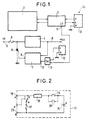
- the reference 1 designates the various electromechanical circuits of the franking machine, which will not be described in detail insofar as they are well known in the art and do not are not modified to implement the invention.
- Reference 2 designates the microcontroller for controlling circuits 1, which is associated to various memories (located in block 1), in particular a memory containing the postage counters made, the content of which must be protected against any alteration (including erasure) accidental or fraudulent.
- Circuits 1 and 2 are supplied by a stabilized and regulated V DC voltage, produced from a rectified and filtered V voltage applied at 3, via a regulator 4 producing the V DC voltage (generally + 5 V ) necessary for the operation of the various integrated circuits of the machine.
- a protection fuse 5 is provided at the input such that, if the voltage delivered at 6 by the regulator 4 exceeds a high limit detected by a supervisor circuit 7 (for example a circuit of the MC 3423 type), the latter controls an output 9 for controlling a thyristor 8 mounted between the downstream terminal of the fuse 5 and the earth, so that the conduction of the thyristor causes a short circuit and an immediate cut of the fuse 5.
- a supervisor circuit 7 for example a circuit of the MC 3423 type
- Certain supervisors such as the aforementioned MC 3423 , also have an auxiliary input 10 making it possible to control by application of a logic signal the blowing of the fuse.
- This input can advantageously be connected to an output 11, designated CF ("fuse control"), of the microcontroller 2 so that the latter can irreversibly interrupt the operation of the machine by causing the fuse to blow when it finds a fault.
- major for example of the type "inconsistent memory content”
- detects an attempt at fraud the fuse 5 is disposed inside the sealed enclosure, so that its replacement by the user is not authorized.
- a temperature detecting member capable of detecting in a "non-reversible” way the exposure of the machine at an excessively low and / or high temperature and issue an inhibition signal suitable for prohibiting any use of the device (by "not reversible”, we mean a change state which can only be reversed by an external action to the detector, for example the change of a component electric such as a fuse, pressing a reset button placed in the protected enclosure, or the application of an electrical signal external not controllable by the user; it is therefore an irreversibility logical, capable of being restored under conditions specific, not absolute physical irreversibility).
- the detector member 12 essentially presents in the form of a dipole comprising two terminals A and B of which one, A, for example provides a permanent "high" logic signal when the temperature threshold (low and / or high) has been crossed a times, even briefly.
- This logical signal which will be called “alert signal” can by example be applied to an additional auxiliary input of the supervisor circuit 7 or, as illustrated, at the single auxiliary input 10 via a comparator 13 receiving the signal from of the detection device 12 and the signal CF from the microcontroller 11, or alternatively, as illustrated in dashed lines in 14, in connecting input A directly to one of the inputs of the microcontroller 2, the state of this input being checked by the microcontroller each time the machine is powered up or periodically in a supervision loop.
- alert signal can by example be applied to an additional auxiliary input of the supervisor circuit 7 or, as illustrated, at the single auxiliary input 10 via a comparator 13 receiving the signal from of the detection device 12 and the signal CF from the microcontroller 11, or alternatively, as illustrated in dashed lines in 14, in connecting input A directly to one of the inputs of the microcontroller 2, the state of this input being checked by the microcontroller each time the machine is powered up or periodically in a supervision loop.
- the contact 16 is open, no current flows in the loop, and the battery therefore does not discharge.
- the temperature drops, and for a value between - 5 ° C and -15 ° C (taking into account the tolerance margin of the thermostatic contact, which is a common, inexpensive component), the thermostatic contact 16 closes, a current of an intensity of 5.I n flows in the loop and the fuse 17 blows in a few milliseconds; as soon as the fuse breaks, the battery stops flowing.
- This circuit 12 thus constitutes an irreversible temperature detector low. Seen between points A and B (terminals 19 and 20), it is therefore behaves like a closed contact when the machine has remained at a temperature above -10 ° C ( ⁇ 5 ° C); otherwise, the contact is open, the transition to this state taking place so irreversible and commanding the neutralization of the machine as indicated above.
- the latter can, instead of acting on the fuse main, simply prohibit the making of postage, this prohibition being advantageously accompanied by an alarm visual such as the lighting of a light-emitting diode or the display a "low temperature" message on an alphanumeric display of the machine.
- One of the drawbacks of the module in FIG. 2 is that, when the leaded part of the machine is, for example, transported by the after-sales service in the trunk of a car, the temperature may fall below the trigger level of the detector, causing the fuse to break.
- a switch K is added to member 12 in series with the fuse, with two positions “service” (S) and “transport” (T), the position of the switch K being known to the microcontroller by terminal A 'connected to the latter.
- S service
- T transport
- the fuse is isolated from the battery and cannot be blown.
- the microcontroller sees point A 'connected to ground and point A in the air. In this case, the machine displays a message "Detector out service "and it prohibits the making of postage.
- position "service” the microcontroller notes that the input A 'is in the air and that input A is grounded through the fuse; he then authorizes the realization of postage.
- the switch K can be replaced by three terminals can receive a removable jumper occupying position T or S.
- the absence of a jumper then corresponds to the test; indeed, the microcontroller finds that A and A 'are in the air and deduces that the rider is in position S and the fuse is cut. The machine then displays "Temperature fault".
- Yet another variant could be to mount the fuse on a support so as to make it removable, the machine being transported without the fuse which would be installed on its support at when the machine is put into service at the user's home.
- This flip-flop 21 comprises a power input 22 permanently connected to the battery 15 (therefore even if the machine is stopped or disconnected), a grounding input 23, a logic arming input ("Set") 24, a reset logic input 25 and a logic output 26.
- Inputs 24 and 25 are biased at the positive voltage of the battery by resistors 27 and 28, so that outlet 26 is initially at the low logic level.
- Thermostatic contact 16 is mounted between input 24 and earth so that when it closes it forces the passage to high level (battery voltage 15) of output 26 of the rocker, which will remain in this state until you press a reset button 29 mounted between input 25 and earth, this key being clearly heard placed inside the enclosure leaded.
- a resistor 30 Just apply the signal from output 26 to terminal A of the circuit 12, via a resistor 30, to have functionality identical to that of the embodiment of FIG. 2, but without require replacement of a component for recommissioning of the device.
- the member 12 then comprises, in place and place of resistance 28 and of reset button 29, an additional terminal 31 (input C) connected to an output of the microcontroller 2 (as illustrated in 14 in FIG. 1) and connected to reset input 25 of flip-flop 21 via a series resistor 32, a resistance-capacity circuit 33 and a door 34.
- thermostatic contact 16 it is possible to place in parallel on the thermostatic contact 16 a second thermostatic contact 35 (FIGS. 2, 3 and 4) which is will close when the temperature exceeds a high temperature threshold, for example 70 ° C. Crossing this upper threshold will produce, as in the previous case, the melting of fuse 17 or well the change of state of flip-flop 21.
- a high temperature threshold for example 70 ° C.
- Crossing this upper threshold will produce, as in the previous case, the melting of fuse 17 or well the change of state of flip-flop 21.
- This configuration allows in particular to omit the thermal protection fuse which was placed in series with the main fuse in known machines. It will be noted in this regard that, if a circuit of the type of that of Figures 3 and 4, we can achieve the same result with the possibility reset without changing components, providing thus an additional advantage compared to previous systems.
- thermostatic contacts present the disadvantage of not being able to determine whether the trigger comes from an excessively high or excessively high temperature low. If you want to be able to do it, you can use two separate circuits, one by thermostatic contact. Both fixtures, which can be powered by the same battery, apply to the microcontroller of the signals on separate inputs from it, rearming can be common.
- the voltage at point A corresponding to the high logic level of the rocker, is equal to the voltage of the battery 15.
- the microcontroller has an appropriate analog input: when it measures a voltage greater than 2.5 V on this input, it will know that the temperature threshold has not been crossed and that the battery is not fully used, provided that the complementary output of the RS flip-flop is connected to this input. Knowing the battery voltage also allows the microcontroller to manage alarms and messages, for example warning the user that the battery needs to be changed, when the voltage drops below 2.6 V.
- thermoswitch 16 of FIGS. 2 to 4 is then replaced by an electronic assembly using a temperature-sensitive component, such as a PTC or CTN thermistor, for example from the KTY8 series from Philips.
- a temperature-sensitive component such as a PTC or CTN thermistor, for example from the KTY8 series from Philips.
- a comparator 37 has one of its inputs E 1 connected to the midpoint of a voltage divider consisting of a fixed resistor 38 and a thermistor 39 ; the other input E 2 is connected to the midpoint of a divider bridge constituted by a fixed resistor 40 and an adjustable resistor 41.
- the voltage on the input E 1 will therefore decrease when the temperature increases if the thermistor 39 is a CTN , and vice versa for a CTP.
- the adjustable resistor 41 makes it possible, in a known manner, to adjust the switching threshold of the comparator 37. If the voltage variation on the input E 1 is insufficient to obtain a precise adjustment by the resistor 41, it suffices to insert a stage amplifier between this input E 1 and the midpoint of the divider bridge 38, 39. When the threshold set by the resistor 41 is crossed, a current flows in the resistor 42 connected to the output of the comparator 37, so that the comparator behaves , vis-à-vis this resistor 42, like a switch triggered at a temperature regulated by the resistor 41.
- this XY dipole therefore behaves at the like the equivalent diagram in Figure 6.
- equivalent contact 45 is open, the consumption of the dipole being in this case low and equal to the current crossing resistor 46, equivalent to the network of resistors 38, 39, 40 and 41, which represents a high value.
- equivalent contact 45 closes, which induces a strong increase in the current consumed by the dipole, resistance 42 being of a value much lower than that of resistance equivalent 46.
- a fuse 17 and a battery 15 are associated with this circuit 36, as long as the temperature threshold is not crossed, the contact of the dipole is open and the battery delivers a very low current, significantly lower than the current I n necessary to blow the fuse; as soon as the temperature threshold is reached, the consumption of the dipole greatly exceeds the current I n and the fuse blows.
- terminal A of the circuit in Figure 7 is connected to the analog input of the microcontroller, it checks the voltage supplied by the battery if the fuse is present, and detects a zero voltage in the event that the fuse is cut.
- the fuse 17 can be replaced by a bistable rocker.
- the output of the comparator controls directly the entrance to the scale.
- it is possible to monitor a low threshold and a high threshold by splitting the comparator 37 and the resistors 40 and 41 in the circuit 36, the divider bridge 38, 39 may, however, remain common to the two comparators.
- thermocouple the condition of providing an amplifier stage between the comparator input and the thermocouple.
- the same scheme can be applied to monitoring a threshold high temperature.
- a monitoring body fine of the specified range of allowable temperatures of the machine an organ that only turns on when the temperature is near the limits of this beach.
- teachings of the invention can be applied to such surveillance, in this case taking place only during periods of machine operation and no longer, as before, permanently (i.e. the machine is at stopped or running, energized or not).
- a machine specified to operate at a temperature room between 0 and 40 ° C can heat up normally ten degrees when operating at its maximum speed or power characteristics.
- the internal temperature of the machine does not exceed 50 ° C and, if exceeded, to trigger an alarm telling the user to notify the after-sales service, cause a temporary shutdown of the machine to allow cooling, or even reducing the rate of use until the temperature returns to normal.
- the machine is in operation, therefore powered up, and the microcontroller has analog inputs, if we connect to one of these inputs the midpoint of a divider bridge consisting of a resistor and a thermistor (for example the voltage taken at point Z of the circuit of figure 36 of the figure 5), there is then a thermometer of sufficient accuracy to perform the desired function. Cyclically, for example all the minutes, the microcontroller converts the voltage from the thermometer and compares the result to a pre-recorded threshold; if the threshold is exceeded, it will trigger the alarm, temporary stop or rate decrease as previously mentioned.
- the method of measurement just described has the drawback not to measure the actual temperature rise of the machine but simply to check that there is no temperature overshoot maximum. So if the ambient temperature is 25 ° C and that the normal temperature rise is ten degrees, the monitoring threshold should be placed at 35 ° C instead of 50 ° C in the previous example; on the other hand, in the case of an abnormal heating of twenty degrees, the internal temperature would rise to 45 ° C, a lower temperature at 50 ° C of the pre-recorded threshold.
- the machine can be equipped a second thermometer responsible for measuring the ambient temperature of the machine.
- this room thermometer is fixed on one of the metal parts of the machine located in contact with ambient air or, at the very least, fixed on a cold part of the machine, i.e. in an area where overheating compared to the atmosphere is minimal.
- the room thermometer is mounted identically to the first thermometer, and it is connected to another analog input of the microcontroller.
- the latter periodically removes the two temperatures, calculates the differential value corresponding to the temperature rise by subtracting the two temperatures and then comparing the pre-recorded authorized warm-up result. Like before, if exceeded, alarms and backup measures are triggered, thus protecting the machine before the occurrence of a breakdown.
Landscapes
- Physics & Mathematics (AREA)
- General Physics & Mathematics (AREA)
- Engineering & Computer Science (AREA)
- Automation & Control Theory (AREA)
- Computer Hardware Design (AREA)
- General Engineering & Computer Science (AREA)
- Protection Of Static Devices (AREA)
- Burglar Alarm Systems (AREA)
- Emergency Alarm Devices (AREA)
- Storage Device Security (AREA)
Description
- une pile 15, par exemple une pile au lithium susceptible de débiter un courant de 10 mA à des températures pouvant aller jusqu'à -20 °C ;
- un contact thermostatique classique 16 à disque ou à lame bimétallique, présentant un contact ouvert lorsque la température est supérieure à + 3 °C; si la température descend, le contact se ferme lorsque la température atteint -10 °C (± 5°C) et s'ouvre à nouveau lorsque celle-ci remonte à 0 °C (± 3°C) ;
- un fusible calibré 17, caractérisé par son courant de fusion In, par exemple In = 2 mA, de tels fusibles calibrés étant par exemple disponibles auprès de la société Littlefuse, et
- une résistance 18 de limitation du courant, par exemple calculée pour limiter le courant à 5.In, soit 10 mA dans l'exemple choisi.
Claims (15)
- Un dispositif pour détecter le franchissement d'un seuil prédéterminé de température par les circuits d'un appareil électronique sécurisé, notamment ceux d'une machine à affranchir, et interdire l'utilisation ultérieure de cet appareil après un tel franchissement, ce dispositif comportant, disposés à l'intérieur d'une enceinte protégée :caractérisé en ce que l'organe détecteur de température est un organe électrique comportant :un organe détecteur de température (12), propre à passer de manière non réversible, lors d'un franchissement dudit seuil prédéterminé, d'un premier état stable à un second état stable et délivrant un signal d'alerte lorsqu'il se trouve dans ce second état, etdes moyens de commande, coopérant avec le détecteur pour délivrer, en réponse au signal d'alerte, un signal d'inhibition propre à interdire toute utilisation de l'appareil électronique,une source de tension (15), délivrant une tension continue,un composant électrique ou électronique (17 ; 21) susceptible de prendre deux états correspondant auxdits premier et second états stables, etun interrupteur thermostatique (16 ; 36) fermant, pour des valeurs de températures situées au-delà dudit seuil prédéterminé, un circuit comprenant la source de tension et le composant électrique ou électronique de manière que le passage d'un courant dans l'interrupteur thermostatique provoque une transition du premier au second état du composant électrique ou électronique.
- Le dispositif de la revendication 1, caractérisé en ce que l'organe détecteur de température est un détecteur de températures basses, l'interrupteur thermostatique fermant le circuit pour des valeurs de températures inférieures audit seuil.
- Le dispositif de la revendication 1, caractérisé en ce que le composant électrique ou électronique est un fusible (17) monté dans une maille de courant comprenant également la source de tension et l'interrupteur thermostatique.
- Le dispositif de la revendication 3, caractérisé en ce que le signal d'alerte est donné par la tension prélevée au point commun (A) du fusible (17) et de l'interrupteur thermostatique (16 ; 35).
- Le dispositif de la revendication 1, caractérisé en ce que le composant électrique ou électronique est un bistable RS (21) dont l'entrée de déclenchement (24) est reliée à l'interrupteur thermostatique (16 ; 35).
- Le dispositif de la revendication 1, caractérisé en ce que le signal d'inhibition délivré par les moyens de commande est appliqué à une entrée d'un microcontrôleur (2) de pilotage de l'appareil électronique et en ce que ce microcontrôleur se place, en présence du signal d'inhibition, dans un mode interdisant toute utilisation de l'appareil électronique.
- Le dispositif de la revendication 6, caractérisé en ce que le signal d'inhibition, lorsqu'il est délivré, possède un niveau variable représentatif de la tension délivrée par la source de tension de l'organe détecteur de température, en ce que ce signal est appliqué sur une entrée analogique du microcontrôleur (2) et en ce que ce dernier, en cas de tension inférieure à une valeur limite donnée, délivre un message d'avertissement de changement de pile et/ou se place dans un mode interdisant toute utilisation de l'appareil électronique.
- Le dispositif de la revendication 1, caractérisé en ce que le signal d'inhibition délivré par les moyens de commande est appliqué à une entrée d'un circuit superviseur (7) du circuit d'alimentation (4, 5, 6, 8) de l'appareil électronique et en ce que ce circuit superviseur, en présence du signal d'inhibition, met hors service l'alimentation de l'appareil électronique.
- Le dispositif de la revendication 1, pour détecter le franchissement par l'appareil aussi bien d'un seuil inférieur de température que d'un seuil supérieur de température afin de signaler toute excursion de température hors des limites d'une plage de températures admissibles, caractérisé en ce qu'il est prévu un organe détecteur de température commun délivrant un signal d'alerte commun, cet organe détecteur de température comportant deux interrupteurs thermostatiques (16, 35) montés en parallèle, l'un fermant le circuit pour des valeurs de températures inférieures audit seuil inférieur et l'autre fermant le circuit pour des valeurs de températures supérieures audit seuil supérieur.
- Le dispositif de la revendication 1, pour détecter le franchissement par l'appareil aussi bien d'un seuil inférieur de température que d'un seuil supérieur de température afin de signaler toute excursion de température hors des limites d'une plage de températures admissibles, caractérisé en ce qu'il est prévu deux organes détecteurs de température distincts, réglés sur chacun des seuils respectifs et délivrant deux signaux d'alerte distincts correspondants.
- Le dispositif de la revendication 1, caractérisé en ce que l'interrupteur thermostatique est un thermocontact bimétallique (16).
- Le dispositif de la revendication 1, caractérisé en ce que l'interrupteur thermostatique est un circuit électronique (35) commandé par thermistance (39) ou thermocouple.
- Le dispositif de la revendication 12, caractérisé en ce qu'il est prévu un interrupteur thermostatique auxiliaire (47) non électronique se fermant à une température voisine dudit seuil prédéterminé mais située en-deçà de celui-ci, monté en série avec ledit circuit électronique (35) commandé par thermistance ou thermocouple pour n'alimenter celui-ci que lorsque la température approche ledit seuil prédéterminé.
- Le dispositif de la revendication 12, notamment pour la prévention d'échauffements excessifs de l'appareil électronique en cours d'utilisation de celui-ci, caractérisé en ce que ledit circuit électronique commandé par thermistance ou thermocouple délivre également un signal représentatif de la température opérationnelle de l'appareil électronique, en ce que ce signal est appliqué à une entrée analogique d'un microcontrôleur (2) de pilotage de l'appareil électronique et en ce que ce dernier, en cas de température opérationnelle supérieure à une température de référence, délivre un message d'avertissement et/ou se place dans un mode interdisant temporairement toute utilisation de l'appareil électronique.
- Le dispositif de la revendication 14, dans lequel ladite température de référence est un paramètre variable, fonction de la température de l'environnement de l'appareil électronique, de manière à ne commander le microcontrôleur (2) que lorsque l'écart différentiel entre température de l'environnement et température opérationnelle dépasse une valeur limite prédéterminée.
Applications Claiming Priority (2)
| Application Number | Priority Date | Filing Date | Title |
|---|---|---|---|
| FR9314381A FR2713372B1 (fr) | 1993-12-01 | 1993-12-01 | Dispositif de protection thermique pour appareil électronique sécurisé, notamment machine à affranchir. |
| FR9314381 | 1993-12-01 |
Publications (2)
| Publication Number | Publication Date |
|---|---|
| EP0656610A1 EP0656610A1 (fr) | 1995-06-07 |
| EP0656610B1 true EP0656610B1 (fr) | 1998-03-18 |
Family
ID=9453418
Family Applications (1)
| Application Number | Title | Priority Date | Filing Date |
|---|---|---|---|
| EP94402744A Expired - Lifetime EP0656610B1 (fr) | 1993-12-01 | 1994-11-30 | Dispositif de protection thermique pour appareil électronique sécurisé, notamment machine à affranchir |
Country Status (4)
| Country | Link |
|---|---|
| US (1) | US5659454A (fr) |
| EP (1) | EP0656610B1 (fr) |
| DE (1) | DE69409070T2 (fr) |
| FR (1) | FR2713372B1 (fr) |
Families Citing this family (82)
| Publication number | Priority date | Publication date | Assignee | Title |
|---|---|---|---|---|
| US7707920B2 (en) | 2003-12-31 | 2010-05-04 | Sd3, Llc | Table saws with safety systems |
| US9724840B2 (en) * | 1999-10-01 | 2017-08-08 | Sd3, Llc | Safety systems for power equipment |
| US7536238B2 (en) | 2003-12-31 | 2009-05-19 | Sd3, Llc | Detection systems for power equipment |
| US7481140B2 (en) | 2005-04-15 | 2009-01-27 | Sd3, Llc | Detection systems for power equipment |
| US7100483B2 (en) * | 2000-08-14 | 2006-09-05 | Sd3, Llc | Firing subsystem for use in a fast-acting safety system |
| US7055417B1 (en) | 1999-10-01 | 2006-06-06 | Sd3, Llc | Safety system for power equipment |
| US7836804B2 (en) | 2003-08-20 | 2010-11-23 | Sd3, Llc | Woodworking machines with overmolded arbors |
| US8459157B2 (en) | 2003-12-31 | 2013-06-11 | Sd3, Llc | Brake cartridges and mounting systems for brake cartridges |
| US20020017179A1 (en) | 2000-08-14 | 2002-02-14 | Gass Stephen F. | Miter saw with improved safety system |
| US7024975B2 (en) | 2000-08-14 | 2006-04-11 | Sd3, Llc | Brake mechanism for power equipment |
| US20050041359A1 (en) | 2003-08-20 | 2005-02-24 | Gass Stephen F. | Motion detecting system for use in a safety system for power equipment |
| US7377199B2 (en) | 2000-09-29 | 2008-05-27 | Sd3, Llc | Contact detection system for power equipment |
| US7137326B2 (en) | 2000-08-14 | 2006-11-21 | Sd3, Llc | Translation stop for use in power equipment |
| US7098800B2 (en) | 2003-03-05 | 2006-08-29 | Sd3, Llc | Retraction system and motor position for use with safety systems for power equipment |
| US7610836B2 (en) | 2000-08-14 | 2009-11-03 | Sd3, Llc | Replaceable brake mechanism for power equipment |
| US7290472B2 (en) | 2002-01-14 | 2007-11-06 | Sd3, Llc | Miter saw with improved safety system |
| US7600455B2 (en) | 2000-08-14 | 2009-10-13 | Sd3, Llc | Logic control for fast-acting safety system |
| US6857345B2 (en) | 2000-08-14 | 2005-02-22 | Sd3, Llc | Brake positioning system |
| US7827890B2 (en) | 2004-01-29 | 2010-11-09 | Sd3, Llc | Table saws with safety systems and systems to mount and index attachments |
| US7509899B2 (en) | 2000-08-14 | 2009-03-31 | Sd3, Llc | Retraction system for use in power equipment |
| US8065943B2 (en) | 2000-09-18 | 2011-11-29 | Sd3, Llc | Translation stop for use in power equipment |
| US7350444B2 (en) * | 2000-08-14 | 2008-04-01 | Sd3, Llc | Table saw with improved safety system |
| US7284467B2 (en) | 2000-08-14 | 2007-10-23 | Sd3, Llc | Apparatus and method for detecting dangerous conditions in power equipment |
| US7210383B2 (en) | 2000-08-14 | 2007-05-01 | Sd3, Llc | Detection system for power equipment |
| US7171879B2 (en) | 2001-07-02 | 2007-02-06 | Sd3, Llc | Discrete proximity detection system |
| US20030056853A1 (en) | 2001-09-21 | 2003-03-27 | Gass Stephen F. | Router with improved safety system |
| US7197969B2 (en) | 2001-09-24 | 2007-04-03 | Sd3, Llc | Logic control with test mode for fast-acting safety system |
| US7225712B2 (en) | 2000-08-14 | 2007-06-05 | Sd3, Llc | Motion detecting system for use in a safety system for power equipment |
| US7712403B2 (en) | 2001-07-03 | 2010-05-11 | Sd3, Llc | Actuators for use in fast-acting safety systems |
| US6994004B2 (en) | 2000-09-29 | 2006-02-07 | Sd3, Llc | Table saw with improved safety system |
| US7350445B2 (en) | 2003-08-20 | 2008-04-01 | Sd3, Llc | Brake cartridge for power equipment |
| US8061245B2 (en) | 2000-09-29 | 2011-11-22 | Sd3, Llc | Safety methods for use in power equipment |
| US9927796B2 (en) | 2001-05-17 | 2018-03-27 | Sawstop Holding Llc | Band saw with improved safety system |
| US7077039B2 (en) | 2001-11-13 | 2006-07-18 | Sd3, Llc | Detection system for power equipment |
| US7231856B2 (en) | 2001-06-13 | 2007-06-19 | Sd3, Llc | Apparatus and method for detecting dangerous conditions in power equipment |
| US7472634B2 (en) | 2003-08-20 | 2009-01-06 | Sd3, Llc | Woodworking machines with overmolded arbors |
| US7000514B2 (en) | 2001-07-27 | 2006-02-21 | Sd3, Llc | Safety systems for band saws |
| US7353737B2 (en) | 2001-08-13 | 2008-04-08 | Sd3, Llc | Miter saw with improved safety system |
| US7308843B2 (en) | 2000-08-14 | 2007-12-18 | Sd3, Llc | Spring-biased brake mechanism for power equipment |
| US8771183B2 (en) | 2004-02-17 | 2014-07-08 | Abbott Diabetes Care Inc. | Method and system for providing data communication in continuous glucose monitoring and management system |
| AU2003303597A1 (en) | 2002-12-31 | 2004-07-29 | Therasense, Inc. | Continuous glucose monitoring system and methods of use |
| US7587287B2 (en) | 2003-04-04 | 2009-09-08 | Abbott Diabetes Care Inc. | Method and system for transferring analyte test data |
| US8066639B2 (en) | 2003-06-10 | 2011-11-29 | Abbott Diabetes Care Inc. | Glucose measuring device for use in personal area network |
| US9788771B2 (en) | 2006-10-23 | 2017-10-17 | Abbott Diabetes Care Inc. | Variable speed sensor insertion devices and methods of use |
| US7766829B2 (en) | 2005-11-04 | 2010-08-03 | Abbott Diabetes Care Inc. | Method and system for providing basal profile modification in analyte monitoring and management systems |
| US8226891B2 (en) | 2006-03-31 | 2012-07-24 | Abbott Diabetes Care Inc. | Analyte monitoring devices and methods therefor |
| US7620438B2 (en) | 2006-03-31 | 2009-11-17 | Abbott Diabetes Care Inc. | Method and system for powering an electronic device |
| US20080199894A1 (en) | 2007-02-15 | 2008-08-21 | Abbott Diabetes Care, Inc. | Device and method for automatic data acquisition and/or detection |
| US8123686B2 (en) | 2007-03-01 | 2012-02-28 | Abbott Diabetes Care Inc. | Method and apparatus for providing rolling data in communication systems |
| US7928850B2 (en) | 2007-05-08 | 2011-04-19 | Abbott Diabetes Care Inc. | Analyte monitoring system and methods |
| US8461985B2 (en) | 2007-05-08 | 2013-06-11 | Abbott Diabetes Care Inc. | Analyte monitoring system and methods |
| US8665091B2 (en) | 2007-05-08 | 2014-03-04 | Abbott Diabetes Care Inc. | Method and device for determining elapsed sensor life |
| US8456301B2 (en) | 2007-05-08 | 2013-06-04 | Abbott Diabetes Care Inc. | Analyte monitoring system and methods |
| CN103251414B (zh) | 2007-06-21 | 2017-05-24 | 雅培糖尿病护理公司 | 用于分析物水平的检测的设备 |
| EP2171031B1 (fr) | 2007-06-21 | 2018-12-05 | Abbott Diabetes Care Inc. | Dispositifs et procédés de gestion de la santé |
| US7523008B1 (en) * | 2008-03-10 | 2009-04-21 | International Business Machines Corporation | Thermal calibration in cell processor |
| US7826382B2 (en) | 2008-05-30 | 2010-11-02 | Abbott Diabetes Care Inc. | Close proximity communication device and methods |
| DE102008043760B3 (de) * | 2008-11-14 | 2010-06-17 | BSH Bosch und Siemens Hausgeräte GmbH | Verfahren zum Ermitteln von Betriebsbedingungen eines Hausgeräts |
| US9402544B2 (en) | 2009-02-03 | 2016-08-02 | Abbott Diabetes Care Inc. | Analyte sensor and apparatus for insertion of the sensor |
| WO2010127050A1 (fr) | 2009-04-28 | 2010-11-04 | Abbott Diabetes Care Inc. | Détection d'erreur dans des données de répétition critiques dans un système de capteur sans fil |
| WO2010127187A1 (fr) | 2009-04-29 | 2010-11-04 | Abbott Diabetes Care Inc. | Procédé et système assurant une communication de données dans la surveillance du glucose en continu et système de gestion |
| WO2010138856A1 (fr) | 2009-05-29 | 2010-12-02 | Abbott Diabetes Care Inc. | Systèmes d'antenne de dispositif médical comportant des configurations d'antenne externe |
| EP2473099A4 (fr) | 2009-08-31 | 2015-01-14 | Abbott Diabetes Care Inc | Système de surveillance de substance à analyser et procédés de gestion de l'énergie et du bruit |
| WO2011026147A1 (fr) | 2009-08-31 | 2011-03-03 | Abbott Diabetes Care Inc. | Dispositif et procédés de traitement de signal d'analyte |
| JP5795584B2 (ja) | 2009-08-31 | 2015-10-14 | アボット ダイアベティス ケア インコーポレイテッドAbbott Diabetes Care Inc. | 医療用装置 |
| ES2881798T3 (es) | 2010-03-24 | 2021-11-30 | Abbott Diabetes Care Inc | Insertadores de dispositivos médicos y procedimientos de inserción y uso de dispositivos médicos |
| CN103619255B (zh) | 2011-02-28 | 2016-11-02 | 雅培糖尿病护理公司 | 与分析物监测装置关联的装置、系统和方法以及结合了它们的装置 |
| US9069536B2 (en) | 2011-10-31 | 2015-06-30 | Abbott Diabetes Care Inc. | Electronic devices having integrated reset systems and methods thereof |
| CA2840640C (fr) | 2011-11-07 | 2020-03-24 | Abbott Diabetes Care Inc. | Dispositif et procedes de controle de substance a analyser |
| AU2012352560B2 (en) | 2011-12-11 | 2017-01-19 | Abbott Diabetes Care Inc. | Analyte sensor devices, connections, and methods |
| US9299451B2 (en) * | 2012-01-20 | 2016-03-29 | International Business Machines Corporation | Tamper resistant electronic system utilizing acceptable tamper threshold count |
| US9968306B2 (en) | 2012-09-17 | 2018-05-15 | Abbott Diabetes Care Inc. | Methods and apparatuses for providing adverse condition notification with enhanced wireless communication range in analyte monitoring systems |
| CN104065041A (zh) * | 2013-03-18 | 2014-09-24 | 鸿富锦精密电子(天津)有限公司 | 电源保护电路 |
| CA2984939A1 (fr) | 2015-05-14 | 2016-11-17 | Abbott Diabetes Care Inc. | Instruments d'introduction de dispositifs medicaux compacts et systemes et procedes associes |
| KR101922553B1 (ko) * | 2015-11-17 | 2018-11-27 | 주식회사 엘지화학 | 바이메탈을 이용한 릴레이 독립 제어 시스템 및 방법 |
| KR20170116472A (ko) * | 2016-04-11 | 2017-10-19 | 주식회사 엘지화학 | 검전기 및 시그널 퓨즈를 이용한 모스펫 릴레이 보호 장치 및 보호 방법 |
| US11071478B2 (en) | 2017-01-23 | 2021-07-27 | Abbott Diabetes Care Inc. | Systems, devices and methods for analyte sensor insertion |
| CN110208622B (zh) * | 2018-07-27 | 2020-02-11 | 南京瑞贻电子科技有限公司 | 一种具有断电保护功能的便携式录波仪 |
| MX2021007294A (es) | 2018-12-21 | 2021-07-15 | Abbott Diabetes Care Inc | Sistemas, dispositivos y metodos para la insercion de sensores de analito. |
| EP4203819B1 (fr) | 2020-08-31 | 2024-07-31 | Abbott Diabetes Care Inc. | Systèmes, dispositifs et procédés d'insertion de capteur d'analyte |
| ES3000715T3 (en) | 2020-09-15 | 2025-03-03 | Abbott Diabetes Care Inc | Device for analyte monitoring |
| JP2024527596A (ja) | 2021-07-16 | 2024-07-25 | アボット ダイアベティス ケア インコーポレイテッド | 検体監視のためのシステム、装置、及び方法 |
Family Cites Families (3)
| Publication number | Priority date | Publication date | Assignee | Title |
|---|---|---|---|---|
| US4035756A (en) * | 1976-01-26 | 1977-07-12 | Therm-O-Disc Incorporated | Two temperature thermostat |
| GB8413912D0 (en) * | 1984-05-31 | 1984-07-04 | Elmwood Sensors | Electrical switches |
| FR2675965B1 (fr) * | 1991-04-26 | 1993-08-06 | Secap | Dispositif de protection thermique dans un domaine limite de temperatures, notamment pour appareil a enregistrement de donnees entretenues par piles et en particulier machine a affranchir. |
-
1993
- 1993-12-01 FR FR9314381A patent/FR2713372B1/fr not_active Expired - Fee Related
-
1994
- 1994-11-30 DE DE69409070T patent/DE69409070T2/de not_active Expired - Fee Related
- 1994-11-30 US US08/352,083 patent/US5659454A/en not_active Expired - Fee Related
- 1994-11-30 EP EP94402744A patent/EP0656610B1/fr not_active Expired - Lifetime
Also Published As
| Publication number | Publication date |
|---|---|
| US5659454A (en) | 1997-08-19 |
| DE69409070D1 (de) | 1998-04-23 |
| DE69409070T2 (de) | 1998-07-23 |
| FR2713372B1 (fr) | 1996-03-01 |
| EP0656610A1 (fr) | 1995-06-07 |
| FR2713372A1 (fr) | 1995-06-09 |
Similar Documents
| Publication | Publication Date | Title |
|---|---|---|
| EP0656610B1 (fr) | Dispositif de protection thermique pour appareil électronique sécurisé, notamment machine à affranchir | |
| EP2392062B1 (fr) | Dispositif de surveillance et de protection de l'alimentation d'un appareil électrique et procédé de mise en oeuvre de ce dispositif | |
| EP1764891B1 (fr) | Déclencheur électronique pourvu de moyens de surveillance et procédé de surveillance correspondant | |
| FR2796723A1 (fr) | Dispositif electronique intelligent et procede de prediction de pannes dans un tel dispositif | |
| FR2673288A1 (fr) | Detecteur d'anomalie de temperature pour appareil electronique. | |
| EP2682972B1 (fr) | Dispositif de détection d'état ouvert ou fermé d'interrupteur et dispositif de monitorage de relais de protection de transformateur associé | |
| EP1870976B1 (fr) | Dispositif de protection contre les surtensons à capacité améliorée de mise en sécurité par déconnexion et procédé correspondant | |
| FR2974684A1 (fr) | Systeme de protection et de supervision d'un circuit de distribution d'energie electrique a courant continu | |
| EP0715172B1 (fr) | Appareil de contrôle pour socle de prise de courant à contact de terre | |
| EP2035618B1 (fr) | Appareil de repassage comportant un dispositif de securite et procede de securisation d'un appareil de repassage | |
| WO1992020085A1 (fr) | Dispositif de protection thermique dans un domaine limite de temperatures | |
| FR3112658A1 (fr) | Système de verrouillage pour armoire électrique et procédé associé | |
| EP0536058B2 (fr) | Déclencheur électronique comportant des moyens de signalisation locale du type de défaut détecté | |
| FR2841686A1 (fr) | Installation de detection d'un evenement de surtemperature excessive d'un composant electronique et procede de detection de cet evenement | |
| EP0725372B1 (fr) | Dispositif de protection thermique pour machine à affranchir | |
| EP0253709A1 (fr) | Installation de surveillance comportant des détecteurs alimentés par une boucle | |
| FR2604568A1 (fr) | Procede et dispositif de commande d'un moteur electrique, notamment pour leve-vitre d'automobile | |
| EP1544049A1 (fr) | Système de contrôle de l'alimentation en énergie d'organes fonctionnels d'un réseau de bord de véhicules | |
| EP0098760A2 (fr) | Procédé de mise en surveillance d'un site à protéger et installation de surveillance mettant en oeuvre ce procédé | |
| FR2727533A1 (fr) | Dispositif de detection et de securite pour appareil de cuisson | |
| EP0069182A1 (fr) | Dispositif de sécurité pour appareils électriques et notamment pour postes récepteurs de télévision | |
| FR3059783A1 (fr) | Procede de fabrication d'un capteur de mesure pour un disjoncteur | |
| FR2911428A1 (fr) | Procede de protection d'un circuit electrique et dispositif de protection associe | |
| FR2723237A1 (fr) | Dispositif de detection d'incendie avec transmission de signal electrique analogique a une unite centrale | |
| EP4075471A1 (fr) | Module auxiliaire de protection électrique, appareil de protection électrique comportant un tel module, et procédé de fonctionnement associé |
Legal Events
| Date | Code | Title | Description |
|---|---|---|---|
| PUAI | Public reference made under article 153(3) epc to a published international application that has entered the european phase |
Free format text: ORIGINAL CODE: 0009012 |
|
| AK | Designated contracting states |
Kind code of ref document: A1 Designated state(s): DE FR GB |
|
| 17P | Request for examination filed |
Effective date: 19951011 |
|
| GRAG | Despatch of communication of intention to grant |
Free format text: ORIGINAL CODE: EPIDOS AGRA |
|
| 17Q | First examination report despatched |
Effective date: 19970610 |
|
| GRAG | Despatch of communication of intention to grant |
Free format text: ORIGINAL CODE: EPIDOS AGRA |
|
| GRAH | Despatch of communication of intention to grant a patent |
Free format text: ORIGINAL CODE: EPIDOS IGRA |
|
| GRAH | Despatch of communication of intention to grant a patent |
Free format text: ORIGINAL CODE: EPIDOS IGRA |
|
| GRAA | (expected) grant |
Free format text: ORIGINAL CODE: 0009210 |
|
| AK | Designated contracting states |
Kind code of ref document: B1 Designated state(s): DE FR GB |
|
| GBT | Gb: translation of ep patent filed (gb section 77(6)(a)/1977) |
Effective date: 19980325 |
|
| REF | Corresponds to: |
Ref document number: 69409070 Country of ref document: DE Date of ref document: 19980423 |
|
| PLBE | No opposition filed within time limit |
Free format text: ORIGINAL CODE: 0009261 |
|
| STAA | Information on the status of an ep patent application or granted ep patent |
Free format text: STATUS: NO OPPOSITION FILED WITHIN TIME LIMIT |
|
| 26N | No opposition filed | ||
| REG | Reference to a national code |
Ref country code: GB Ref legal event code: IF02 |
|
| PGFP | Annual fee paid to national office [announced via postgrant information from national office to epo] |
Ref country code: GB Payment date: 20051026 Year of fee payment: 12 |
|
| PGFP | Annual fee paid to national office [announced via postgrant information from national office to epo] |
Ref country code: DE Payment date: 20051116 Year of fee payment: 12 |
|
| PGFP | Annual fee paid to national office [announced via postgrant information from national office to epo] |
Ref country code: FR Payment date: 20051118 Year of fee payment: 12 |
|
| PG25 | Lapsed in a contracting state [announced via postgrant information from national office to epo] |
Ref country code: DE Free format text: LAPSE BECAUSE OF NON-PAYMENT OF DUE FEES Effective date: 20070601 |
|
| GBPC | Gb: european patent ceased through non-payment of renewal fee |
Effective date: 20061130 |
|
| REG | Reference to a national code |
Ref country code: FR Ref legal event code: ST Effective date: 20070731 |
|
| PG25 | Lapsed in a contracting state [announced via postgrant information from national office to epo] |
Ref country code: GB Free format text: LAPSE BECAUSE OF NON-PAYMENT OF DUE FEES Effective date: 20061130 |
|
| PG25 | Lapsed in a contracting state [announced via postgrant information from national office to epo] |
Ref country code: FR Free format text: LAPSE BECAUSE OF NON-PAYMENT OF DUE FEES Effective date: 20061130 |