EP0656699A1 - Einrichtung zur leitungsungebundenen optischen Signalübertragung - Google Patents
Einrichtung zur leitungsungebundenen optischen Signalübertragung Download PDFInfo
- Publication number
- EP0656699A1 EP0656699A1 EP94118884A EP94118884A EP0656699A1 EP 0656699 A1 EP0656699 A1 EP 0656699A1 EP 94118884 A EP94118884 A EP 94118884A EP 94118884 A EP94118884 A EP 94118884A EP 0656699 A1 EP0656699 A1 EP 0656699A1
- Authority
- EP
- European Patent Office
- Prior art keywords
- light
- signal
- detection
- coherent
- receiving
- Prior art date
- Legal status (The legal status is an assumption and is not a legal conclusion. Google has not performed a legal analysis and makes no representation as to the accuracy of the status listed.)
- Granted
Links
- 230000005540 biological transmission Effects 0.000 title claims abstract description 319
- 230000003287 optical effect Effects 0.000 title description 64
- 238000001514 detection method Methods 0.000 claims abstract description 240
- 230000001427 coherent effect Effects 0.000 claims abstract description 218
- 230000010355 oscillation Effects 0.000 claims description 36
- 230000004044 response Effects 0.000 claims description 31
- 238000000034 method Methods 0.000 claims description 25
- 230000008054 signal transmission Effects 0.000 claims description 22
- 239000004065 semiconductor Substances 0.000 description 42
- 238000004891 communication Methods 0.000 description 38
- 238000010586 diagram Methods 0.000 description 33
- 230000001276 controlling effect Effects 0.000 description 21
- 238000013500 data storage Methods 0.000 description 12
- 238000009792 diffusion process Methods 0.000 description 12
- 238000012544 monitoring process Methods 0.000 description 9
- 238000006243 chemical reaction Methods 0.000 description 7
- 238000012545 processing Methods 0.000 description 6
- 230000008859 change Effects 0.000 description 4
- 230000000694 effects Effects 0.000 description 4
- 230000035559 beat frequency Effects 0.000 description 3
- 230000008901 benefit Effects 0.000 description 3
- 230000008569 process Effects 0.000 description 3
- 238000002347 injection Methods 0.000 description 2
- 239000007924 injection Substances 0.000 description 2
- 229910001218 Gallium arsenide Inorganic materials 0.000 description 1
- 241001481828 Glyptocephalus cynoglossus Species 0.000 description 1
- 241001597008 Nomeidae Species 0.000 description 1
- 235000001537 Ribes X gardonianum Nutrition 0.000 description 1
- 235000001535 Ribes X utile Nutrition 0.000 description 1
- 235000016919 Ribes petraeum Nutrition 0.000 description 1
- 244000281247 Ribes rubrum Species 0.000 description 1
- 235000002355 Ribes spicatum Nutrition 0.000 description 1
- 239000000853 adhesive Substances 0.000 description 1
- 230000001070 adhesive effect Effects 0.000 description 1
- 230000003321 amplification Effects 0.000 description 1
- 238000004364 calculation method Methods 0.000 description 1
- 239000011248 coating agent Substances 0.000 description 1
- 238000000576 coating method Methods 0.000 description 1
- 238000012790 confirmation Methods 0.000 description 1
- 230000007423 decrease Effects 0.000 description 1
- 238000011439 discrete element method Methods 0.000 description 1
- 239000011521 glass Substances 0.000 description 1
- 238000005286 illumination Methods 0.000 description 1
- 230000003993 interaction Effects 0.000 description 1
- 230000002045 lasting effect Effects 0.000 description 1
- 239000004973 liquid crystal related substance Substances 0.000 description 1
- 238000010295 mobile communication Methods 0.000 description 1
- 238000012986 modification Methods 0.000 description 1
- 230000004048 modification Effects 0.000 description 1
- 238000003199 nucleic acid amplification method Methods 0.000 description 1
- 230000000644 propagated effect Effects 0.000 description 1
- 230000001105 regulatory effect Effects 0.000 description 1
- 239000011347 resin Substances 0.000 description 1
- 229920005989 resin Polymers 0.000 description 1
- 239000007787 solid Substances 0.000 description 1
- 239000000758 substrate Substances 0.000 description 1
- 239000010409 thin film Substances 0.000 description 1
- 238000002834 transmittance Methods 0.000 description 1
Images


Classifications
-
- H—ELECTRICITY
- H04—ELECTRIC COMMUNICATION TECHNIQUE
- H04B—TRANSMISSION
- H04B10/00—Transmission systems employing electromagnetic waves other than radio-waves, e.g. infrared, visible or ultraviolet light, or employing corpuscular radiation, e.g. quantum communication
- H04B10/11—Arrangements specific to free-space transmission, i.e. transmission through air or vacuum
- H04B10/112—Line-of-sight transmission over an extended range
- H04B10/1123—Bidirectional transmission
- H04B10/1125—Bidirectional transmission using a single common optical path
Definitions
- the spatial data transmission using light which is free from indoor interference unlike a transmission using an electric wave as a medium, has been conventionally used for an information transmission for a short distance.
- This transmission system has employed an intensity modified detection (IMDD) method in which a light emission diode (LED) is used as a transmission light source and the modulation of the light intensity thereof allows data to be decoded.
- IMDD intensity modified detection
- LED light emission diode
- a spatial light transmission apparatus using a coherent detection technique has been put into practical use.
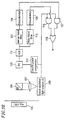
- the travelling direction of the locally oscillated diffused beam 8 is changed by an optical multiplexer/demultiplexer 3 . Thereafter, the diffused beam 8 is mixed with the signal beam 1 and is incident onto the light receiving element array 4 .
- a selfog lens array (intervals between lenses: 1 mm, and numerical aperture: 0.2) is used as the diffusion optical element 7 .
- the diffusion optical element 7 By means of this diffusion optical element 7 , the plane wave components of a diffused locally oscillated beam 8a at intervals of 0.05 degree exist over the light receiving array 4 .
- the angular range where the components exist is determined by the numerical aperture of the diffusion optical element 7 , which is a selfog lens array, and is ⁇ 11.5 degrees.
- the optical multiplexer/demultiplexer 3 is disposed on a rotation stage 10 to which a magnet 9 is attached.
- the central portion of the rotation stage 10 is adhered to a rod with a soft resin adhesive (not shown).
- coils 11 and 12 generating magnetic fields in vertical and horizontal directions with respect to the paper surface of Figure 1 are respectively provided so that the rotation stage 10 and the optical multiplexer/demultiplexer 3 can be rotated by means of the interaction between the magnetic fields and the magnet 9 .
- the signal detected by the light receiving element array 4 is processed by a control circuit 13 so as to optimize currents to flow into currant sources 14 and 15 .
- coherent detection can be performed by making the wavefront of the signal beam 1 and that of the diffused locally oscillated beam 8a coincide with each other (wavefront alignment).
- the detected beat signal is processed by a beat signal frequency control circuit 16 so that the wavelengths of the signal beam 1 and the locally oscillated beam 8a are controlled with a predetermined relationship therebetween.
- the temperature of the semiconductor laser 5 serving as an LD generating the locally oscillated beam is controlled by a temperature controller 17 (wavelength tuning).
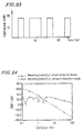
- Figure 2 shows characteristics of the receiving power and the noise power in the IMDD method of 100 MHz.
- the power of the signal beam light source is 100 mW
- a light emission angle is ⁇ 60 degrees
- the radius of the light receiving element is 5 mm
- the receiving frequency band width is 100 MHz.
- Figure 3 shows the characteristics of the signal power and the noise power in the coherent detection of 100 Mbit/s.
- the transmission light source is a semiconductor laser diode (LD) adjusted so as to have a power of 100 mW, an amplitude of 10 MHz, and a light emission angle of ⁇ 60 degrees.
- the light receiving element has a radius of 2 mm
- the receiving frequency band width is 100 MHz.
- ⁇ denotes the demodulated signal power
- ⁇ denotes the noise power.
- At least one of a beat signal intensity, a beat signal frequency and a noise current intensity is detected by the detection means as the coherent light detection state.
- the spatial coherent light transmission apparatus includes: a first light receiving means for receiving and converting the mixed first and second coherent lights into an electric signal; a control signal outputting means for outputting a control signal in accordance with a value of the electric signal converted by the first light receiving means; a direct detection means for performing a direct detection by using the electric signal; and a switching means for switching the direct detection performed by the direct detection means and the coherent detection, in response to the control signal.
- the light receiver means includes: a locally oscillated beam generating means for generating a locally oscillated beam for the coherent detection; and an oscillation frequency switching means for switching an oscillation frequency of the locally oscillated beam generating means in response to the control signal.
- the light receiver means includes a transmitting means for transmitting a control data signal to the light transmitter means in response to the control signal: and the light transmitter means includes a receiving means for receiving the control data signal transmitted from the transmitting means and a modifying means for modifying a modulation method in response to the control data signal received by the receiving means.
- the spatial coherent light transmission apparatus further includes an aperture means for limiting incident light, disposed on the front face of the light receiver means.
- control means includes: a control signal transmission section, disposed in the light receiver means, for transmitting a control signal intensity-modulated in accordance with the information of the state detected by the detection means; a control signal light receiving section, disposed in the light transmitter means, for receiving the control signal; and a control section, disposed in the light transmitter means, for controlling transmission of the data signal by performing a direct detection of a photocurrent received by the control signal light receiving section.
- At least one of a beat signal intensity, a beat signal frequency and a noise current intensity is detected by the detection means as the coherent light detection state.
- the light receiver means includes: a locally oscillated beam generating means for generating a locally oscillated beam for the coherent detection; and an oscillation frequency switching means for switching an oscillation frequency of the locally oscillated beam generating means in response to the control signal.
- the light receiver means includes a transmitting means for transmitting a control data signal to the light transmitter means in response to the control signal
- the light transmitter means includes a receiving means for receiving the control data signal transmitted from the transmitting means and a modifying means for modifying a modulation method in response to the control data signal received by the receiving means.
- the light receiver means includes: a light amount adjustment means for adjusting a light amount input to the first light receiving means; a maximum value detection means for detecting a maximum value of the beat signal supplied from the first light receiving means; and a light amount control means for controlling the light amount adjustment means in response to an output signal from the maximum value detection means.
- the light receiver means includes: a second light receiving means disposed adjacent to the first light receiving means; a phase difference detection means for detecting a phase difference between a signal from the first light receiving means and a signal from the second light receiving means; a phase inversion means, connected to one of the first light receiving means and the second light receiving means, for inverting a phase of the signal from the connected light receiving means in response to an output signal of the phase difference detection means; and an addition means for adding the signal of which phase is inverted by the phase inversion means and the signal of the other of the first light receiving means and second light receiving means.
- the spatial coherent light transmission apparatus further includes an aperture means for limiting incident light, disposed on the front face of the light receiver means.
- a spatial coherent light transmission apparatus includes: a light transmitter means for emitting a data signal as first coherent light, the light transmitter means including a detection means for detecting a coherent light transmission state; a light receiver means for emitting second coherent light having a wavelength little different from that of the first coherent light, mixing and receiving the first and second coherent light, and performing a coherent detection of the data signal; and a control means for controlling at least one of the light transmitter means and the light receiver means based on information of the state detected by the detection means.
- the light transmitter means includes a first detection section for detecting a coherent light transmission state, and a signal transmission sectian for transmitting a control signal of information of the state detected by the first detection section as a light signal obtained by intensity-modulating the data signal;
- the light receiver means includes a signal receiving section for receiving the light signal, a second detection section for detecting a coherent light transmission state and a coherent light detection state from the control signal and the data signal of the light signal received by the signal receiving section, and a wavelength tuning section for controlling a wavelength of the second coherent light based on information of the state detected by the second detection section so as to attain a wavelength tuning;
- the detection means includes the first and second detection sections; and the control means includes the signal transmission section and the wavelength tuning section.
- At least one of a beat signal intensity, a beat signal frequency and a noise current intensity is detected by the detection means as the coherent light detection state.
- a temperature and an oscillation frequency is detected by the detection means as the coherent light transmission state.
- one unit serves as the light transmitter means for emitting a light signal as the first coherent light, as a means for generating the second coherent light, and as the control signal transmission section for transmitting the control signal, and another unit serves as a means for receiving the first and second coherent lights and as a control signal light receiving section for receiving the control signal, whereby the light transmitter means serves also as the light receiver means.
- the spatial coherent light transmission apparatus includes: a receiving section including a means for receiving the first and second coherent lights, the means serving also as a control signal light receiving section for receiving the control signal; a filter section for separating the signal received by the receiving section into the control signal and a beat signal; a control signal detection section for performing a direct detection of the control signal separated by the filter section; and a beat signal detection section for performing the coherent detection of the beat signal separated by the filter section.
- the light receiver means further includes a control signal transmission section for transmitting a second control signal intensity-modulated in accordance with information of the state detected by the detection means; and the light transmitter means includes a control signal light receiving section for receiving the second control signal, and a control section for controlling transmission of the data signal by performing a direct detection of a photocurrent received by the control signal light receiving section.
- data transmission is performed while the coherent detection state is confirmed by the light receiving means, e.g., at the time of starting communication.
- the information or non-detection is transmitted from the control signal transmission section to the control signal receiving section, so that the transmission of the data light signal is controlled by the control section. Accordingly, even if the beat signal is not detected, the loss of data at the time of beat signal non-detection can be prevented by resending the same data signal.
- the wavelength tuning section controls the wavelength of the second coherent light so as to obtain the wavelength tuning on the basis of the detection state information detected by the detection section. Accordingly, even if wavelength deviation arises, wavelength tuning is easily attained and the data transmission at a high speed is assured.
- each of the transmission side and the receiving side uses, for example, a semiconductor laser, whereby the beat signal can be detected within the range of temperatures at which the semiconductor laser is operable.
- the receiving section detects the beat signal detection state and controls the oscillation wavelength of the receiving side itself.
- the beat signal can be detected without changing the wavelength on the transmission side.
- a plurality of receiving sides can be provided with respect to one transmission side, and applications such as a local area network become possible.
- the receiving section attempts to perform wavelength tuning by paying attention only to the beat signal, and if the receiving and transmission sides are respectively provided with lasers, only the beat signal frequency, i.e. the difference in wavelength between the two lasers can be detected. In the case where a wavelength deviation arises in such a situation, there is no clue for knowing whether to increase or reduce the wavelength of the locally oscillated beam. However, the wavelength tuning on the receiving side can be performed more simply by causing the transmission side to transmit the data on the wavelength of the transmission side itself.
- the transmission and receiving sides mutually monitor each other's state.
- information such as the necessity of resending data, a laser failure, etc. are obtained, and both sides can be most appropriately controlled by using such information.
- mutual monitoring has been realized for the first time by using the light intensity modulation and the direct detection technique in combination, which has been impossible even in a bi-directional coherent light transmission apparatus if neither wavefront alignment nor wavelength tuning is attained.
- the receiving side can detect the temperature and oscillation frequency of the oscillation side with a high accuracy. So, in the case where the beat signal cannot be detected, the user can find that a wavefront deviation has occurred. This is useful as a clue for determining the process of wavelength tuning and wavefront alignment.
- control signal transmission section may be used as the control signal transmission section and also as the coherent light signal transmission section.
- a semiconductor laser may be used as the control signal transmission section and the coherent light signal transmission section, whereby the number of times of using the semiconductor laser can be reduced, and the apparatus can be fabricated at a lower cost.
- control signal transmission section may be used as the control signal transmission section and as the coherent light signal transmission section. This makes the circuit configuration simpler, and the apparatus can be fabricated to be smaller and more lightweight.
- the locally oscillated beam generating means On the light receiving section, the locally oscillated beam generating means generates the locally oscillated beam for performing the coherent detection.
- the signal beam transmitted from the light transmission section and the locally oscillated beam supplied from the locally oscillated beam generating means are mixed so as to be supplied to the light receiving means.
- the light receiving means receives the mixed signal beam and converts it into an electric signal.
- the electric power value of the converted electric signal obtained by the light receiving means is compared with a predetermined value by the control signal outputting means, and a control signal in accordance with the result of the comparison is output.
- the signal subjected to the direct detection by the direct detection means and the signal subjected to the coherent detection by the coherent detection means are input to the switching means, and one of the signals is output in response to the control signal output from the control signal outputting means. Also, the oscillation frequency of the locally oscillated beam generating means is switched by the oscillation frequency switching means in response to the control signal output from the control signal outputting means.
- the light receiving section may further include the transmission means
- the light transmission means may further include the receiving means and the modifying means.
- the transmission means transmits data to the transmission section in accordance with the control signal from the control signal outputting means so as to be sent to the receiving means provided in the light transmission section.
- the modifying means modifies the modulation method in accordance with the data received by the receiving means.
- the light transmission section includes light amount control means, maximum value detection means and control means
- the maximum value detection means detects the maximum value of the beat signal supplied from the light receiving means.
- the control means controls the light amount control means so as to control the light mount of the light to be input to the light receiving means.
- the light transmission section further includes second light receiving means, phase difference detection means, phase inversion means and addition means
- the phase difference between the signal outputs from the first and second light receiving means is detected by the phase difference detection means and sent to the phase inversion means.
- the phase inversion means is connected to either one of the first and second light receiving means.
- This phase inversion means inverts the phase in response to the output from the phase difference detection means.
- the signal passed through the phase inversion means and the signal not passed through the phase inversion means are added to each other by the addition means.
- the wavefront of the incident light is converted so as to be aligned with the wavefront of the locally oscillated beam.
- the incident light is controlled by the aperture means, which allows the detection of the maximum value of the beat signal.
- the present invention described herein makes possible the advantages of (1) providing a spatial coherent light transmission apparatus capable of performing a high speed communication and preventing the loss of data, even in the case where the beat signal is not detected or in the case where the beat signal cannot be detected; and (2) providing a spatial coherent light transmission apparatus capable of a stable receiving operation regardless of whether the communication distance is long or short.
- Figure 1 is a diagram showing the configuration of a beat signal detection device for use in a conventional optical communication system.
- Figure 2 is a graph showing the characteristics of the receiving power and the noise power in the IMDD method.
- Figure 3 is a graph showing the characteristics of the signal power and the noise power in coherent detection.
- Figure 4 is a block diagram showing the spatial light transmission apparatus of Example 1 of the present invention.
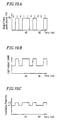
- Figure 5A is a waveform chart showing a data pulse in the main portions of the apparatus as shown in Figure 4 .
- Figure 5B is a waveform chart showing a signal beam oscillation frequency in accordance with 1 or 0 of the data in the main portions of the apparatus as shown in Figure 4 .
- Figure 6A is a waveform chart showing a beat signal obtained when wavefront alignment or wavelength tuning is attained, and when a wavefront deviation or wavelength deviation arises, in the main portions of the apparatus as shown in Figure 4 .
- Figure 6B is a waveform chart showing the light intensity of the control signals in the main portions of the apparatus as shown in Figure 4 .
- Figure 7 is a block diagram showing the configuration of the spatial light transmission apparatus of Example 2 of the present invention.
- Figure 8A is a waveform chart showing a current excited in the light receiving element 35 , in the main portions of the apparatus as shown in Figure 7 .
- Figure 8B is a waveform chart showing a beat signal immediately after an AGC circuit 62a , in the main portions of the apparatus as shown in Figure 7 .
- Figure 9 is a waveform chart showing the control signal in the spatial light transmission apparatus shown in Figure 7 (light intensity modulated by an external modulator 23 ).
- Figure 10 is a block diagram showing the spatial light transmission apparatus of Example 3 of the present invention.
- Figure 11 is a block diagram showing the spatial light transmission apparatus of Example 4 of the present invention.
- Figure 12 is a block diagram showing the spatial light transmission apparatus of Example 5 of the present invention.
- Figure 13 is a timing diagram in the case where data transmission is performed by using the spatial light transmission apparatus shown in Figure 12 .
- Figure 14 is a block diagram showing the configuration of the light transmission section in the spatial light transmission apparatus of Example 6 of the present invention.
- Figure 15 is a diagram showing the transmission characteristics of a light filter in the spatial light transmission apparatus shown in Figure 14 .
- Figure 16 is a block diagram showing the light transmission section in the spatial light transmission apparatus of Example 7 of the present invention.
- Figure 17 is a block diagram showing the transmission section in the spatial light transmission apparatus of Example 8 of the present invention.
- Figure 18 is a block diagram showing the receiving section in the spatial light transmission apparatus of Example 8 of the present invention.
- Figures 19A through 19C are diagrams for explaining the modulation method for use in Example 8 of the present invention.
- Figure 20 is a graph showing one example of actually measured values in Example 8 of the present invention.
- Figure 24 is a graph showing one example of actually measured values in Example 9 of the present invention.
- Figure 25 is a block diagram showing the spatial light transmission apparatus of Example 10 of the present invention.
- Figure 26 is a graph showing one example of actually measured values in Example 10 of the present invention.
- Figure 27 is a block diagram showing the spatial light transmission apparatus of Example 11 of the present invention.
- Figure 28 is a block diagram showing the spatial light transmission apparatus of Example 12 of the present invention.
- a data source 21 which generates data to be transmitted, is connected to a data storage 22 so that the data from the data source 21 can be temporally stored in the data storage 22 .
- This data storage 22 is connected to an LD driver 23 , which is connected to a transmission side LD 24 .
- This transmission side LD 24 is controlled for drive so as to generate a light signal in accordance with the data from the data storage 22 by the LD driver 23 .
- a light receiving element 25 which is directly connected to the data storage 22 , is connected to the data storage 22 also via a control circuit 26 so as to receive a control light signal generated from the receiving side, demodulate and output it to the data storage 22 .
- a receiver section is basically configured in the following manner. That is, a light filter 28 and an optical multiplexer/demultiplexer 29 , which is a beam splitter, are disposed so as to be apart from each other by a predetermined interval.
- the light signal from the transmission side LD 24 is input to the optical multiplexer/demultiplexer 29 via a light filter 28 .
- a local oscillator LD 30 for generating a locally oscillated beam a collimator lens 31 , an optical multiplexer/demultiplexer 32 , which is a beam splitter, and a diffusion micro lens array 33 which is a light diffusion element are provided.
- the locally oscillated beam from the local oscillator LD 30 passes through the collimator lens 31 and the optical multiplexer/demultiplexer 32 and is diffused by the diffusion micro lens array 33 , whereby diffusion plane waves are generated thereby and input to the optical multiplexer/demultiplexer 29 .
- a light receiving element 35 is provided so as to face the optical multiplexer/demultiplexer 29 via a collective lens 34 .
- the signal beam and the diffused plane waves are mixed by the optical multiplexer/demultiplexer 29 so as to be input to the light receiving element 35 via the collective lens 34 .
- a current-voltage conversion circuit (hereinafter, referred to as "I-V circuit") 36 to which the light receiving element 35 is connected, is connected to a high-pass filter 37 which is a high frequency pass filter.
- the high-pass filter 37 is connected to a band pass filter 38 which is an intermediate frequency pass filter.
- the band pass filter 38 is connected to a beat signal demodulation circuit 42 , via a frequency-voltage conversion circuit (hereinafter, referred to as "f-V circuit”) 39a and a comparator 40a .
- f-V circuit frequency-voltage conversion circuit
- an output terminal 41 is connected to this beat signal demodulation circuit 42 .
- the I-V circuit 36 , high-pass filter 37 , band pass filter 38 , f-V circuit 39a , comparator 40a and beat signal demodulation circuit 42 constitute a beat signal detection circuit 43 for detecting a beat signal.
- a mark ratio detection circuit 44 to which the beat signal demodulation circuit 42 is connected, detects a mark ratio of the detected beat signal.
- the mark ratio indicates the ratio of the number of bits of 0 or bits of 1 with respect to the total number of bits.
- An f-V circuit 39b to which the output terminal of the high-pass filter 37 is connected, is connected to one of the input terminals of a comparator 40b . To the other input terminal, the output terminal of the mark ratio detection circuit 44 is connected.
- the f-V circuit 39b and the comparator 40b constitute a wavelength tuning circuit 45 for performing the wavelength tuning on the basis of the beat signal.
- an envelope detection circuit 46 to which the output terminal of the band-pass filter 38 is connected, is connected to a comparator 40c .
- the output terminal of the comparator 40c and the f-V circuit 39b are connected to a discrimination circuit 48 so as to discriminate among the emission intensity of the local oscillator LD 30 , the beat signal intensity and the beat signal frequency.
- the output terminal of a temperature controller 47 to which the output terminal of the comparator 40b is connected, and that of the discrimination circuit 48 are connected to the local oscillator LD 30 .
- the discrimination circuit 48 is connected to a light shutter 50 using a liquid crystal plate via a control circuit 49 . By the output from the discrimination circuit 48 , a control signal is generated from the control circuit 49 so that the light shutter 50 is controlled to be turned ON or OFF.
- the data source 21 On the transmission side, the data source 21 generates a group of pulses (equivalent to 80 Kbits) each having a time length of 0.4 msec every 0.5 msec as shown in Figure 5A .
- the data of the group of pulses is stored in the data storage 22 .
- the data drives the transmission side LD 24 , which is a semiconductor laser, through the LD driver 23 .
- the drive current of the transmission side LD 24 is changed in accordance with the value of the data, i.e. 1 or 0.
- the light is oscillated at an oscillation frequency of ⁇ 1 or ⁇ 2 in accordance with the data.
- a beat signal is excited in the light receiving element 35 by overlapping the received signal beam with the diffusion plane waves of a wavelength of ⁇ 3, emitted by the local oscillator LD 30 or the like, (where ⁇ 3 denotes the wavelength of the beam having a frequency of ⁇ 3, and the same relationship is established for wavelengths such as ⁇ 1 and ⁇ 2).
- the frequencies of this beat signal are
- the beat signal is set so that
- wavelength tuning will be described.
- the signal generated in the light receiving element 35 is converted from a current component to a voltage component by the I-V circuit 36 . Thereafter, only the beat signal components are taken out by the high pass filter 37 .
- the output of the high pass filter 37 is applied to the f-V circuit 39b , where an average frequency thereof is converted into a voltage.
- the output from the f-V circuit 39b and a predetermined voltage are compared with each other by the comparator 40b .
- the temperature controller 47 is controlled and the output of the temperature controller 47 is used for controlling the frequency of the local oscillator LD 30 so as to attain wavelength tuning.
- the demodulation of the beat signal will be described hereinafter.
- the band-pass filter 38 transmitting only a beat signal excludes noise components from the other output of the high-pass filter 37 . Thereafter, the frequency thereof is converted into a voltage by the f-V circuit 39a .
- the comparator 40a demodulates the voltage into data of 1 or 0.
- the amplitude thereof is detected by an envelope detection circuit 46 .
- the detected amplitude is subjected to a threshold value processing by the comparator 40c .
- the resultant signal is input to the discrimination circuit 48 .
- the beat signal demodulation circuit 42 receives data of the amount of 80 Kbits (0.4 msec)
- the light shutter 50 is driven by a control signal corresponding to the termination of receiving of the group of data, so that the data is transmitted to the transmission side 26 .
- this light signal is received by the light receiving element 25 , followed by the transmission of the next data.
- the light shutter 50 is turned ON or OFF through the discrimination circuit 48 by the control circuit 49 , which is a control signal generating circuit.
- This ON/OFF signal as the control signal changes the intensity of the light from the local oscillation laser 30 in the manner as shown in Figure 6B .
- the information to be transmitted has been encoded.
- the receiving side demodulates the encoded signal by a demodulation circuit (not shown), thus knowing the information on the receiving side (in this case, the loss of data caused by the wavelength deviation). Furthermore, the control circuit 26 controls the transmission of the light signal based on the information.
- the information to be transmitted includes the intensity of the locally oscillated beam obtained e.g. by monitoring the current of the light receiving element (not shown) attached to the local oscillation laser 30 which is a semiconductor laser, the beat signal frequency discrimination state, the beat signal amplitude detection state and the like.
- Example 1 the data transmission of 160 Mbps is possible in the case where there is no loss of data, and the data transmission of 80 Mbps is possible in the case where the loss of data arises at a ratio of 1/2.
- FIG. 7 is a block diagram showing the spatial coherent light transmission apparatus of Example 2.
- the components corresponding to those in Example 1 are denoted by the same reference numerals.
- a band pass filter 38b to which the I-V circuit 36b is connected, is connected to an automatic gain control (AGC) circuit 62a , an f-V circuit 39d , a comparator 40e and a demodulation circuit 42a , for monitoring the control signal.
- a high pass filter 37a to which the I-V circuit 36b is connected, is connected to a band pass filter 38c , an AGC circuit 62b , a phase detector 63 , a comparator 40f and a demodulation circuit 42b , for detecting the beat signal by means of coherent detection.
- a low pass filter 64 to which an I-V circuit 36b is connected, an f-V circuit 39e to which the high pass filter 37a is connected and a comparator 40h are connected to a discrimination circuit 48a .
- the discrimination circuit 48a is connected to a light modulator 66 intermediately provided between a collimator lens 31 and an optical multiplexer/demultiplexer 32 , whereby the light from the local oscillator LD 30 is modulated by the control circuit 65 on the basis of the output from the discrimination circuit 48a .
- a light signal is first output from a transmission side LD 24 by driving an LD driver 23 while accumulating signals from the data source 21 into the data storage 22 .
- the oscillation wavelength is set at ⁇ 1, and the phase of the transmission light is modulated depending on whether the data is 1 or 0 by using a phase modulator (not shown).
- the light having a wavelength of ⁇ 3 is emitted by the local oscillator LD 30 .
- the amplitude of the emission light is modulated by a light modulator 66 so as to have the form of a sine wave. That is, the conditions of the receiving side are transmitted to the transmission side by modulating the frequency of this sine wave.
- the locally oscillated beam is mixed with the signal beam by an optical multiplexer/demultiplexer 29 so as to be incident onto a light receiving element 35 .
- the frequency transmission band of the high pass filter 37a is 100 MHz or more, while that of the band pass filter 38b is from 100 KHz to 20 MHz, which are sufficient to separate between the two signals having the above-mentioned frequencies.
- the signal passed through the band pass filter 38b passes through the AGC circuit 62a , the f-V circuit 39d and the comparator 40e . Then, the signal is demodulated by the demodulation circuit 42a into the original frequency modulated signal obtained by the light modulator 66 so as to monitor the condition of the receiving side itself.
- the signal passed through a band pass filter 38c (transmission band: 100 to 300 MHz) via the I-V circuit 36b and the high pass filter 37a has been changed so as to have only beat signal components.
- this signal becomes the beat signal of a constant intensity in the AGC circuit 62b .
- the resultant signal is subjected to phase detection by the phase detector 63 , so that the original digital data is demodulated via the comparator 40f and the demodulation circuit 42b .
- the mark ratio is detected by a mark ratio detection circuit 44 .
- the expected average beat frequency and the output from the frequency discrimination circuit are compared by a comparator 40g .
- the wavelength tuning operation is performed for the local oscillator LD 30 by the temperature controller 47 .
- the APC circuit 68 controls the injection current injected from the direct current source 67 so as to have a constant light power by using the current value of the light receiving element (not shown) attached to the local oscillator LD 30 .
- the discrimination circuit 48a drives the control circuit 65 which is the control signal generating circuit.
- the beam oscillated by the local oscillator laser LD 30 is modulated by the light modulator 66 via this control circuit 65 .
- the direct current components excited in the light receiving element 35 by the local oscillator LD 30 can be kept approximately constant by using the APC circuit 68 .
- the components corresponding to an alternating current are removed from the output of the I-V circuit 36b by the low pass filter 64 , whereby the intensity of the background light can be monitored.
- the discrimination circuit 48a informs the transmission side of this condition.
- the data transmitted to the transmission side in such a case includes the beat signal intensity state (with respect to the wavefront alignment), the beat signal frequency state (the information on the wavelength tuning), the state of the local oscillator LD 30 and the background light intensity.
- the frequency of the frequency modulation signal obtained by the light moduletor 66 is changed in accordance with such states.
- the light signal taken out from the optical multiplexer/demultiplexer 32 by the local oscillator LD 30 (the light being loaded with a frequency modulation signal of 1 Mbps by the light modulator 66 ), is received by the light receiving element 25 .
- the received signal is subjected to the current-voltage conversion processing by the I-V circuit 36a .
- a band pass filter 38a having the same characteristics as those of the band pass filter 38b , only signal components are detected from the received signal.
- the signal is subjected to frequency-voltage conversion by the f-V circuit 39c , and the resultant voltage is compared with a predetermined voltage by the comparator 40d so as to be demodulated.
- the control circuit 61 makes judgments with respect to the control of the light signal transmission, such as data transmission, data resending, the cancellation of data transmission etc.
- Example 2 permits the receiving side to always inform the transmission side of its states, and to transmit the data also during such informing operation.
- FIG 10 is a block diagram showing a spatial coherent light transmission apparatus of Example 3.
- the components corresponding to those in Examples 1 and 2 are denoted by the same reference numerals.
- the light transmission apparatus of Example 3 is a light transmission/receiving unit in which a transmitter and a receiver are integrated.
- a data storage 22a is connected to a semiconductor laser diode (LD) 30a via an LD driver 23a .
- This semiconductor LD 30a is used as an LD for the transmission side, and also as a local oscillator LD.
- An f-V circuit 39e to which a high pass filter 37a is connected, is connected to a temperature controller 47 through a comparator 40g .
- An envelope detection circuit 46 to which a band pass filter 38c is connected, is connected to a discrimination circuit 48b through a comparator 40h .
- the temperature controller 47 and discrimination circuit 48b are connected to the LD 30a . Furthermore, a control circuit 65a , to which the discrimination circuit 48b is connected, is connected to a light modulator 66a intermediately provided between a collimator lens 31 and an optical multiplexer/demultiplexer 32 .
- the data transmission is performed by a Manchester method. Namely, the signal beam is changed from a high to low level when the signal in the data source is 1, and from a low to high level when it is 0.
- a current is injected from the LD driver 23a so as to cause the oscillation wavelength thereof to be ⁇ 1 or ⁇ 2 depending on whether the signal beam is in the high or low levels.
- the light modulator 66a provides no processing, so that the light having a wavelength of ⁇ 1 or ⁇ 2 is emitted over a given solid angle through the optical multiplexer/demultiplexer 32 .
- the semiconductor LD 30a oscillates light of a wavelength ⁇ 3 which is little different from the signal beam frequencies of ⁇ 1 and ⁇ 2.
- the oscillated light is mixed with the signal beam propagated from the transmission side by an optical multiplexer/demultiplexer 29 and is received by the light receiving element 35 .
- the locally oscillated beam from the semiconductor LD 30a has been subjected to frequency modulation by a light moduletor 66a .
- the beat signal is demodulated by a demodulation circuit 42b , while the control signal for controlling the receiving side itself, obtained by the light modulator 66a , is demodulated by a demodulation circuit 42a .
- the average frequency of the beat signal is constant, i.e. (
- the mark ratio detection circuit 44 as employed in Examples 1 and 2 is unnecessary.
- the light receiving element 35b is provided for receiving and demodulating the control signals (including the data on the transmission wavelength, on the trouble of the transmission side LD, etc.) emitted from the transmission side.
- control signals including the data on the transmission wavelength, on the trouble of the transmission side LD, etc.
- the light filter 28b is designed to transmit light having the wavelength of the control signal (a center wavelength: ⁇ 4) generated from the transmission side.
- the light filter 28a is designed to cut off light having a wavelength of ⁇ 4.
- the parallel beam is caused to be incident onto the diffraction grating plate 83 with a pitch of ⁇ at an incident angle of ⁇ i .
- the apparatus of Example 7 is arranged so that the pitch of the light receiving element in the form of an array is set at 20 ⁇ m and that the oscillation wavelength of the laser serving as the transmission side LD 24b can be detected with accuracy on the order of about 0.1 nm.
- the electric capacity of each light receiving element can be significantly reduced.
- a response speed of about 10 GHz can be realized.
- the detected wavelength is converted into a digital signal by the LD driver 23d , and is transmitted to the receiving side as wavelength information.
- the method for transmission is not specifically described, but it can be easily carried out on the basis of techniques described in the foregoing examples.
- wavelength tuning can be attained with an accuracy of ⁇ 0.1 nm.
- the beat signal current is not detected if the wavefront alignment is not attained. If so, first, the wavefront alignment is attempted. When the wavefront alignment is attained, the beat signal current is detected. Then, the wavelength tuning is performed by controlling the local oscillator LD so that a predetermined relationship holds between the frequency of the signal beam and that of the locally oscillated beam. In this way, the process for the wavefront alignment and the wavelength tuning can be determined.
- the spatial coherent light transmission apparatus of the foregoing examples include the following structures:
- Example 8 of the present invention With reference to Figures 17 and 18 , a spatial light transmission apparatus of Example 8 of the present invention will be described.
- an incident signal beam passes through the light filter 105 for reducing the background light.
- the passed light is incident onto the PD 109 via the optical multiplexer 106 .
- the light receiving face is of a diameter of 2 mm, and the amplification magnification is 100.
- the electric power value of -45 dBm is equivalent to the case where the distance between the transmission section and the receiving section is about 0.7 m, though varying depending on the intensity of the background light or the like.
- the oscillation wavelength of the locally oscillated beam is
- is detected.
- the alternating current part obtained by subtracting the direct current part from the output of the avalanche PD 109 , is demodulated into an original digital signal via the AGC 111 by the narrow-band filter 112 with a transmission band width of 1 MHz and the DEM 114 .
- the pulse part similarly obtained by subtracting the direct current part from the output of the PD 109 is demodulated into an original digital signal via the AGC 111 by the wide-band filter 113 with a transmission band width of 200 MHz and the DEM 126 .
- the output of the electric power comparator 110 is connected to the reversal input terminal of the logic circuit 116 and one input terminal of the logic circuit 117 .
- the output of the DEM 114 is connected to the other input terminal of the logic circuit 116 .
- the output of the DEM 126 is connected to the other input terminal of the logic circuit 117 .
- the output from the logic circuits 116 and 117 are both input to the logic circuit 118 .
- the electric signal arising due to the intensity modulation of the transmission light is demodulated by the circuit composed of the AGC 111 , the wide-band filter 113 and the DEM 126 .
- a digital signal of 0 has been output from the electric power comparator 110 , and the logic circuit 116 is turned ON by the signal from the DEM 126 .
- the output from the DEM 126 is connected to the other input terminal of the logic circuit 117 .
- the data signal is output from the logic circuit 118 .
- the beat signal caused by the locally oscillated beam and the signal beam is demodulated by the AGC 111 , the narrow-band filter 112 and the DEM 114 .
- a digital signal of 1 has been output from the electric power comparator 110 , and the logic circuit 117 is turned ON by the signal from the DEM 114 .
- the data signal is output from the logic circuit 118 .
- the transmission side can transmit the data regardless of the conditions of the receiving side, while the receiving side can select the most appropriate receiving method.
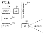
- Example 9 of the present invention With reference to Figures 21 and 22 , the spatial light transmission apparatus of Example 9 of the present invention will be described.
- Figure 21 is a block diagram showing the light transmission section of the spatial light transmission apparatus of Example 9, and Figure 22 is a block diagram showing the light receiving section thereof.
- Example 9 data transmission is performed at 100 Mbit/s, and similar to Example 8, a semiconductor laser (LD) 301 is used as the transmission light source.
- the intensity of light emission is 80 mW and the light is emitted in space over an angle of ⁇ 30°.
- the transmission side is composed of the semiconductor laser 301 , a light receiving element 309c , an automatic gain controller 305 , an amplifier 304 , a filter 303 and a modulator 302 .
- the semiconductor laser 301 transmits a signal beam.
- the automatic gain controller 305 is connected to the light receiving element 309c and adjusts the level of an input signal therefrom.
- the amplifier 304 amplifies the signal input from the automatic gain controller 305 .
- the filter 303 filters the signal input from the amplifier 304 .
- the modulator 302 modulates the signal transmitted from the semiconductor laser 301 by using the signal input from the filter 303 .
- the light filter 320 cuts off the background light.
- the coherent detection light receiving element 309a receives the light transmitted through the light filter 320 .
- the electric power comparator 310 is connected to the light receiving element 309a .
- the automatic gain controller 311 adjusts the level of the signal input from the electric power comparator 310 .
- the filter 312 filters the signal input from the automatic gain controller 311 .
- the demodulator 313 demodulates the signal input from the filter 312 .
- the local oscillator light source laser 308 generates the locally oscillated beam.
- the lens 307 converges the light output from the local oscillator light source laser 308 .
- the optical multiplexer 306 mixes the light input from the light filter 320 and the light input from the lens 307 .
- the light receiving element 309a receives the light from the optical multiplexer 306 .
- the automatic gain controller 315 receives the signal from the coherent detection light receiving element 309a .
- the filter 316 filters the signal input from the automatic gain controller 315 .
- the demodulator 317 demodulates the signal supplied from the filter 316 .
- the switch 314 receives a switching signal from the electric power comparator 310 and outputs either the signal from the demodulator 313 or the signal from the demodulator 317 .
- the modulator 323 receives and demodulates the output from the electric power comparator 310 .
- the feedback light laser 324 performs the output of the feedback light modulated by the modulator 323 .
- the outputs of the coherent detection light receiving element 309a and the direct detection light receiving element 309b are amplified as high as one hundred times by an avalanche photodiode.
- the signal beam transmitted from the semiconductor laser 301 of the transmission section transmits through the light filter 320 cutting off the background light, and then is incident onto the coherent detection light receiving element 309a and the direct detection light receiving element 309b .
- the electric power comparator 310 supplies a control signal to the switch 314 so as to perform the direct detection.
- the output of the comparator 310 is modulated into a feedback signal by the modulator 323 so as to drive the feedback light laser 324 .
- This data can be efficiently transmitted by a low speed transmission. Accordingly, the transmission side can demodulate it by direct detection with a satisfactory S/N ratio.
- the level of the output from the electric power comparator 310 is adjusted by the automatic gain controller 311 , filtered by the filter 312 , and demodulated by the demodulator 313 . Thereafter, the demodulated signal is supplied to the switch 314 .
- the light output from the local oscillator light source laser 308 is converged on the optical multiplexer 306 by the lens 307 .
- the optical multiplexer 306 mixes the light input from the lens 307 and the light input from the light filter 320 so as to be supplied to the light receiving element 309a .
- the signal output from the light receiving element 309a undergoes the level adjustment by the automatic gain controller 315 , is filtered by the light filter 316 , and is demodulated by the demodulator 317 .
- the demodulated signal is supplied to the switch 314 .
- the light receiving portion of the coherent detection light receiving element 309a is sized to have a diameter of 3.5 mm, while that of the direct detection light receiving element 309b is sized to have a diameter of 10 mm.
- Figure 24 shows one example of actually measured values of the S/N ratio. As is apparent from Figure 24 , it is most appropriate to switch between direct detection and coherent detection when the communication distance is about 2 m.
- Figure 25 is a block diagram showing the light receiving section of the spatial light transmission apparatus of Example 10, where the transmission side thereof is the same as that of Example 8 as shown in Figure 17 .
- the receiving section is composed of a light filter 505 , a local oscillator light source laser (LD) 508 , a lens 506 , an optical multiplexer (BS) 507 , a light receiving element 509a , a light receiving element 509b , an automatic gain controller (AGC) 511 , an automatic gain controller (AGC) 515 , a phase comparator 512 , an electric filter 513 , an electric filter 516 , a phase inverter 517 and a demodulator 514 .
- LD local oscillator light source laser
- BS optical multiplexer
- AGC automatic gain controller
- AGC automatic gain controller
- AGC automatic gain controller
- the lens 506 converges the light from the local oscillator light source laser 508 .
- the optical multiplexer 507 mixes the light transmitted through the light filter 505 and the light transmitted through the lens 506 .
- the light receiving element 509a receives the light from the optical multiplexer 507 .
- the light receiving element 509b is incorporated into the center portion of the light receiving element 509a .
- the automatic gain controller 511 adjusts the level of the signal supplied from the light receiving element 509a .
- the automatic gain controller 515 adjusts the level of the signal supplied from the light receiving element 509b .
- the phase comparator 512 compares the phase of the signal supplied from the automatic gain controller 511 and that of the signal supplied from the automatic gain controller 515 .
- the electric filter 513 filters the signal from the automatic gain controller 511 .
- the electric filter 516 filters the signal from the automatic gain controller 515 .
- the phase inverter 517 inverts the phase of the signal supplied from the electric filter 516 .
- the demodulator 514 demodulates the signals supplied from the electric filter 513 and the phase inverter 517 .
- the light receiving element 509b has a diameter of 800 ⁇ m.
- the light receiving element 509a has the light receiving element 509b incorporated at its center portion, and has an outer diameter of 4 mm.
- the two light receiving elements are coaxially disposed, but the same effects can be obtained even if they are disposed in different manners.
- the beat signal caused by the beam from the local oscillator light source laser 508 and the signal beam incident from the transmission section is processed by the automatic gain controller 511 and the electric filter 513 , while the beat signal from the light receiving element 509b is processed by the automatic gain controller 515 and the electric filter 516 .
- the beat signals from the automatic gain controllers 511 and 515 are simultaneously input to the phase comparator 512 so that the phases thereof are compared with each other.
- Example 10 by detecting the power of the light source of the signal beam is detected, the optimum coherent detection free from fluctuations in the light intensity of the transmission light source was realized without necessity of switching the detection mode.
- Figure 26 shows the effects obtained by applying Example 10 in practice. As is apparent from this graph, the S/N ratio of 0 dB was assured when the distance between the transmission section and the receiving section is up to 30 m.
- the light receiving section is composed of a light filter 601 , an aperture 602 , a local oscillator light source laser (LD) 609 , a lens 610 , an optical multiplexer 612 , an automatic gain controller 606 , a light receiving element 603 , an electric filter 607 , a demodulator 608 , a peak detector 605 and a control circuit 604 .
- LD local oscillator light source laser
- the incident signal beam After passing through the light filter 601 , the incident signal beam passes through the aperture 602 and is incident onto the light receiving element 603 , which has a diameter of 1 cm.
- the beat signal caused by the beam from the local oscillator laser 609 and the incident signal beam is detected by the light receiving element 603 and is processed by the automatic gain controller 606 and the electric filter 607 , so as to be demodulated into an original digital signal by the demodulator 608 .
- the aperture 602 is variable by the control circuit 604 , and the maximum value of the intensity of the beat signal is detected by the peak value detector 605 .
- the aperture 602 is controlled so as to maximize the beat signal intensity.
- Varying the aperture 602 equivalently changes the size of the light receiving element, thus always allowing the stable beat signal detection.
- the data transmission is stably performed regardless of the communication distance.
- Figure 28 is a block diagram showing the light receiving section of the spatial light transmission apparatus of Example 12, the transmission side thereof being the same as that of Example 8 as shown in Figure 17 .
- the lens 909 collects the light from the local oscillator light source laser 908 .
- the optical multiplexer 903 mixes the light transmitted through the light filter 902 and that from the light passed through the lens 909 .
- the light receiving element 904 converts the beat signal supplied from the optical multiplexer 903 into an electric signal.
- the automatic gain controller 905 adjusts the level of the signal supplied from the light receiving element 904 .
- the electric filter 906 filters the signal from the automatic gain controller 905 .
- the demodulator 907 demodulates the signal supplied from the electric filter 906 .
- a collective lens 901 is disposed in front of the light filter 902 .
- the focal length of this collective lens 901 is 10 m. In the case where the distance between the transmission light source and the receiving device is 10 m or more, by means of this lens, the received signal beam becomes apparent spherical waves from the point corresponding to the distance of about 10 m.
- a fixed focus lens is used for the lens 901 in Example 12, but it can be replaced with a variable focus lens. In such a case, more desirable effects are obtainable by controlling the variable focus lens in accordance with the intensity of the received signal or the detected beat signal.
- the intensity of the beat signal can be sufficiently obtained in long distance transmission, by providing a collective lens with the receiving side. As a result, an optimum receiving operation is assured for a predetermined range of the distance.
Landscapes
- Physics & Mathematics (AREA)
- Electromagnetism (AREA)
- Engineering & Computer Science (AREA)
- Computer Networks & Wireless Communication (AREA)
- Signal Processing (AREA)
- Optical Communication System (AREA)
Applications Claiming Priority (6)
| Application Number | Priority Date | Filing Date | Title |
|---|---|---|---|
| JP301748/93 | 1993-12-01 | ||
| JP30174893 | 1993-12-01 | ||
| JP5301748A JP2904696B2 (ja) | 1993-12-01 | 1993-12-01 | 空間光伝送装置 |
| JP41508/94 | 1994-03-11 | ||
| JP06041508A JP3075909B2 (ja) | 1994-03-11 | 1994-03-11 | 空間コヒーレント光伝送装置 |
| JP4150894 | 1994-03-11 |
Publications (2)
| Publication Number | Publication Date |
|---|---|
| EP0656699A1 true EP0656699A1 (de) | 1995-06-07 |
| EP0656699B1 EP0656699B1 (de) | 2002-04-17 |
Family
ID=26381148
Family Applications (1)
| Application Number | Title | Priority Date | Filing Date |
|---|---|---|---|
| EP94118884A Expired - Lifetime EP0656699B1 (de) | 1993-12-01 | 1994-11-30 | Einrichtung zur leitungsungebundenen optischen Signalübertragung |
Country Status (3)
| Country | Link |
|---|---|
| US (1) | US5548434A (de) |
| EP (1) | EP0656699B1 (de) |
| DE (1) | DE69430418T2 (de) |
Cited By (2)
| Publication number | Priority date | Publication date | Assignee | Title |
|---|---|---|---|---|
| EP0749219A3 (de) * | 1995-06-14 | 1999-10-27 | Nec Corporation | Räumliche Infrarotübertragungssystem, das in der Lage ist, die Menge von verarbeitenden Datenkommunikationsgeräten während der Kommunikation zu reduzieren |
| EP0951761A4 (de) * | 1996-11-20 | 2005-09-21 | Talking Signs Inc | Signalsender mit automatischer ausgangssteuerung |
Families Citing this family (24)
| Publication number | Priority date | Publication date | Assignee | Title |
|---|---|---|---|---|
| US5717708A (en) * | 1995-11-09 | 1998-02-10 | Mells; Bradley | Method and apparatus of stabilizing a semiconductor laser |
| CA2204829A1 (en) * | 1997-05-08 | 1998-11-08 | Alain Z. Shang | Optical receiver suitable for optical interconnects |
| US6243182B1 (en) * | 1998-07-13 | 2001-06-05 | Optical Scientific, Inc. | Atmospheric turbulence resistant open-air optical communication system |
| US6271944B1 (en) * | 1999-06-30 | 2001-08-07 | Philips Electronics North America Corp. | Laser wavelength control in an optical communication system |
| US6490067B2 (en) * | 2000-05-16 | 2002-12-03 | Airfiber, Inc. | Multi-channel optical transceiver |
| US6771694B1 (en) * | 2000-07-12 | 2004-08-03 | International Business Machines Corporation | Speed negotiation for serial transceivers |
| US6977966B1 (en) * | 2000-11-28 | 2005-12-20 | Tellabs Bedford, Inc. | Bidirectional optical communications having quick data recovery without first establishing timing and phase lock |
| EP1425865A4 (de) * | 2001-04-18 | 2006-08-23 | Texas Instruments Inc | System zur anschaffung und wartung zuverlässiger optischer drahtloser verbindungen |
| US20030016425A1 (en) * | 2001-07-19 | 2003-01-23 | Tan Tun Sein | Polarization diversity receiver with planar waveguide and polarizing beam splitter |
| US6934475B2 (en) * | 2001-08-16 | 2005-08-23 | The Regents Of The University Of California | Free-space optical communications using holographic conjugation |
| JP3999012B2 (ja) * | 2002-03-22 | 2007-10-31 | 富士通株式会社 | 波長可変光フィルタの制御方法および制御装置 |
| US7499653B2 (en) * | 2003-07-14 | 2009-03-03 | Hrl Laboratories, Llc | Multiple wavelength photonic oscillator |
| US7822082B2 (en) * | 2004-01-27 | 2010-10-26 | Hrl Laboratories, Llc | Wavelength reconfigurable laser transmitter tuned via the resonance passbands of a tunable microresonator |
| US20050198636A1 (en) * | 2004-02-26 | 2005-09-08 | International Business Machines Corporation | Dynamic optimization of batch processing |
| US7561813B2 (en) * | 2005-06-09 | 2009-07-14 | Northrop Grumman Corporation | Wide field of view heterodyne receiver |
| DE102006028288A1 (de) * | 2006-06-20 | 2007-12-27 | Siemens Ag | Verfahren und Vorrichtung zum Austausch von Daten |
| JP4531740B2 (ja) * | 2006-12-15 | 2010-08-25 | 富士通株式会社 | コヒーレント光受信機 |
| JP5034770B2 (ja) * | 2007-08-16 | 2012-09-26 | 富士通株式会社 | コヒーレント光受信器および光通信システム |
| US8451224B2 (en) * | 2008-07-23 | 2013-05-28 | Sony Corporation | Mapping detected movement of an interference pattern of a coherent light beam to cursor movement to effect navigation of a user interface |
| US8571419B2 (en) * | 2011-09-01 | 2013-10-29 | Fujitsu Limited | Method and system for flexible optical signal aggregation and transmission |
| JP6058175B2 (ja) * | 2014-02-13 | 2017-01-11 | 三菱電機株式会社 | 光受信器 |
| US10014938B2 (en) * | 2015-10-23 | 2018-07-03 | Calix, Inc. | Optical network terminal wavelength notification |
| JP7621068B2 (ja) * | 2020-06-09 | 2025-01-24 | 株式会社タムロン | 通信装置、光軸方向調整方法、及び、通信システム |
| CN113541812B (zh) * | 2021-07-15 | 2022-06-14 | 苏州大学 | 一种无线光通信数据传输装置及方法 |
Citations (3)
| Publication number | Priority date | Publication date | Assignee | Title |
|---|---|---|---|---|
| JPS62143529A (ja) * | 1985-12-18 | 1987-06-26 | Mitsubishi Electric Corp | 光空間伝搬通信装置 |
| JPH0346839A (ja) * | 1989-07-14 | 1991-02-28 | Nec Corp | 空間光伝送方式 |
| EP0564075A1 (de) * | 1992-02-25 | 1993-10-06 | Nortel Networks Corporation | Optische Übertragung mit FSK-Modulation, Phasen-Kontinuität und geregeltem lokalem Oszillator |
Family Cites Families (2)
| Publication number | Priority date | Publication date | Assignee | Title |
|---|---|---|---|---|
| JPS59140736A (ja) * | 1983-01-31 | 1984-08-13 | Nec Corp | 光ヘテロダイン検波パルス受信方法 |
| JPH05160793A (ja) * | 1991-12-10 | 1993-06-25 | Matsushita Electric Ind Co Ltd | 光空間伝送装置 |
-
1994
- 1994-11-30 US US08/351,224 patent/US5548434A/en not_active Expired - Fee Related
- 1994-11-30 EP EP94118884A patent/EP0656699B1/de not_active Expired - Lifetime
- 1994-11-30 DE DE69430418T patent/DE69430418T2/de not_active Expired - Fee Related
Patent Citations (3)
| Publication number | Priority date | Publication date | Assignee | Title |
|---|---|---|---|---|
| JPS62143529A (ja) * | 1985-12-18 | 1987-06-26 | Mitsubishi Electric Corp | 光空間伝搬通信装置 |
| JPH0346839A (ja) * | 1989-07-14 | 1991-02-28 | Nec Corp | 空間光伝送方式 |
| EP0564075A1 (de) * | 1992-02-25 | 1993-10-06 | Nortel Networks Corporation | Optische Übertragung mit FSK-Modulation, Phasen-Kontinuität und geregeltem lokalem Oszillator |
Non-Patent Citations (4)
| Title |
|---|
| MERCER: "Adaptive coherent optical receiver array", ELECTRONICS LETTERS., vol. 26, no. 18, 30 August 1990 (1990-08-30), STEVENAGE GB, pages 1518 - 1520 * |
| NUSSMEIER ER AL: "A 10.6 mu m Terrestrial Communication Link", IEEE JOURNAL OF QUANTUM ELECTRONICS., vol. 10, no. 2, February 1974 (1974-02-01), NEW YORK US, pages 230 - 235 * |
| PATENT ABSTRACTS OF JAPAN vol. 11, no. 376 (E - 563) 1987 * |
| PATENT ABSTRACTS OF JAPAN vol. 15, no. 187 (E - 1067) 1991 * |
Cited By (2)
| Publication number | Priority date | Publication date | Assignee | Title |
|---|---|---|---|---|
| EP0749219A3 (de) * | 1995-06-14 | 1999-10-27 | Nec Corporation | Räumliche Infrarotübertragungssystem, das in der Lage ist, die Menge von verarbeitenden Datenkommunikationsgeräten während der Kommunikation zu reduzieren |
| EP0951761A4 (de) * | 1996-11-20 | 2005-09-21 | Talking Signs Inc | Signalsender mit automatischer ausgangssteuerung |
Also Published As
| Publication number | Publication date |
|---|---|
| US5548434A (en) | 1996-08-20 |
| DE69430418D1 (de) | 2002-05-23 |
| EP0656699B1 (de) | 2002-04-17 |
| DE69430418T2 (de) | 2002-12-05 |
Similar Documents
| Publication | Publication Date | Title |
|---|---|---|
| EP0656699B1 (de) | Einrichtung zur leitungsungebundenen optischen Signalübertragung | |
| EP0642236B1 (de) | Leitungsungebundenes optisches Übertragungssystem | |
| US5664035A (en) | Bidirectional optically powered signal transmission apparatus | |
| US20020131121A1 (en) | Transceiver, system, and method for free-space optical communication and tracking | |
| RU2172560C1 (ru) | Устройство оптической связи | |
| EP0582998B1 (de) | System zum Durchführen eines Lichtbündels im freien Raum | |
| US5710652A (en) | Laser communication transceiver and system | |
| US20060018661A1 (en) | Alignment system | |
| JP6010696B2 (ja) | 能動的キャリアホッピングを有する波長分割多重化光通信システムを提供する方法および装置 | |
| CN108768516A (zh) | 波长快速可调谐的空间激光通信终端 | |
| US6941076B1 (en) | Tone modulation for out-of-band communication in a free-space optical communication link | |
| JP2001298422A (ja) | ワイヤレス光通信システムにおいて光信号を自動的にトラッキングするための方法および装置 | |
| US20020154364A1 (en) | Signalling system | |
| EP0820162A2 (de) | Übertragungsvorrichtung für optische Signale und Übertragungsverfahren für optische Signale | |
| US6970651B1 (en) | High-sensitivity tracking in free-space optical communication systems | |
| US5602665A (en) | Optical transmitting/receiving apparatus for bidirectional communication systems | |
| RU2174741C1 (ru) | Устройство для атмосферной оптической связи | |
| KR20080066893A (ko) | 광 무선 통신 시스템에서의 파장 대역 분할 다중화 통신시스템, 장치 및 그 방법 | |
| EP1416651B1 (de) | Optischer Empfänger | |
| JP2904696B2 (ja) | 空間光伝送装置 | |
| JP3075909B2 (ja) | 空間コヒーレント光伝送装置 | |
| JPH11234209A (ja) | データ送受信装置 | |
| JP7709942B2 (ja) | 光給電システム、給電装置及び受電装置 | |
| US20250379662A1 (en) | Powered device, optical power feeding system, and power receiving method | |
| JP7844255B2 (ja) | 受電装置、給電装置、光給電システム、受電方法及び光給電方法 |
Legal Events
| Date | Code | Title | Description |
|---|---|---|---|
| PUAI | Public reference made under article 153(3) epc to a published international application that has entered the european phase |
Free format text: ORIGINAL CODE: 0009012 |
|
| AK | Designated contracting states |
Kind code of ref document: A1 Designated state(s): DE FR GB |
|
| 17P | Request for examination filed |
Effective date: 19950831 |
|
| 17Q | First examination report despatched |
Effective date: 19990811 |
|
| GRAG | Despatch of communication of intention to grant |
Free format text: ORIGINAL CODE: EPIDOS AGRA |
|
| GRAG | Despatch of communication of intention to grant |
Free format text: ORIGINAL CODE: EPIDOS AGRA |
|
| GRAH | Despatch of communication of intention to grant a patent |
Free format text: ORIGINAL CODE: EPIDOS IGRA |
|
| REG | Reference to a national code |
Ref country code: GB Ref legal event code: IF02 |
|
| GRAH | Despatch of communication of intention to grant a patent |
Free format text: ORIGINAL CODE: EPIDOS IGRA |
|
| GRAA | (expected) grant |
Free format text: ORIGINAL CODE: 0009210 |
|
| AK | Designated contracting states |
Kind code of ref document: B1 Designated state(s): DE FR GB |
|
| REF | Corresponds to: |
Ref document number: 69430418 Country of ref document: DE Date of ref document: 20020523 |
|
| ET | Fr: translation filed | ||
| PGFP | Annual fee paid to national office [announced via postgrant information from national office to epo] |
Ref country code: DE Payment date: 20021120 Year of fee payment: 9 |
|
| PGFP | Annual fee paid to national office [announced via postgrant information from national office to epo] |
Ref country code: GB Payment date: 20021210 Year of fee payment: 9 |
|
| PGFP | Annual fee paid to national office [announced via postgrant information from national office to epo] |
Ref country code: FR Payment date: 20021217 Year of fee payment: 9 |
|
| PLBE | No opposition filed within time limit |
Free format text: ORIGINAL CODE: 0009261 |
|
| STAA | Information on the status of an ep patent application or granted ep patent |
Free format text: STATUS: NO OPPOSITION FILED WITHIN TIME LIMIT |
|
| 26N | No opposition filed |
Effective date: 20030120 |
|
| PG25 | Lapsed in a contracting state [announced via postgrant information from national office to epo] |
Ref country code: GB Free format text: LAPSE BECAUSE OF NON-PAYMENT OF DUE FEES Effective date: 20031130 |
|
| PG25 | Lapsed in a contracting state [announced via postgrant information from national office to epo] |
Ref country code: DE Free format text: LAPSE BECAUSE OF NON-PAYMENT OF DUE FEES Effective date: 20040602 |
|
| GBPC | Gb: european patent ceased through non-payment of renewal fee |
Effective date: 20031130 |
|
| PG25 | Lapsed in a contracting state [announced via postgrant information from national office to epo] |
Ref country code: FR Free format text: LAPSE BECAUSE OF NON-PAYMENT OF DUE FEES Effective date: 20040730 |
|
| REG | Reference to a national code |
Ref country code: FR Ref legal event code: ST |