EP0656737B1 - Prothèse auditive avec suppression du couplage acoustique - Google Patents
Prothèse auditive avec suppression du couplage acoustique Download PDFInfo
- Publication number
- EP0656737B1 EP0656737B1 EP94117510A EP94117510A EP0656737B1 EP 0656737 B1 EP0656737 B1 EP 0656737B1 EP 94117510 A EP94117510 A EP 94117510A EP 94117510 A EP94117510 A EP 94117510A EP 0656737 B1 EP0656737 B1 EP 0656737B1
- Authority
- EP
- European Patent Office
- Prior art keywords
- unit
- input
- filter
- output
- aid according
- Prior art date
- Legal status (The legal status is an assumption and is not a legal conclusion. Google has not performed a legal analysis and makes no representation as to the accuracy of the status listed.)
- Expired - Lifetime
Links
Images





Classifications
-
- H—ELECTRICITY
- H04—ELECTRIC COMMUNICATION TECHNIQUE
- H04R—LOUDSPEAKERS, MICROPHONES, GRAMOPHONE PICK-UPS OR LIKE ACOUSTIC ELECTROMECHANICAL TRANSDUCERS; ELECTRIC HEARING AIDS; PUBLIC ADDRESS SYSTEMS
- H04R25/00—Electric hearing aids
- H04R25/45—Prevention of acoustic reaction, i.e. acoustic oscillatory feedback
- H04R25/453—Prevention of acoustic reaction, i.e. acoustic oscillatory feedback electronically
-
- H—ELECTRICITY
- H04—ELECTRIC COMMUNICATION TECHNIQUE
- H04R—LOUDSPEAKERS, MICROPHONES, GRAMOPHONE PICK-UPS OR LIKE ACOUSTIC ELECTROMECHANICAL TRANSDUCERS; ELECTRIC HEARING AIDS; PUBLIC ADDRESS SYSTEMS
- H04R25/00—Electric hearing aids
- H04R25/50—Customised settings for obtaining desired overall acoustical characteristics
- H04R25/505—Customised settings for obtaining desired overall acoustical characteristics using digital signal processing
Definitions
- the present invention relates to a hearing aid according to the Preamble of claim 1.
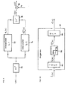
- ak / el converter 1 shows an acoustic-electrical (ak / el) converter 1 with downstream analog / digital (A / D) converter 3, one digital gain filter section 5, which on the output side to a digital / analog (D / A) converter 7, the latter to the electrical-acoustic (el / ak) converter 9 acts.
- the feedback signal y (t) is the Useful signal v (t) superimposed and the input of the ak / el converter 1 supplied, the output side, at the times nT, for the digital processing required time-discrete samples d (nT) returns.
- the stride length ⁇ of the LMS algorithm for the preservation of the speech signal transmission is chosen as small as possible, with which the adaptation of the compensator filter 15 to the interference feedback path 11 accordingly slowly becomes what the possible increase in gain on route 5, limited for reasons of stability.
- time domain / frequency domain transformation is not carried out in front of the differential unit 13 f , as shown in FIG. 2, but rather that the difference is formed in the time domain, can surprisingly be obtained the required time invariance of the system.
- suitably overlapping block division it is possible to implement the time domain / frequency domain transformations that are still used with significantly smaller block lengths, which in turn increases the compensation efficiency and therefore enables the gain on the gain filter section 5 f according to FIG. 2 to be increased drastically.
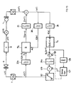
- FIG. 3 is based on a signal flow / functional block diagram a basic principle of the present invention or that of the invention Hearing aid shown. It is in it the reference numerals already used with reference to FIGS. 1 and 2 for the function blocks and signals already described there used.
- the difference signal r (nT) is converted at a LOT transformation unit 20 into the adaptation control signal E [k], which is fed to the adaptation input A f of the compensator filter 15 f . Because the time domain / frequency domain transformation takes place in the LOT transformation unit 20 in blocks of a predetermined number of samples from the difference signal r (nT), [k] denotes the number of the signal block appearing on the output side of the transformation unit 20.
- the difference signal r (nT) is supplied to the amplification filter section 5 in the time domain and fed to the el / ak converter 9 via the D / A converter 7.
- the D / A converter 7 is acted upon by the time-discrete output signal u (nT) of the amplification filter section 5.
- This output signal u (nT) is fed to a further orthogonal transformation unit 22, where it is converted from the time domain to the frequency domain.
- the output signal of the transformation unit 22 is fed as an input signal to the input E f of the compensator filter 15 f .
- the output signal Y and [k + 1] of said filter 15 f is transformed back into the time domain at a reverse transformation unit ILOT 24 and its output signal y and (nT) is fed to the difference forming unit 13 as a discrete-time signal.
- the amplification filter section 5 f is preceded by a transformation unit LOT 28 and the D / A converter 7 is a reverse transformation unit ILOT 26; the transformation unit 22 according to FIG. 3 is omitted.
- FIG. 3 shows, as mentioned, a first form of implementation which corresponds to the definition according to claim 2, namely in which a respective transformation unit LOT 20 or 22 is arranged upstream of the signal input E f and the adaptation input A f of the compensator filter 15 f .
- a preferred embodiment variant is that according to FIG. 4, which corresponds to the definition according to claim 3, according to which the adaptation input A f of the compensating filter 15 f and the input of the amplification filter section 5 f are preceded by a LOT transformation unit 20 or 28 and the input of the D / A converter 7 a corresponding ILOT reverse transformation unit 26.
- the gain filter 5 f is also preceded by a LOT transformation unit 28, the input of the D / A converter 7 is an ILOT reverse transformation unit 26, and further the output of the compensator filter 15 f is followed by an ILOT reverse transformation unit 24.
- These transformation or reverse transformation units 28, 24 and 26 operate in the mentioned preferred embodiment according to the "overlap-save” technique.
- the LOT transformation unit 20 upstream of the adaptation input A f in particular according to FIG. 4, preferably works according to the "overlap-add" principle.
- the time discrete differential signal r (nT) of a single LOT transform unit 30 is fed to here, from whose output signal both the adaption input A f supplied adaptation signal E [k] as well as that of the enhancement filter path 5 f supplied input signal R [k ] is formed.
- the overlapping orthogonal transformations are based preferably at the DFT.
- FIG. 6 shows a form of realization of the data transmission path between the time-discrete difference signal r (nT) on the output side of the difference forming unit 13 for the adaptation signal E [k] or the input signal R [k] to the amplification filter section 5 f according to FIG. 5.
- an overlapping orthogonal transformation unit 30a based on the DFT follows the output of the difference formation unit 13 with the time-discrete difference signal r (nT).
- the actual gain filter 40 follows first, which is followed by a delay unit 42 with corresponding intermediate storage.
- the block signal U [k + 1] available on the output side is now supplied on the one hand to the input E f of the compensator 15 f and on the other hand is subjected to an inverse DFT of the "overlap-save" type in the ILOT unit 26. Since the corresponding time signal u (nT) is delayed by a partial block length N, the numbering of U [k + 1] with the block number k + 1 is justified in retrospect.
- FIG. 8 shows a preferred expansion variant of the compensator filter 15 f on the hearing aid according to the invention according to FIG. 5.
- the block signals U [k + 1] to are thereby buffered with delay units of the type, as shown at 56 U [k + 1-L] provided and, based on this, with the aid of partial compensators, the first of which is referred to in FIG. 8 as unit 50, which generates the partial estimates Y and 1 [k + 1] to Y and L [k + 1], which in turn are provided in unit 52 for Overall estimate Y and [k + 1] can be added.
- the ILOT unit 24 in the preferred variant via an inverse DFT of the "overlap-save" type, then transforms back into the time domain.
- the partial estimate Y and 1 [k + 1] arises at the output of the multiplication unit 64, on which the block signals U [k + 1] and the block weight H and 1 [k + 1] act at the input.
- the block weight H i [k + 1] represents the current estimate in the frequency range for the i-th subrange of length N of the discrete-time impulse response h of the acoustic-mechanical interference feedback 11.
- the estimate H i [k + 1] is preceded by the formation of Y and i, j [k + 1] updated using the old estimate H i [k].
- the block signal acts for this purpose, again with reference to the partial compensator 1 U [k + 1-1] and the step size ⁇ [k + 1-1] to the multiplication unit 54, which on the output side is led to the multiplication unit 58 together with the block signal E [k].
- the output of unit 58 is then in summation unit 60 according to the formula used to update H 1 [k + 1].
- j denotes the block location and i the partial compensator number.
- the index (*) stands for conjugate complex.
- any known method for guiding the Step size ⁇ [k] can be used.
- FIG. 9 shows a preferred variant today for generating the normalized step size ⁇ [k] according to FIG. 8, which is also used to stop the adaptation process.
- this block signal is used before the supply to the multiplication unit 54 to calculate the current block signal ⁇ [k] by feeding the block signal U [k] to a power acquisition unit 70 is, which in turn on two interpolation filters 72, respectively. 74 acts.
- these interpolation filters control the scaling unit 78, which ultimately supplies the scaling variable S [k] required for the normalization of the reference step size ⁇ 0 at the input of the multiplication unit 80.
- the interpolation filters work according to the formula and are parameterized with ⁇ and c.
- the index j denotes the block location.
- the scaling variable S [k] is now used on the one hand via the output of the filter 72, in FIG. 9 as a block signal P U [k], to normalize the reference step size ⁇ 0 , but on the other hand also via the output of the filter 74 in FIG 9 referred to as block signal P U min [k], for freezing the adaptation process of individual frequency components when the power is insufficient.
- the scaling variable S [k] is according to the formula formed, the j denoting the block location as usual.
- FIG. 10 shows a further preferred variant which, with the use of partial compensators according to FIG. 8, significantly improves the speech quality, with otherwise the same parameters.
- the estimate H and i [k + 1] of the partial compensator i previously the multiplication with U [k + 2-i] in unit 64 of FIG. 8, via a projection unit 62.
- the block weight H and i [k + 1] is subjected to an inverse DFT (unit 82), then cleaned by zeroing the block locations with index N to 2N-1 (unit 84) and finally transformed back into the frequency range (unit 86) .
- the electrical-acoustic converter 9 is not linear in the sense that it no longer converts the input signal into the output signal linearly from certain input signal amplitudes.
- the signal path via compensation filter 15 f should be modeled as exactly as possible over the signal path via function blocks 7, 9, 11, 1 and 3 and, according to the previous explanations, the nonlinearities mentioned on converter 9 should not can reproduce.
- the maximum output level should also be adjustable in the hearing aid according to the individual needs of the user. The problem arises that the converter 9 is driven into its non-linear range, of course only if the individually set maximum output level can drive the converter in the mentioned range at all.
- Hearing aid the gain filter 5 one in Time range working, preferably adjustable limiter unit 90 downstream, which is the output signal of the gain filter 5 limited in amplitude so that the Converter 9 is never driven into its non-linear range and which also allows the maximum output sound level at Converter 9, according to individual needs, in particular also set deeper, like this with the double arrows is indicated.
- this is achieved in that the amplification filter 5 f operating in the frequency range is followed by a unit 90 f , which limits the frequency components of the signal spectrum, taking into account their mutual phase position, in the frequency range in such a way that the output of the conversion unit 26 and the Digital / analog converter 7 produces a time-variable signal u (t) which never drives the converter 9 into the non-linear transmission range and which also allows the maximum individual modulation to be set.
- FIG. 11 shows a further embodiment variant of the hearing aid according to the invention, which largely corresponds to that shown in FIG. 4, with the difference that the reverse transformation unit 26 according to FIG. 4, now 26a, is provided directly on the output side of the amplification filter unit 5 f and on the input side of the Compensation filter 15 f a LOT transformation unit 22a of the type already discussed is arranged.
- FIG. 4 which, as explained above, as well as FIG. 5, represents a preferred embodiment variant of the inventive hearing aid, the provision of a limiter unit is only possible in the frequency range because such a unit is also in the signal path with the compensation filter 15 f must be effective.
- this enables here functional block structure shown the provision of a Time domain working limiter unit 90, which is essential is easier to implement than one operating in the frequency domain.
- FIG. 12 shows a preferred embodiment variant of the signal processing on the device according to FIG. 11 upstream of the compensation filter 15 f or downstream of the amplification filter 5 f .
- the non-linearity of the electrical-acoustic transducer 9 is basically simulated, ie modeled, in the signal path with the compensation filter 15 f . This is implemented by a modeling unit 92, upstream of the transformation unit 22a according to FIG. 11 and thus operating in the time domain, and / or by a modeling unit 92 f , downstream of the transformation unit 22a and therefore operating in the frequency domain.
- the modeling unit 92 can, for example, as in R. Isermann, "Identification of dynamic systems", Springer-Verlag, 2: 238, 1988, proposed as a simplified Wiener model will be realized.
- the transformation into the time domain between the gain filter 5 f and the compensator filter 15 f also allows the addition of a nonlinear correction filter in the signal path with the gain filter 5 f in the same manner described above.
- this is implemented by a modeling unit 94, connected downstream of the transformation unit 26a and thus operating in the time domain, and / or by a modeling unit 94 f , connected upstream of the transformation unit 26a and therefore operating in the frequency domain.
- FIG. 13 shows the implementation of a method according to the invention Speaker model shown in the time domain.
- inventive Hearing aid is used, according to Fig. 3 and 11 at the location of block 90 and according to FIG. 12 instead of blocks 92 or 90 and 94.
- ⁇ a pre-filter 100 with the transfer function F 1 ( ⁇ ), essentially with a low-pass characteristic.
- the cutoff frequency ⁇ 1 in the Bode diagram of the filter characteristic, which is shown qualitatively in block 100, is approximately 0.8 kHz, the gain
- the asymptote slope S 1 is approximately 0dB / DK.
- the identification variables namely corner frequency ⁇ 1 and the asymptotic slopes S 1 and S 2 , as well as the amplification, for example at the corner frequency ⁇ 1 , are identified by identifying the loudspeaker or transducer 9 to be modeled.
- a linear amplifier unit 102 is provided downstream of the prefilter 100, and the gain factor K is set to this.
- a non-linear amplification unit 104 is provided downstream of the linear amplification unit 102.
- the gain is nonlinear Gain unit 104 one, with which the gain characteristic has slope one around the origin.
- Input signal deviation x shows the nonlinear gain characteristic, as known from the loudspeaker or converter 9, saturation behavior on.
- the coefficients a, b, c, d and the gain K are again based on the actual speaker to be modeled or converter 9 identified.
- a linear amplification unit 106 Downstream of the non-linear amplification unit 104, a linear amplification unit 106 is again provided, by means of which the amplification K of the linear amplification element 102 is compensated for - K -1 -.
- a filter unit 108 is provided downstream of it, essentially with a high-pass characteristic, which, as can be seen, essentially compensates for the frequency response of the pre-filter 100.
- Signs of saturation or limitation can besides the Two causes already mentioned, namely deliberate limitation the maximum output signal level of the converter 9 according to individual needs or modulation of the converter 9 in its transducer-specific, non-linear saturation range, based on another cause, namely waste the battery voltage, which the device according to the invention feeds.
- the aging of the battery that powers the device causes a decrease in signal amplification in particular at the D / A converter 7 and a reduction in the headline limit, i.e. the maximum analog modulation range decreases with decreasing Battery voltage lower.
- the battery's output impedance usually appears in series with the impedance of the electrical-acoustic converter 9. This changes the towards the end of the battery life Battery output impedance and thus the latter, the substitute image downstream of the D / A converter 7, m.W., change it the one to be modeled, as explained, on the output side of the converter 7 appearing non-linearities.
- the limiter unit 90 in the time domain or 90 f in the frequency domain by means of the instantaneous battery voltage and / or the instantaneous one To control battery impedance with regard to its limiting effect.
- FIG. 14 This procedure is shown schematically in FIG. 14.
- the current battery voltage U B and / or the current impedance is measured on a measuring unit 122 Z. B measured, resulting in corresponding measurement signals e (U B ) or e ( Z. B ).
- These measurement signals control the limiter unit 90, analogously in the frequency range the limiter unit 90 f according to FIGS. 4, 5, 11 or 12, 14 and / or the model units 92, 92 f or 94, 94 f from FIGS. 12, 13, 14.
- the measurement signals e are preferably used after digitization, for which purpose the measurement unit 122 is provided on the output side with an A / D converter (not shown).
- model parameters on the model units 92 and 92 f , 94 and 94 f are modified in the function of the above-mentioned measured variables on the battery 120 or by means of values stored in tables that can be called up and activated by the current measured variables.
- a gain loss on the D / A converter 7 is compensated for due to a decrease in the battery voltage: If the battery voltage decreases and thus the gain on the converter 7, the measurement signal e at block 7 the gain, compensatory, increased accordingly.
- the battery voltage drop acts simultaneously as a signal limitation by a limiter and is best and preferably simulated by a battery output voltage-controlled limiter block 90 b in front of the loudspeaker model 92 or 92 f according to FIG. 14.
- the blocks 90 can be omitted, as may 92 or 92 f blocks 94 and 94 f omitted when provision of the blocks, and there is a relatively low cost a battery voltage-independent, in this realization, stable Feedback suppression achieved according to the invention.
- the function of the mentioned block 90 b can be taken over completely by providing the battery output voltage-controlled block 90 or 90 f according to FIGS. 4 and 5.
- a non-linear model of the acoustic-electrical converter 1 possibly also taking into account the behavior of the A / D converter 3, switched between the output of the compensator filter 15 (FIG. 1) or 15 f (for example FIG. 11) and the subtraction input of the differential unit 13, depending on Arrangement operating in the frequency or time domain, as entered at 91 or 91 f in FIG. 11.
- the explanations apply analogously to those which were made with regard to the model 92, 92 f of the electrical-acoustic transducer.
- a further improvement in the effect of the compensation filter section 15 f can be achieved by superimposing, if necessary, noise r in the time domain, as shown schematically in FIG. 15, on the output side of the gain filter 5 f .
- the instantaneous signal spectrum on the output side of the amplification filter 5 f is examined on a spectrum detector 125, for example on how very individual spectral lines are superior in terms of performance, i.e. how much the spectrum profile is peaked, maW, generally, for example, the energy density distribution of the spectrum .
- a spectrum detector 125 for example on how very individual spectral lines are superior in terms of performance, i.e. how much the spectrum profile is peaked, maW, generally, for example, the energy density distribution of the spectrum .
- a predetermined limit profile such as a predetermined energy distribution from dominant spectral lines to other spectral lines
- digital noise r is preferably coupled into the superimposition unit 129 via a noise generator 127.
- a filter unit as shown at 133 in FIG. 16, can preferably be connected downstream of the noise generator 127, which filter controls the noise in such a way that it is sufficiently weak compared to the instantaneous signal transmitted at the converter 9
- Useful signal for example by 40
- the noise can also be coupled in the frequency domain if necessary will. If the noise is injected in the time domain, for example, the noise generator 127 consists of a BPRN, in the frequency range according to 127a in FIG. 17, for example from a table with noise spectra or a Noise algorithm.
- the noise generator 127 consists of a BPRN, in the frequency range according to 127a in FIG. 17, for example from a table with noise spectra or a Noise algorithm.
- the output signal of the amplification filter 5 f is examined on a spectrum shape detector unit 125a, and when the spectrum shape leaves a predetermined limit characteristic, the output signal of the noise generator 127, which is passed through the linear filter 133, is represented by the signal u ( 15, preferably superimposed on the input side of the limiter unit 90.
- the transmission behavior of the filter 133 is preferably controlled by the current spectrum.
- FIG. 17 shows a preferred embodiment variant of the noise lock in the frequency range according to the dashed embodiment variant with block 131 of FIG. 15.
- the spectrum on the output side of the amplification filter 5 f is examined on a spectrum shape detector unit 125 b , analogously to the unit 125 a of FIG. 16.
- the output signal of a noise generator 127a which, for example, noise spectra stored in tables and are available is, the output side of the amplifying filter 5 f then layered over a shaping filter 137 of the spectrum, as shown schematically by the switch 135a, when the spectrum shape detecting unit 125 b detects a current spectrum shape , which necessitates the noise switching mentioned.
- the noise in the frequency range is superimposed on an addition unit 129a.
- the shaping filter 137 is in turn controlled by the current spectrum, for example on the output side of the gain filter 5 f .
Landscapes
- Acoustics & Sound (AREA)
- Signal Processing (AREA)
- Neurosurgery (AREA)
- Otolaryngology (AREA)
- Physics & Mathematics (AREA)
- Engineering & Computer Science (AREA)
- Health & Medical Sciences (AREA)
- General Health & Medical Sciences (AREA)
- Amplifiers (AREA)
- Stereophonic System (AREA)
- Complex Calculations (AREA)
- Filters That Use Time-Delay Elements (AREA)
- Finger-Pressure Massage (AREA)
- Adornments (AREA)
Claims (34)
- Prothèse auditive avec un convertisseur acoustique/électrique (1), avec un convertisseur A/N (3) placé côté sortie et un convertisseur électrique-acoustique (9) équipé d'un convertisseur N/A (7) côté entrée, avec un chemin de filtre amplificateur (5) placé entre les convertisseur A/N et N/A (3, 7), et un filtre compensateur (15f) adaptatif, dont l'entrée de signal est reliée fonctionnellement à l'entrée de convertisseur N/A, dont la sortie de signal est reliée fonctionnellement à une entrée d'une unité de formation de différence (13), la deuxième entrée de l'unité de formation de différence (13) étant reliée fonctionnellement à la sortie du convertisseur A/N (3), sa sortie agissant sur une entrée d'adaptation (Af) du filtre compensateur (15f) ainsi que sur l'entrée du chemin de filtre amplificateur (5f), en outre les signaux amenés au signal (Ef) et à l'entrée d'adaptation (Af) du filtre compensateur (15f) étant transformés, en au moins une unité de transformation (20, 28) exécutant une transformation orthogonale rapide, la transformation se faisant avec passage d'une plage de temps à une plage de fréquence, caractérisée en ce que la au moins une unité de transformation (22, 20; 20, 28) est disposée côté sortie de l'unité de formation de différence (13) et, entre la sortie du filtre compensateur (15f) ainsi que l'entrée associée de l'unité de formation de différence (13), agissant une unité de retransformation (24) correspondant à l'unité de transformation.
- Prothèse selon la revendication 1, caractérisée en ce qu'une unité de transformation (22, 20) est respectivement mise en circuit en amont de l'entrée de signal (Ef) et de l'entrée d'adaptation (Af) du filtre compensateur (15f).
- Prothèse selon la revendication 1, caractérisée en ce que, en amont de l'entrée d'adaptation (Af) du filtre compensateur (15f) ainsi que de l'entrée du filtre d'amplification (5f), est respectivement mise en circuit une unité de transformation (20, 28), et une unité de retransformation (26) est mise en amont du convertisseur N/A (7).
- Prothèse selon la revendication 1, caractérisée en ce qu'une unité de transformation 30 commune est mise en circuit conjointement en amont de l'entrée d'adaptation (Af) du filtre compensateur (15f) ainsi que de l'entrée du chemin de filtre à amplification (5f).
- Prothèse selon l'une des revendications 1 à 4, caractérisée en ce qu'une unité de transformation (20, 28; 30; 30a, 32, 34), mise en amont de l'entrée du filtre amplificateur (5f), une unité de retransformation, mise en aval de la sortie du filtre compensateur (15f) et une unité de retransformation, mise en amont (26) du convertisseur N/A, travaillent selon la technique "overlap-save".
- Prothèse selon l'une des revendications 1 à 5, caractérisée en ce qu'une unité de transformation (30; 30a) mise en amont de l'entrée d'adaptation (Af) du filtre compensateur (15f) travaille selon la technique "overlap-add".
- Prothèse selon l'une des revendications 1 à 6, caractérisée en ce qu'en aval de la sortie de l'unité de formation de différence (13) est mis en circuit une unité de transformation (30a) qui travaille selon la technique "overlap-add", sa sortie agissant sur l'entrée d'adaptation (Af) du filtre compensateur (15f) et est amenée à un dispositif à mémoire à blocs (32), dans lequel des blocs de signaux successifs se suivant, constitués selon la technique "overlap-add" sont mémorisés, des emplacements mémoire associés, prévus pour des emplacements de blocs associés, étant additionnés avec le bon signe sur une unité d'addition (34), de manière que le bloc de sortie de l'unité d'addition constitue un bloc suivant la technique "overlap-save" et que la sortie de l'unité d'addition (34) soit amenée à l'entrée du chemin de filtre amplificateur (5f).
- Prothèse selon l'une des revendications 1 à 7, caractérisée en ce que le chemin de filtre amplificateur (5f) comprend un filtre amplificateur (40), ainsi que, mise en circuit en aval de celui-ci, une unité de retardement (42).
- Prothèse selon l'une des revendications 7 ou 8, caractérisée en ce que le filtre compensateur (15f) comprend :des étages de retardement (56) mis en circuit, en série, en aval de l'entrée (Ef) du filtre compensateur,un nombre 1 ≤ i ≤ L de compensateurs partiels (50) auxquels sont générés des signaux d'estimation partielsune unité d'addition (52) sur laquelle sont additionnés les signaux d'estimation partiels y andi[k+1] de tous les 1 ≤ i ≤ L compensateurs partiels (50) et dont la sortie constitue la sortie du filtre compensateur (15f).
- Prothèse selon la revendication 9, caractérisé en ce que chaque compensateur partiel (50) comprend :une entrée de compensateur partiel reliée à l'entrée (Ef) du filtre compensateur (15f), par l'intermédiaire d'un nombre donné d'étages de retardement (56), le nombre d'étages de retardement correspondant au nombre de compensateurs partiels mis en circuit en amont d'un compensateur partiel, chaque étage de retardement (56) reliant l'entrée et la sortie d'un compensateur partiel (50),un premier étage de multiplication (54) relié fonctionnellement à la sortie du compensateur partiel;mise en circuit en aval de la sortie du premier étage d'une multiplication (54), une entrée d'un deuxième étage de multiplication (58), dont la deuxième entrée est reliée fonctionnellement à l'entrée d'adaptation (Af),la sortie du deuxième étage de multiplication (58) agissant, par l'intermédiaire d'une unité d'accumulation (60), sur une entrée d'un troisième étage de multiplication (64), dont la deuxième entrée est reliée fonctionnellement à l'entrée du compensateur partiel (50) et dont la sortie agit sur l'unité d'addition (52).
- Prothèse selon l'une des revendications 1 à 10, caractérisée en ce que, en amont de l'entrée de l'unité de filtre amplificateur, est mise en circuit une unité de transformation,, dont le signal de sortie agit, outre sur le chemin de filtre amplificateur, sur l'unité de détection de puissance (70) dont le signal de sortie alors, lorsque l'énergie du signal à la sortie de l'unité de transformation dépasse une valeur seuil donnée, commande l'efficacité d'un signal sur l'entrée d'adaptation.
- Prothèse selon la revendication 11, caractérisée en ce que, sur la deuxième entrée du premier étage de multiplication (54), agit la sortie d'une quatrième unité de multiplication (80), à une entrée de laquelle est amené un signal correspondant à une valeur de pas de référence (µ0), à la deuxième entrée duquel est amené la sortie d'une unité de mise à l'échelle (70), à cette dernière étant amenées les sorties de deux filtres à interpolation (72, 74), les deux étant alimentés par l'unité de détection de puissance (70) depuis le signal de sortie du chemin de filtre amplificateur.
- Appareil selon la revendication 12, caractérisé en ce qu'au lieu d'un signal des filtres d'interpolation (74) est amené un signal, temporellement constant, de l'unité de mise à l'échelle (78) (γ = 1).
- Prothèse selon l'une des revendications 12 ou 13, caractérisée en ce que, à la sortie de l'unité d'accumulation (60) et à l'entrée du troisième étage de multiplication (64), sont branchés de façon intermédiaire une unité de retransformation (82), une unité de mise à zéro (84) ainsi qu'une unité de transformation (86).
- Prothèse selon l'une des revendications 1 à 14, caractérisée en ce qu'une unité à limitation d'amplitude (90, 90f) est mise en circuit en amont du convertisseur électrique acoustique (el/ac) (9).
- Prothèse selon l'une des revendications 3 à 14, caractérisée en ce que, en amont de l'entrée du filtre de compensation (15f), est mise en circuit une unité de transformation (22a) et, en aval de la sortie du chemin de filtre amplificateur (5f), est mise en circuit une unité de retransformation (26a) ainsi qu'une unité de limitation d'amplitude (90).
- Prothèse selon l'une des revendications 1 à 16, caractérisée en ce qu'en amont et/ou en aval du filtre compensateur (15f) est mise en circuit au moins une unité moduleuse (91, 91f, 92, 92f) travaillant dans la plage des fréquences et/ou des temps, modulant le convertisseur électro-acoustique (9) et/ou le convertisseur acoustique-électrique (1).
- Prothèse selon l'une des revendications 3 ou 4, caractérisée en ce que, en amont du filtre de compensation (15f), est mise en circuit une unité de transformation (22a) et, en aval du chemin de filtre amplificateur (5f), est mise en circuit une unité de retransformation (26a) et, en amont de l'unité de transformation (22a), mis en circuit en amont du filtre de compensation (15f), est mis en circuit une unité modélisante (92) dans la plage des temps, en amont du convertisseur électrique-acoustique (9) et/ou du convertisseur acoustique-électrique (1), et/ou en aval de l'unité de transformation (22a) est mise en circuit une unité modélisante dans la plaque des fréquences (92f), en aval du convertisseur électrique acoustique (9) et/ou du convertisseur acoustique/électrique (1).
- Prothèse selon l'une des revendications 1 à 18, caractérisée en ce que, en amont du filtre à compensation (15f), en aval du filtre amplificateur (5f), sont respectivement prévues une unité modélisante (92; 94), de préférence modélisante dans la plage des fréquences, agissant sur le convertisseur électrique-acoustique (9) et/ou sur le convertisseur acoustique-électrique (1).
- Prothèse selon l'une des revendications 1 à 19, caractérisé en ce qu'il comprend au moins une unité limiteuse (90, 90f, 90b), travaillant dans la plage des temps ou dans la plage des fréquences et alimentée électriquement par une batterie, en ce qu'en outre est prévu un dispositif de mesure, destiné à appréhender l'état REEL de batterie (122) dont la sortie commande l'unité limiteuse.
- Prothèse selon l'une des revendications 1 à 20, caractérisée en ce que le convertisseur N/A présente uné entrée de commande d'amplification, la prothèse étant alimentée par batterie, un dispositif de mesure (122) pour l'état REEL de la batterie d'alimentation (120) étant prévu, dispositif dont la sortie est amenée à l'entrée d'amplification du convertisseur N/A.
- Prothèse selon l'une des revendications 1 à 21, caractérisée en ce qu'elle comprend au moins une unité modélisante (91, 91f, 92, 92f, 94, 94f), modélisant de préférence dans la plage des temps, en agissant sur le convertisseur électrique-acoustique (9) et/ou sur le convertisseur acoustique-électrique (1), l'alimentation se faisant par batterie et comprend un dispositif de mesure (122) destiné à l'état REEL de la batterie (120), dont la sortie est menée à des entrées de commande de paramètres prévues sur la au moins une unité modélisante.
- Prothèse selon l'une des revendications 1 à 22, caractérisée en ce que de préférence dans la plage des temps, est amené (129, 135a) au filtre de compensation (15f), côté entrée, de préférence au moins par moments, un signal de bruit (r).
- Appareil selon la revendication 23, caractérisé en ce que le signal est amené côté sortie du filtre amplificateur à une unité de détection (125, 125a, 125b) sur lequel la forme instantanée de son spectre est ensuite examinée, pour savoir si une condition prédéterminée est satisfaite ou non, et en ce que le signal de sortie de l'unité de détection commande l'immixtion (135, 135a) du signal de bruit.
- Prothèse selon la revendication 23, caractérisée en ce que le signal de bruit est amené par l'intermédiaire d'un filtre de formage qui est commandé par le spectre momentané du signal de sortie de l'unité de différence.
- Prothèse selon l'une des revendications 1 à 22, caractérisée en ce qu'un générateur de bruit (127a) est prévu dans la plage des fréquences, générateur dont le signal de sortie est couplé, avec superposition, au côté sortie du chemin de filtre amplificateur (5f).
- Prothèse selon la revendication 26, caractérisée en ce que la sortie du générateur de bruit (127a) est amenée, par un filtre de formage (137), auquel est amené à titre de signal de commande pour son comportement en formage, le spectre momentané d'un signal, du côté sortie de l'unité de formation de différence (13).
- Prothèse selon l'une des revendications 1 à 27, caractérisée en ce que, au moins par moments, est superposé au signal électriquement transmis à cet endroit, un signal de bruit, ceci étant fait par l'intermédiaire d'un filtre linéaire (133) dont le comportement en transmission est commandé par le spectre momentané du signal transmis électriquement.
- Prothèse selon l'une des revendications 1 à 28, caractérisé en ce que dans une ramification de compensation est prévue une unité modélisante (91, 91f), agissant sur le comportement en transmission du convertisseur acoustique-électrique (1) de la prothèse.
- Prothèse selon l'une des revendications 1 à 29, caractérisée en ce qu'une unité de transmission électrique, restituant le comportement en transmission du convertisseur électrique-acoustique est prévue, comprenant une partie de transmission linéaire (100, 102, 108) ainsi qu'une partie de transmission non-linéaire (104).
- Prothèse selon la revendication 30, caractérisée en ce que la partie de transmission linéaire comprend des amplificateurs linéaires ainsi que des filtres.
- Prothèse selon la revendication 31, caractérisée en ce que la partie de transmission linéaire comprend un pré-filtre placé côté entrée, doté sensiblement d'une caractéristique passe-bas, en aval duquel est mise en circuit la partie de transmission non-linéaire (104), en aval de cette dernière étant mise en circuit une unité de filtre de compensation (108), avec une réponse en fréquence sensiblement inverse de la réponse en fréquence du préfiltre.
- Prothèse selon la revendication 32, caractérisée en ce que, en amont de l'unité de transmission non-linéaire (104), est mis en circuit un composant d'amplification linéaire (102) et, en aval de l'unité de transmission non-linéaire, est mis en circuit un composant de compensation amplificateur linéaire (106), assurant une compensation de l'amplification du composant amplificateur linéaire.
- Prothèse selon la revendication 31, caractérisée en ce que la partie non-linéaire présente une caractéristique de transmission ayant un comportement de saturation.
Priority Applications (1)
| Application Number | Priority Date | Filing Date | Title |
|---|---|---|---|
| EP94117510A EP0656737B1 (fr) | 1993-11-10 | 1994-11-07 | Prothèse auditive avec suppression du couplage acoustique |
Applications Claiming Priority (3)
| Application Number | Priority Date | Filing Date | Title |
|---|---|---|---|
| EP19930118186 EP0585976A3 (en) | 1993-11-10 | 1993-11-10 | Hearing aid with cancellation of acoustic feedback |
| EP93118186 | 1993-11-10 | ||
| EP94117510A EP0656737B1 (fr) | 1993-11-10 | 1994-11-07 | Prothèse auditive avec suppression du couplage acoustique |
Publications (2)
| Publication Number | Publication Date |
|---|---|
| EP0656737A1 EP0656737A1 (fr) | 1995-06-07 |
| EP0656737B1 true EP0656737B1 (fr) | 1998-01-21 |
Family
ID=8213409
Family Applications (2)
| Application Number | Title | Priority Date | Filing Date |
|---|---|---|---|
| EP19930118186 Withdrawn EP0585976A3 (en) | 1993-11-10 | 1993-11-10 | Hearing aid with cancellation of acoustic feedback |
| EP94117510A Expired - Lifetime EP0656737B1 (fr) | 1993-11-10 | 1994-11-07 | Prothèse auditive avec suppression du couplage acoustique |
Family Applications Before (1)
| Application Number | Title | Priority Date | Filing Date |
|---|---|---|---|
| EP19930118186 Withdrawn EP0585976A3 (en) | 1993-11-10 | 1993-11-10 | Hearing aid with cancellation of acoustic feedback |
Country Status (5)
| Country | Link |
|---|---|
| US (1) | US5661814A (fr) |
| EP (2) | EP0585976A3 (fr) |
| AT (1) | ATE162679T1 (fr) |
| DE (1) | DE59405093D1 (fr) |
| DK (1) | DK0656737T3 (fr) |
Cited By (1)
| Publication number | Priority date | Publication date | Assignee | Title |
|---|---|---|---|---|
| DE19957128C1 (de) * | 1999-11-26 | 2001-08-16 | Siemens Audiologische Technik | Verfahren zur Pegelbegrenzung in einem digitalen Hörhilfegerät sowie digitales Hörhilfegerät |
Families Citing this family (32)
| Publication number | Priority date | Publication date | Assignee | Title |
|---|---|---|---|---|
| KR100378449B1 (ko) * | 1994-04-12 | 2003-06-11 | 코닌클리케 필립스 일렉트로닉스 엔.브이. | 개선된에코제거기를갖는신호증폭기시스템 |
| KR100573500B1 (ko) * | 1996-02-27 | 2006-09-20 | 코닌클리케 필립스 일렉트로닉스 엔.브이. | 신호코딩및디코딩방법및장치 |
| US5909497A (en) * | 1996-10-10 | 1999-06-01 | Alexandrescu; Eugene | Programmable hearing aid instrument and programming method thereof |
| DE59814316D1 (de) | 1998-01-14 | 2008-12-18 | Bernafon Ag | Schaltung und Verfahren zur adaptiven Unterdrückung einer akustischen Rückkopplung |
| JP3267556B2 (ja) * | 1998-02-18 | 2002-03-18 | 沖電気工業株式会社 | エコー除去装置および送話器 |
| US6347148B1 (en) | 1998-04-16 | 2002-02-12 | Dspfactory Ltd. | Method and apparatus for feedback reduction in acoustic systems, particularly in hearing aids |
| KR100363252B1 (ko) * | 1999-04-30 | 2002-11-30 | 삼성전자 주식회사 | 다중대역 보청기를 위한 적응 피드백 제거장치 및 방법 |
| DE19922133C2 (de) * | 1999-05-12 | 2001-09-13 | Siemens Audiologische Technik | Hörhilfsgerät mit Oszillationsdetektor sowie Verfahren zur Feststellung von Oszillationen in einem Hörhilfsgerät |
| ATE339865T1 (de) * | 1999-07-19 | 2006-10-15 | Oticon As | Rückkopplungsunterdrückung unter verwendung von bandbreite-detektion |
| US6937738B2 (en) * | 2001-04-12 | 2005-08-30 | Gennum Corporation | Digital hearing aid system |
| US6633202B2 (en) | 2001-04-12 | 2003-10-14 | Gennum Corporation | Precision low jitter oscillator circuit |
| US7076073B2 (en) | 2001-04-18 | 2006-07-11 | Gennum Corporation | Digital quasi-RMS detector |
| ATE318062T1 (de) * | 2001-04-18 | 2006-03-15 | Gennum Corp | Mehrkanal hörgerät mit übertragungsmöglichkeiten zwischen den kanälen |
| US20020191800A1 (en) * | 2001-04-19 | 2002-12-19 | Armstrong Stephen W. | In-situ transducer modeling in a digital hearing instrument |
| ATE526792T1 (de) * | 2001-08-15 | 2011-10-15 | Sound Design Technologies Ltd | Rekonfigurierbare hörhilfevorrichtung mit niedrigem leistungsverbrauch |
| AU2001291588A1 (en) * | 2001-10-05 | 2001-12-17 | Phonak Ag | Method for verifying the availability of a signal component and device for carrying out said method |
| US6650124B2 (en) | 2001-10-05 | 2003-11-18 | Phonak Ag | Method for checking an occurrence of a signal component and device to perform the method |
| DE10244184B3 (de) * | 2002-09-23 | 2004-04-15 | Siemens Audiologische Technik Gmbh | Feedbackkompensation für Hörgeräte mit Systemabstandsschätzung |
| FR2853804A1 (fr) * | 2003-07-11 | 2004-10-15 | France Telecom | Procede de decodage d'un signal permettant de reconstituer une scene sonore et dispositif de decodage correspondant |
| US7756276B2 (en) | 2003-08-20 | 2010-07-13 | Phonak Ag | Audio amplification apparatus |
| AU2004201374B2 (en) | 2004-04-01 | 2010-12-23 | Phonak Ag | Audio amplification apparatus |
| AU2003236382B2 (en) | 2003-08-20 | 2011-02-24 | Phonak Ag | Feedback suppression in sound signal processing using frequency transposition |
| CN1918942A (zh) * | 2004-02-11 | 2007-02-21 | 皇家飞利浦电子股份有限公司 | 声反馈抑制 |
| US7324651B2 (en) | 2004-03-15 | 2008-01-29 | Phonak Ag | Feedback suppression |
| DK1469702T3 (en) * | 2004-03-15 | 2017-02-13 | Sonova Ag | Feedback suppression |
| US8553899B2 (en) | 2006-03-13 | 2013-10-08 | Starkey Laboratories, Inc. | Output phase modulation entrainment containment for digital filters |
| US8509465B2 (en) | 2006-10-23 | 2013-08-13 | Starkey Laboratories, Inc. | Entrainment avoidance with a transform domain algorithm |
| WO2008051570A1 (fr) | 2006-10-23 | 2008-05-02 | Starkey Laboratories, Inc. | Évitement d'entrainement a filtre auto-régressif |
| US8452034B2 (en) | 2006-10-23 | 2013-05-28 | Starkey Laboratories, Inc. | Entrainment avoidance with a gradient adaptive lattice filter |
| US9654885B2 (en) | 2010-04-13 | 2017-05-16 | Starkey Laboratories, Inc. | Methods and apparatus for allocating feedback cancellation resources for hearing assistance devices |
| US9113276B2 (en) | 2012-03-27 | 2015-08-18 | Starkey Laboratories, Inc. | Automatic reconfiguration of a hearing assistance device based on battery characteristics |
| CA2897054A1 (fr) | 2013-01-11 | 2014-07-17 | Zpower, Llc | Procedes et systemes de recharge d'une batterie |
Family Cites Families (9)
| Publication number | Priority date | Publication date | Assignee | Title |
|---|---|---|---|---|
| US4631749A (en) * | 1984-06-22 | 1986-12-23 | Heath Company | ROM compensated microphone |
| US4658426A (en) * | 1985-10-10 | 1987-04-14 | Harold Antin | Adaptive noise suppressor |
| AU596633B2 (en) * | 1986-01-21 | 1990-05-10 | Antin, Mark | Digital hearing enhancement apparatus |
| US4823795A (en) * | 1987-03-13 | 1989-04-25 | Minnesota Mining And Manufacturing Company | Signal processor for and an auditory prosthesis having spectral to temporal transformation |
| US4815139A (en) * | 1988-03-16 | 1989-03-21 | Nelson Industries, Inc. | Active acoustic attenuation system for higher order mode non-uniform sound field in a duct |
| DE4111884A1 (de) * | 1991-04-09 | 1992-10-15 | Klippel Wolfgang | Schaltungsanordnung zur korrektur des linearen und nichtlinearen uebertragungsverhaltens elektroakustischer wandler |
| DK170600B1 (da) * | 1992-03-31 | 1995-11-06 | Gn Danavox As | Høreapparat med kompensation for akustisk tilbagekobling |
| US5347586A (en) * | 1992-04-28 | 1994-09-13 | Westinghouse Electric Corporation | Adaptive system for controlling noise generated by or emanating from a primary noise source |
| US5444786A (en) * | 1993-02-09 | 1995-08-22 | Snap Laboratories L.L.C. | Snoring suppression system |
-
1993
- 1993-11-10 EP EP19930118186 patent/EP0585976A3/de not_active Withdrawn
-
1994
- 1994-11-07 DE DE59405093T patent/DE59405093D1/de not_active Expired - Lifetime
- 1994-11-07 AT AT94117510T patent/ATE162679T1/de not_active IP Right Cessation
- 1994-11-07 EP EP94117510A patent/EP0656737B1/fr not_active Expired - Lifetime
- 1994-11-07 DK DK94117510T patent/DK0656737T3/da active
- 1994-11-07 US US08/335,180 patent/US5661814A/en not_active Expired - Lifetime
Cited By (1)
| Publication number | Priority date | Publication date | Assignee | Title |
|---|---|---|---|---|
| DE19957128C1 (de) * | 1999-11-26 | 2001-08-16 | Siemens Audiologische Technik | Verfahren zur Pegelbegrenzung in einem digitalen Hörhilfegerät sowie digitales Hörhilfegerät |
Also Published As
| Publication number | Publication date |
|---|---|
| EP0656737A1 (fr) | 1995-06-07 |
| EP0585976A3 (en) | 1994-06-01 |
| DE59405093D1 (de) | 1998-02-26 |
| EP0585976A2 (fr) | 1994-03-09 |
| ATE162679T1 (de) | 1998-02-15 |
| DK0656737T3 (da) | 1998-09-14 |
| US5661814A (en) | 1997-08-26 |
Similar Documents
| Publication | Publication Date | Title |
|---|---|---|
| EP0656737B1 (fr) | Prothèse auditive avec suppression du couplage acoustique | |
| DE3908881C2 (de) | Aktives Geräuschdämpfungssystem mit Digitalfiltern | |
| DE69330642T2 (de) | Hörgerät mit ausgleich der akustischen rückkopplung | |
| DE60028779T2 (de) | Rückkopplungsanullierung mit niederfrequenzeingang | |
| DE2345544C3 (de) | Schallwiedergabesystem | |
| DE69033177T2 (de) | Hörgerät mit Kompensation der akustischen Rückkopplung | |
| EP0930801B1 (fr) | Circuit et procédé pour la suppression adaptative de la réaction acoustique | |
| DE69902687T2 (de) | Hörhilfegerätsystem und hörhilfegerät zur in situ-anpassung | |
| DE2718491C2 (de) | Schaltungsanordnung zur Verstärkung der Signale eines elektromagnetischen Wandlers und zur Vorspannungserzeugung für den Wandler | |
| DE102019123971B4 (de) | Aktives lärmkompensationssystem und verfahren | |
| WO2000031875A1 (fr) | Procede et dispositif de compensation de retards de phase | |
| DE2618268B2 (de) | Verfahren zur Kompression eines Signals und zur Expansion des komprimierten Signals sowie Anordnung zur Durchführung des Verfahrens | |
| DE69327951T2 (de) | Hörgerät mit ausgleich der akustischen rückkopplung | |
| EP1542500B1 (fr) | Prothèse acoustique avec suppression de bruit et procédé correspondant pour la suppression du bruit | |
| EP1872360A1 (fr) | Procede de reproduction d'un parcours secondaire dans un systeme de reduction du bruit actif | |
| EP1406469B1 (fr) | Compensateur de la rétroaction dans les systèmes d'amplification acoustique, prothèse auditive, procédé pour la compensation de la rétroaction et utilisation de ce procédé dans les prothèses auditives | |
| EP1458216B1 (fr) | Appareil et procédé à l'adaption de microphones dans une prothèse auditive | |
| DE69305738T2 (de) | Impedanznachbildung für eine teilnehmerleitungsschnittstellenschaltung | |
| EP2856642B1 (fr) | Amplificateur commuté destiné à une tension d'alimentation variable | |
| EP0542710A1 (fr) | Procédé de traitement de signaux | |
| DE10054540B4 (de) | Verstärkerschaltung, insbesondere Leitungstreiber und Verfahren zur Verstärkung eines Signals, insbesondere Verfahren zum Treiben eines Leitungssignals | |
| DE102006023735A1 (de) | Messbox für eine Hörvorrichtung und entsprechendes Messverfahren | |
| DE2316939C3 (de) | Elektrische Hörhilfeschaltung | |
| EP1020068B1 (fr) | Procede de compensation d'echo, dispositif de compensation d'echo et appareil de telecommunication | |
| DE102009055889A1 (de) | Signalverarbeitungsschaltung zur Erzeugung eines Lautsprechersignals und Signalverarbeitungsverfahren |
Legal Events
| Date | Code | Title | Description |
|---|---|---|---|
| PUAI | Public reference made under article 153(3) epc to a published international application that has entered the european phase |
Free format text: ORIGINAL CODE: 0009012 |
|
| 17P | Request for examination filed |
Effective date: 19950314 |
|
| AK | Designated contracting states |
Kind code of ref document: A1 Designated state(s): AT CH DE DK ES FR GB GR IT LI NL SE |
|
| 17Q | First examination report despatched |
Effective date: 19960704 |
|
| GRAG | Despatch of communication of intention to grant |
Free format text: ORIGINAL CODE: EPIDOS AGRA |
|
| GRAG | Despatch of communication of intention to grant |
Free format text: ORIGINAL CODE: EPIDOS AGRA |
|
| GRAH | Despatch of communication of intention to grant a patent |
Free format text: ORIGINAL CODE: EPIDOS IGRA |
|
| GRAH | Despatch of communication of intention to grant a patent |
Free format text: ORIGINAL CODE: EPIDOS IGRA |
|
| GRAA | (expected) grant |
Free format text: ORIGINAL CODE: 0009210 |
|
| AK | Designated contracting states |
Kind code of ref document: B1 Designated state(s): AT CH DE DK ES FR GB GR IT LI NL SE |
|
| PG25 | Lapsed in a contracting state [announced via postgrant information from national office to epo] |
Ref country code: IT Free format text: LAPSE BECAUSE OF FAILURE TO SUBMIT A TRANSLATION OF THE DESCRIPTION OR TO PAY THE FEE WITHIN THE PRE;WARNING: LAPSES OF ITALIAN PATENTS WITH EFFECTIVE DATE BEFORE 2007 MAY HAVE OCCURRED AT ANY TIME BEFORE 2007. THE CORRECT EFFECTIVE DATE MAY BE DIFFERENT FROM THE ONE RECORDED.SCRIBED TIME-LIMIT Effective date: 19980121 Ref country code: GR Free format text: LAPSE BECAUSE OF NON-PAYMENT OF DUE FEES Effective date: 19980121 Ref country code: ES Free format text: THE PATENT HAS BEEN ANNULLED BY A DECISION OF A NATIONAL AUTHORITY Effective date: 19980121 |
|
| REF | Corresponds to: |
Ref document number: 162679 Country of ref document: AT Date of ref document: 19980215 Kind code of ref document: T |
|
| REG | Reference to a national code |
Ref country code: CH Ref legal event code: NV Representative=s name: TROESCH SCHEIDEGGER WERNER AG Ref country code: CH Ref legal event code: EP |
|
| GBT | Gb: translation of ep patent filed (gb section 77(6)(a)/1977) |
Effective date: 19980126 |
|
| REF | Corresponds to: |
Ref document number: 59405093 Country of ref document: DE Date of ref document: 19980226 |
|
| PG25 | Lapsed in a contracting state [announced via postgrant information from national office to epo] |
Ref country code: SE Free format text: LAPSE BECAUSE OF FAILURE TO SUBMIT A TRANSLATION OF THE DESCRIPTION OR TO PAY THE FEE WITHIN THE PRESCRIBED TIME-LIMIT Effective date: 19980421 |
|
| ET | Fr: translation filed | ||
| REG | Reference to a national code |
Ref country code: DK Ref legal event code: T3 |
|
| PLBQ | Unpublished change to opponent data |
Free format text: ORIGINAL CODE: EPIDOS OPPO |
|
| PLBI | Opposition filed |
Free format text: ORIGINAL CODE: 0009260 |
|
| PLBF | Reply of patent proprietor to notice(s) of opposition |
Free format text: ORIGINAL CODE: EPIDOS OBSO |
|
| 26 | Opposition filed |
Opponent name: SIEMENS AUDIOLOGISCHE TECHNIK GMBH Effective date: 19981019 |
|
| NLR1 | Nl: opposition has been filed with the epo |
Opponent name: SIEMENS AUDIOLOGISCHE TECHNIK GMBH |
|
| PLBF | Reply of patent proprietor to notice(s) of opposition |
Free format text: ORIGINAL CODE: EPIDOS OBSO |
|
| PLBF | Reply of patent proprietor to notice(s) of opposition |
Free format text: ORIGINAL CODE: EPIDOS OBSO |
|
| PLBQ | Unpublished change to opponent data |
Free format text: ORIGINAL CODE: EPIDOS OPPO |
|
| PLAB | Opposition data, opponent's data or that of the opponent's representative modified |
Free format text: ORIGINAL CODE: 0009299OPPO |
|
| PGFP | Annual fee paid to national office [announced via postgrant information from national office to epo] |
Ref country code: AT Payment date: 20001130 Year of fee payment: 7 Ref country code: NL Payment date: 20001130 Year of fee payment: 7 |
|
| R26 | Opposition filed (corrected) |
Opponent name: SIEMENS AUDIOLOGISCHE TECHNIK GMBH Effective date: 19981019 |
|
| NLR1 | Nl: opposition has been filed with the epo |
Opponent name: SIEMENS AUDIOLOGISCHE TECHNIK GMBH |
|
| PG25 | Lapsed in a contracting state [announced via postgrant information from national office to epo] |
Ref country code: AT Free format text: LAPSE BECAUSE OF NON-PAYMENT OF DUE FEES Effective date: 20011107 |
|
| REG | Reference to a national code |
Ref country code: GB Ref legal event code: IF02 |
|
| PLBQ | Unpublished change to opponent data |
Free format text: ORIGINAL CODE: EPIDOS OPPO |
|
| PLAB | Opposition data, opponent's data or that of the opponent's representative modified |
Free format text: ORIGINAL CODE: 0009299OPPO |
|
| R26 | Opposition filed (corrected) |
Opponent name: SIEMENS AUDIOLOGISCHE TECHNIK GMBH Effective date: 19981019 |
|
| PG25 | Lapsed in a contracting state [announced via postgrant information from national office to epo] |
Ref country code: NL Free format text: LAPSE BECAUSE OF NON-PAYMENT OF DUE FEES Effective date: 20020601 |
|
| NLR1 | Nl: opposition has been filed with the epo |
Opponent name: SIEMENS AUDIOLOGISCHE TECHNIK GMBH |
|
| NLV4 | Nl: lapsed or anulled due to non-payment of the annual fee |
Effective date: 20020601 |
|
| PLBP | Opposition withdrawn |
Free format text: ORIGINAL CODE: 0009264 |
|
| PLBD | Termination of opposition procedure: decision despatched |
Free format text: ORIGINAL CODE: EPIDOSNOPC1 |
|
| PLBD | Termination of opposition procedure: decision despatched |
Free format text: ORIGINAL CODE: EPIDOSNOPC1 |
|
| PLBM | Termination of opposition procedure: date of legal effect published |
Free format text: ORIGINAL CODE: 0009276 |
|
| STAA | Information on the status of an ep patent application or granted ep patent |
Free format text: STATUS: OPPOSITION PROCEDURE CLOSED |
|
| 27C | Opposition proceedings terminated |
Effective date: 20041003 |
|
| PGFP | Annual fee paid to national office [announced via postgrant information from national office to epo] |
Ref country code: FR Payment date: 20061108 Year of fee payment: 13 |
|
| PLAB | Opposition data, opponent's data or that of the opponent's representative modified |
Free format text: ORIGINAL CODE: 0009299OPPO |
|
| REG | Reference to a national code |
Ref country code: FR Ref legal event code: ST Effective date: 20080930 |
|
| PG25 | Lapsed in a contracting state [announced via postgrant information from national office to epo] |
Ref country code: FR Free format text: LAPSE BECAUSE OF NON-PAYMENT OF DUE FEES Effective date: 20071130 |
|
| PGFP | Annual fee paid to national office [announced via postgrant information from national office to epo] |
Ref country code: DK Payment date: 20101110 Year of fee payment: 17 |
|
| PGFP | Annual fee paid to national office [announced via postgrant information from national office to epo] |
Ref country code: DE Payment date: 20101104 Year of fee payment: 17 Ref country code: CH Payment date: 20101112 Year of fee payment: 17 |
|
| PGFP | Annual fee paid to national office [announced via postgrant information from national office to epo] |
Ref country code: GB Payment date: 20101103 Year of fee payment: 17 |
|
| REG | Reference to a national code |
Ref country code: CH Ref legal event code: PL |
|
| REG | Reference to a national code |
Ref country code: DK Ref legal event code: EBP |
|
| GBPC | Gb: european patent ceased through non-payment of renewal fee |
Effective date: 20111107 |
|
| PG25 | Lapsed in a contracting state [announced via postgrant information from national office to epo] |
Ref country code: LI Free format text: LAPSE BECAUSE OF NON-PAYMENT OF DUE FEES Effective date: 20111130 Ref country code: CH Free format text: LAPSE BECAUSE OF NON-PAYMENT OF DUE FEES Effective date: 20111130 |
|
| REG | Reference to a national code |
Ref country code: DE Ref legal event code: R119 Ref document number: 59405093 Country of ref document: DE Effective date: 20120601 |
|
| PG25 | Lapsed in a contracting state [announced via postgrant information from national office to epo] |
Ref country code: DK Free format text: LAPSE BECAUSE OF NON-PAYMENT OF DUE FEES Effective date: 20111130 Ref country code: GB Free format text: LAPSE BECAUSE OF NON-PAYMENT OF DUE FEES Effective date: 20111107 |
|
| PG25 | Lapsed in a contracting state [announced via postgrant information from national office to epo] |
Ref country code: DE Free format text: LAPSE BECAUSE OF NON-PAYMENT OF DUE FEES Effective date: 20120601 |