EP0656959B1 - Appareil d'electrolyse pour la production d'hydrogene - Google Patents
Appareil d'electrolyse pour la production d'hydrogene Download PDFInfo
- Publication number
- EP0656959B1 EP0656959B1 EP93919347A EP93919347A EP0656959B1 EP 0656959 B1 EP0656959 B1 EP 0656959B1 EP 93919347 A EP93919347 A EP 93919347A EP 93919347 A EP93919347 A EP 93919347A EP 0656959 B1 EP0656959 B1 EP 0656959B1
- Authority
- EP
- European Patent Office
- Prior art keywords
- hydrogen
- liquid
- oxygen
- electrolytic cell
- pressure
- Prior art date
- Legal status (The legal status is an assumption and is not a legal conclusion. Google has not performed a legal analysis and makes no representation as to the accuracy of the status listed.)
- Expired - Lifetime
Links
Images
Classifications
-
- C—CHEMISTRY; METALLURGY
- C25—ELECTROLYTIC OR ELECTROPHORETIC PROCESSES; APPARATUS THEREFOR
- C25B—ELECTROLYTIC OR ELECTROPHORETIC PROCESSES FOR THE PRODUCTION OF COMPOUNDS OR NON-METALS; APPARATUS THEREFOR
- C25B15/00—Operating or servicing cells
-
- C—CHEMISTRY; METALLURGY
- C25—ELECTROLYTIC OR ELECTROPHORETIC PROCESSES; APPARATUS THEREFOR
- C25B—ELECTROLYTIC OR ELECTROPHORETIC PROCESSES FOR THE PRODUCTION OF COMPOUNDS OR NON-METALS; APPARATUS THEREFOR
- C25B1/00—Electrolytic production of inorganic compounds or non-metals
- C25B1/01—Products
- C25B1/02—Hydrogen or oxygen
- C25B1/04—Hydrogen or oxygen by electrolysis of water
-
- C—CHEMISTRY; METALLURGY
- C25—ELECTROLYTIC OR ELECTROPHORETIC PROCESSES; APPARATUS THEREFOR
- C25B—ELECTROLYTIC OR ELECTROPHORETIC PROCESSES FOR THE PRODUCTION OF COMPOUNDS OR NON-METALS; APPARATUS THEREFOR
- C25B9/00—Cells or assemblies of cells; Constructional parts of cells; Assemblies of constructional parts, e.g. electrode-diaphragm assemblies; Process-related cell features
- C25B9/05—Pressure cells
-
- Y—GENERAL TAGGING OF NEW TECHNOLOGICAL DEVELOPMENTS; GENERAL TAGGING OF CROSS-SECTIONAL TECHNOLOGIES SPANNING OVER SEVERAL SECTIONS OF THE IPC; TECHNICAL SUBJECTS COVERED BY FORMER USPC CROSS-REFERENCE ART COLLECTIONS [XRACs] AND DIGESTS
- Y02—TECHNOLOGIES OR APPLICATIONS FOR MITIGATION OR ADAPTATION AGAINST CLIMATE CHANGE
- Y02E—REDUCTION OF GREENHOUSE GAS [GHG] EMISSIONS, RELATED TO ENERGY GENERATION, TRANSMISSION OR DISTRIBUTION
- Y02E60/00—Enabling technologies; Technologies with a potential or indirect contribution to GHG emissions mitigation
- Y02E60/30—Hydrogen technology
- Y02E60/36—Hydrogen production from non-carbon containing sources, e.g. by water electrolysis
-
- Y—GENERAL TAGGING OF NEW TECHNOLOGICAL DEVELOPMENTS; GENERAL TAGGING OF CROSS-SECTIONAL TECHNOLOGIES SPANNING OVER SEVERAL SECTIONS OF THE IPC; TECHNICAL SUBJECTS COVERED BY FORMER USPC CROSS-REFERENCE ART COLLECTIONS [XRACs] AND DIGESTS
- Y02—TECHNOLOGIES OR APPLICATIONS FOR MITIGATION OR ADAPTATION AGAINST CLIMATE CHANGE
- Y02P—CLIMATE CHANGE MITIGATION TECHNOLOGIES IN THE PRODUCTION OR PROCESSING OF GOODS
- Y02P20/00—Technologies relating to chemical industry
- Y02P20/10—Process efficiency
- Y02P20/133—Renewable energy sources, e.g. sunlight
Definitions
- the present invention relates to an electrolysis apparatus for producing hydrogen by decomposing electrolytic liquid into hydrogen and oxygen in a pressurized electrolytic cell.
- Hydrogen is an ideal and non-polluting source of energy in special applications in which no conventional energy sources are available. Therefore, for instance in devices using electric current and located in sparsely populated and rough regions photovoltaic modules can be used for producing electric current. Such installations are frequently unmanned and require automatic or remote control operation. Also such installations have to be operated when there is no sunlight. Storing electricity merely in batteries would require a large number of batteries, which are heavy in weight and require maintenance.
- Using hydrogen for storing energy is one of the means to recover the surplus energy produced by solar cells, whereby water is decomposed into hydrogen and oxygen. Thereby, electricity may, if needed, be produced with the aid of a fuel cell from hydrogen.
- the hydrogen In order to reduce the size of the hydrogen storages required, the hydrogen must, however, be pressurized, and additional energy must be used in the pressurization.
- an electrolysis apparatus for producing hydrogen from water, in which apparatus, an electrolytic cell is placed inside a pressure shell and in which the pressure shell is pressurized by conducting oxygen produced in the electrolysis into the pressure shell.
- the great compressibility of gas causes, however, that the control of the pressure may be slow because the volume of the mantle can be great, particularly if within the pressure shell also other devices are placed in addition to the electrolytic cell, such as water separators.
- Oxygen may moreover cause, for instance, electrochemical corrosion in moist spaces, for instance in a space between the mantle and the electrolytic cells.
- the present invention relates to a pressurized electrolysis apparatus used for producing hydrogen in which drawbacks occurring in the systems as those described above have been solved, and which can be advantageously applied in automatic solar energy applications operating without surveillance and continuous maintenance.
- the electrolysis apparatus according to the invention for producing hydrogen by decomposing an electrolytic liquid with the aid of electric current into hydrogen and oxygen is defined in its broadest terms in claim 1.
- the electrolytic liquid fed into the electrolytic cell contains water but it may contain any auxiliary substances promoting the operation of the electrolytic cell used, such as acids or bases.
- the term "water” will below refer to any such electrolytic liquid.
- pressurization with variable pressures can be provided without having to use a separate protective gas for the pressurization and the control thereof.
- the amount of gas required in pressurization is very small. It is to be noted particularly that in the apparatus of the invention, not only hydrogen produced in the electrolytic cell can be used for the pressurization gas but also oxygen without any risk of corrosion.
- the electrolytic cell is placed within a pressure-resistant pressure shell, and the pressure shell is filled with a liquid.
- the pressure shell is connected with a pipe to the pressure gas source, this being a gas produced in the electrolytic cell.
- oxygen or hydrogen may be used as pressurizing gas.
- the pressure shell is preferably entirely filled with a liquid, whereby the inertia of the control caused by the compressibility of the gas can be avoided, which may occur if only gas were used for the pressurization of the pressure shell.
- any liquid can be used which is non-conducting, inert to hydrogen or oxygen, non-corroding for the materials used, and resistant to working temperature conditions.
- the price and non-toxicity are also aspects to be considered.
- silicon oil or fats, fluorized oils, oil-based or synthetic lubricants, distilled or ion-exchanged water, or mixtures of any one mentioned can be used for the pressurization liquid.
- the problem of the last mentioned substance is, however, its poor frost-resistance and that it may cause electrochemical corrosion, especially in association with oxygen.
- Conventional hydrocarbon containing oils cannot be used with oxygen, either.
- pressurization liquids particularly appropriate also for use with oxygen are especially silicon oils and fats, such as "Dow Corning 200 Fluid” manufactured by Company Dow Corning or "Rhodosil” oil by Company Rhone-Poulenc.
- the hydrogen gas and the oxygen gas from the electrolytic cell are first conducted through water separators for separating the water following the gases.
- the water separators in the apparatus according to the invention can be preferably placed within the pressure shell, whereby the water separators need not be pressure-resistant. However the water separators are preferably placed outside the pressure shell so that the volume of the pressure shell and the volume of the requisite pressurization liquid is as small as possible.
- the water separated in the water separators from the gases is returned into the electrolytic cell.
- the water from the water separator of the hydrogen gas is conducted to the water separator of the oxygen gas, from which the water is returned into the electrolytic cell.
- the water separator of the hydrogen gas can be provided with a liquid surface height sensor to control the valve placed in the water return line. As the surface rises to the top height, the valve opens, and the water is able to flow from the water separator of the hydrogen gas to the water separator of the oxygen gas. After the surface has gone down into the lower height, the valve shuts down.
- the liquid-filled interior space of the pressure shell is connected with a pipe to a gas source provided by a hydrogen or oxygen gas under pressure produced in the electrolytic cell. Therefore, the pressure shell can be in conjunction with any point which is located in the pipes between the gas containers and the electrolytic cell.
- the pressure shell is connected by means of a pipe with the upper part of the water separator used in the water removal from a gas.
- the pressurization liquid is preferably used in such quantity that the liquid surface rises at least to some extent into the pipe between the pressure shell and the gas pressure source, however considering a potential thermal expansion of the pressurization liquid.
- the pressure prevailing within the apparatus according to the invention is controlled directly with the pressure of a gas produced in the electrolytic cell. Since hydrogen and oxygen are produced in the electrolytic cell in volumetric ratio of 2:1, the volumes of the hydrogen storage and the oxygen storage are preferably in the same ratio. It is equally advantageous that the gaseous volumes of the water separators and the hydrogen and oxygen pipes in association therewith are in said ratio.
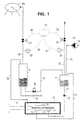
- Figure 1 presents a pressure container 10 serving as a pressure shell. Inside the pressure shell 10 there is placed an electrolytic cell 11 provided with an inlet connector 12 of the electrolytic liquid, with outlet connectors 14 and 13 for hydrogen and oxygen, and respectively with electricity feeding lines 15. The interior of the pressure shell 10 is moreover filled with a liquid, e.g. silicon oil. Electrolytic liquid, such as water, is conducted by means of gravitation into the electrolytic cell 11. The embodiment according to Figure 1 presents water separators 16 and 17 for separating water from hydrogen and oxygen.
- a liquid e.g. silicon oil
- Water is fed into the electrolytic cell 11 from a water pipe 18 and pump 19 through the pressure shell 10 through a water inlet line 20 conducted into the water separator 17 of the oxygen gas and further therefrom through a water inlet line 21 and a back pressure valve 22 positioned therein into an inlet connector 12, and further, into the electrolytic cell 11.
- the oxygen gas produced in the electrolytic cell 11 is conducted through an oxygen outlet connector 13 and an oxygen outlet line 23 to the water separator 17 of oxygen.
- the water following the oxygen gas is separated in the water separator 17 and returns into the electrolytic cell 11 through line 21.
- the hydrogen gas produced in the electrolytic cell 11 is conducted through a hydrogen outlet connector 14 and a hydrogen outlet line 25 to a water separator 16 of the hydrogen gas.
- a hydrogen outlet line 28 provided with a pressure sensor 26 and a valve 27 leads to a hydrogen gas storage container 29.
- a pipe 24 transmitting pressure is led from the water separator 16 to the interior space of the pressure shell 10 for pressurizing thereof.
- a water pipe 31 provided with a valve 30 is conducted from the water separator 16 of the hydrogen gas to the water separator 17 of the oxygen gas, whereby the water following the hydrogen gas can be returned to the electrolytic cell 11 in the above-described manner.
- the oxygen gas is conducted from the water separator 17 to the oxygen outlet line 32 and further for instance into an oxygen container (not shown) when also the oxygen is stored for later use.
- the oxygen outlet line 32 is provided with a pressure sensor 33 and a valve 34.
- the pressure control in the apparatus as shown in Figure 1 can be accomplished preferably so that a pressure controller 35 has been connected with signal leads 36 and 37 to hydrogen and oxygen pressure sensors 26,33 and according to the signal provided by said pressure sensors 26,33, the pressure controller 35 opens and shuts through signal line 38,39 the valves 34,27 in the oxygen and hydrogen outlet lines 32,28.
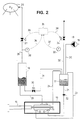
- FIG 2 presents an apparatus according to figure 1 modified so that oxygen is used for pressurizing.
- the apparatus according to the invention is otherwise similar as in figure 1, except that the oxygen outlet pipe 24 is conducted into the pressure shell 10 from the water separator for oxygen.
Landscapes
- Chemical & Material Sciences (AREA)
- Engineering & Computer Science (AREA)
- Chemical Kinetics & Catalysis (AREA)
- Electrochemistry (AREA)
- Materials Engineering (AREA)
- Metallurgy (AREA)
- Organic Chemistry (AREA)
- Inorganic Chemistry (AREA)
- Electrolytic Production Of Non-Metals, Compounds, Apparatuses Therefor (AREA)
- Catalysts (AREA)
- Oxygen, Ozone, And Oxides In General (AREA)
- Hydrogen, Water And Hydrids (AREA)
Claims (7)
- Appareil d'électrolyse pour produire de l'hydrogène en décomposant un liquide électrolytique à l'aide de l'électricité en hydrogène et en oxygène dans une cellule électrolytique sous pression (11), placée à l'intérieur d'une enveloppe sous pression (10) remplie d'un liquide, caractérisé en ce que la cellule électrolytique fermée (11) est sous pression avec un gaz produit dans l'électrolyse, en ce que l'enveloppe de pression (10) communique avec une source de gaz contenant de l'hydrogène ou de l'oxygène sous pression produit dans la cellule électrolytique (11) par une conduite (24) transmettant la pression de la source de gaz au liquide dans l'enveloppe sous pression (10).
- Appareil d'électrolyse selon la revendication 1, caractérisé en ce que le liquide est choisi dans le groupe suivant : graisses et huiles de silicone, huiles fluorées, huiles synthétiques ou à base d'huile brute, eau et leurs mélanges.
- Appareil d'électrolyse selon la revendication 1 ou 2, caractérisé en ce que le gaz est de l'hydrogène.
- Appareil d'électrolyse selon l'une quelconque des revendications 1 à 3, caractérisé en ce que le gaz est de l'oxygène.
- Appareil d'électrolyse selon l'une quelconque des revendications précédentes, caractérisé en ce que l'hydrogène et l'oxygène produits dans la cellule électrolytique (11) sont conduits dans des séparateurs de liquide (16 et 17) pour séparer le liquide d'électrolyse des gaz et les ramener dans la cellule électrolytique (11).
- Appareil d'électrolyse selon la revendication 6, caractérisé en ce qu'au moins l'un des séparateurs de liquide (16 et 17) est placé à l'extérieur de l'enveloppe sous pression (10).
- Appareil d'électrolyse, caractérisé en ce qu'au moins l'un des séparateurs de liquide (16 et 17) est placé à l'intérieur de l'enveloppe sous pression (10).
Applications Claiming Priority (3)
| Application Number | Priority Date | Filing Date | Title |
|---|---|---|---|
| FI923904 | 1992-08-31 | ||
| FI923904A FI90569C (fi) | 1992-08-31 | 1992-08-31 | Elektrolyysilaitteisto vedyn tuottamiseksi |
| PCT/FI1993/000343 WO1994005830A1 (fr) | 1992-08-31 | 1993-08-31 | Appareil d'electrolyse pour la production d'hydrogene |
Publications (3)
| Publication Number | Publication Date |
|---|---|
| EP0656959A1 EP0656959A1 (fr) | 1995-06-14 |
| EP0656959B1 true EP0656959B1 (fr) | 1997-04-16 |
| EP0656959B2 EP0656959B2 (fr) | 2004-11-10 |
Family
ID=8535790
Family Applications (1)
| Application Number | Title | Priority Date | Filing Date |
|---|---|---|---|
| EP93919347A Expired - Lifetime EP0656959B2 (fr) | 1992-08-31 | 1993-08-31 | Appareil d'electrolyse pour la production d'hydrogene |
Country Status (8)
| Country | Link |
|---|---|
| US (1) | US5665211A (fr) |
| EP (1) | EP0656959B2 (fr) |
| AT (1) | ATE151820T1 (fr) |
| AU (1) | AU4961193A (fr) |
| CA (1) | CA2143448C (fr) |
| DE (1) | DE69309937T3 (fr) |
| FI (1) | FI90569C (fr) |
| WO (1) | WO1994005830A1 (fr) |
Families Citing this family (12)
| Publication number | Priority date | Publication date | Assignee | Title |
|---|---|---|---|---|
| CA2329672C (fr) | 2000-12-27 | 2009-12-22 | Donald W. Kirk | Electrode bifurquee pour utilisation dans des cellules electrolytiques |
| CA2333859A1 (fr) | 2001-02-01 | 2002-08-01 | Donald W. Kirk | Pile de cellules electrochimiques |
| US7559978B2 (en) * | 2005-09-19 | 2009-07-14 | General Electric Company | Gas-liquid separator and method of operation |
| US7727373B2 (en) * | 2006-03-17 | 2010-06-01 | Lawrence Curtin | Hydrogen absorption rod |
| US20070215201A1 (en) * | 2006-03-17 | 2007-09-20 | Lawrence Curtin | Photovoltaic cell with integral light transmitting waveguide in a ceramic sleeve |
| DE102007051230B4 (de) * | 2006-10-23 | 2010-04-08 | SETT Solare Energietechnologien Thüringen GmbH | Elektrolysator |
| EP2060661A1 (fr) * | 2007-11-16 | 2009-05-20 | AccaGen SA | Electrolyser pour produire des substances |
| US9011651B2 (en) | 2010-12-09 | 2015-04-21 | Ut-Battelle, Llc | Apparatus and method for the electrolysis of water |
| TWI465301B (zh) * | 2012-09-25 | 2014-12-21 | 南臺科技大學 | 多孔性氧化鋁模板之製作裝置 |
| DE102018213404A1 (de) * | 2018-08-09 | 2020-02-13 | Siemens Aktiengesellschaft | Elektrolyseur und Verfahren zum Betreiben eines Elektrolyseurs |
| GB2612067B (en) * | 2021-10-20 | 2025-07-30 | Francis Geary Paul | Pressurised electrolyser |
| DK181935B1 (en) * | 2023-02-22 | 2025-04-03 | Green Hydrogen Systems As | Gas pressure balance method in an electrolyser system, and electrolyser system with a pressure balance valve system |
Family Cites Families (7)
| Publication number | Priority date | Publication date | Assignee | Title |
|---|---|---|---|---|
| DE529068C (de) * | 1928-10-02 | 1933-02-01 | Karl Hoffmann | Zersetzer, insbesondere zur Elektrolyse von Wasser unter Druck |
| DE755942C (de) * | 1940-09-06 | 1954-02-01 | Siemens & Halske A G | Elektrolytische Gewinnung von Wasserstoff und Sauerstoff im Druckzersetzer |
| US3382167A (en) * | 1964-04-01 | 1968-05-07 | Trw Inc | High pressure electrolytic cell module |
| DE2548699C3 (de) * | 1975-10-30 | 1980-06-26 | Linde Ag, 6200 Wiesbaden | Vorrichtung zur Elektrolyse einer Flüssigkeit unter Druck |
| FR2448583A1 (fr) * | 1979-02-09 | 1980-09-05 | Creusot Loire | Perfectionnements a un appareil d'electrolyse de l'eau |
| FR2608715B1 (fr) * | 1986-12-19 | 1989-12-01 | Srti Soc Rech Tech Ind | Procede de prevention de fuite de liquide, et dispositif muni de moyens de mise en oeuvre de ce procede |
| DE4029634A1 (de) * | 1990-09-19 | 1992-03-26 | Linde Ag | Verfahren zum betreiben einer druckelektrolyseanlage |
-
1992
- 1992-08-31 FI FI923904A patent/FI90569C/fi not_active IP Right Cessation
-
1993
- 1993-08-31 WO PCT/FI1993/000343 patent/WO1994005830A1/fr not_active Ceased
- 1993-08-31 CA CA002143448A patent/CA2143448C/fr not_active Expired - Fee Related
- 1993-08-31 DE DE69309937T patent/DE69309937T3/de not_active Expired - Fee Related
- 1993-08-31 AU AU49611/93A patent/AU4961193A/en not_active Abandoned
- 1993-08-31 US US08/392,939 patent/US5665211A/en not_active Expired - Fee Related
- 1993-08-31 AT AT93919347T patent/ATE151820T1/de not_active IP Right Cessation
- 1993-08-31 EP EP93919347A patent/EP0656959B2/fr not_active Expired - Lifetime
Also Published As
| Publication number | Publication date |
|---|---|
| FI90569B (fi) | 1993-11-15 |
| EP0656959B2 (fr) | 2004-11-10 |
| CA2143448A1 (fr) | 1994-03-17 |
| EP0656959A1 (fr) | 1995-06-14 |
| ATE151820T1 (de) | 1997-05-15 |
| DE69309937T2 (de) | 1997-10-16 |
| US5665211A (en) | 1997-09-09 |
| DE69309937D1 (de) | 1997-05-22 |
| FI923904A0 (fi) | 1992-08-31 |
| DE69309937T3 (de) | 2005-04-07 |
| FI90569C (fi) | 1994-02-25 |
| WO1994005830A1 (fr) | 1994-03-17 |
| CA2143448C (fr) | 2000-02-01 |
| AU4961193A (en) | 1994-03-29 |
Similar Documents
| Publication | Publication Date | Title |
|---|---|---|
| EP0656959B1 (fr) | Appareil d'electrolyse pour la production d'hydrogene | |
| CA2143446C (fr) | Methode pour controler la pression dans un appareil d'electrolyse; production d'hydrogene et d'oxygene a l'aide d'un appareil de ce type | |
| US3652431A (en) | Method of operating an electrolysis cell for the production of gases under hydrostatic pressure | |
| US7097748B2 (en) | Electrolyzer pressure equalization system | |
| US6575248B2 (en) | Fuel cell for downhole and subsea power systems | |
| JP2001130901A (ja) | 水素エネルギ供給装置 | |
| US20050109394A1 (en) | Solar electrolysis power co-generation system | |
| MX2011008710A (es) | Celda electrolitica y metodo de uso de ésta. | |
| KR20040080332A (ko) | 고압수소의 제조장치 및 제조방법 | |
| PL241425B1 (pl) | Kontenerowa stacja wytwarzania i dystrybucji wodoru | |
| CN216107236U (zh) | 一种全浸式垂直单元水电解制氢系统 | |
| EP1181398A1 (fr) | Systeme de regulation de pression destine a une pile electrolytique a eau | |
| RU2095474C1 (ru) | Система подачи электролитической жидкости в работающей под давлением электролизной установке | |
| WO1994005829A1 (fr) | Appareil d'electrolyse pour produire de l'hydrogene | |
| CN214890472U (zh) | 一种基于光伏发电制氢的综合加氢站 | |
| CN113755856A (zh) | 一种全浸式垂直单元水电解制氢系统及其使用方法 | |
| EP4484612A1 (fr) | Dispositif pour générer de l'hydrogène gazeux et de l'oxygène gazeux à partir d'eau, et installation destinée à cette fin comprenant ledit dispositif | |
| US20230390724A1 (en) | Photocatalyst suspension reactor for solar fuel formation | |
| Gillis et al. | Survey of hydrogen production and utilization methods. Volume 2. Discussion. Final report | |
| CN1384224A (zh) | 氢能源发生器 | |
| CA1199668A (fr) | Systeme convertisseur d'energie | |
| HK40058478A (en) | Container station for hydrogen production and distribution |
Legal Events
| Date | Code | Title | Description |
|---|---|---|---|
| PUAI | Public reference made under article 153(3) epc to a published international application that has entered the european phase |
Free format text: ORIGINAL CODE: 0009012 |
|
| 17P | Request for examination filed |
Effective date: 19950227 |
|
| AK | Designated contracting states |
Kind code of ref document: A1 Designated state(s): AT CH DE FR GB IT LI SE |
|
| GRAG | Despatch of communication of intention to grant |
Free format text: ORIGINAL CODE: EPIDOS AGRA |
|
| 17Q | First examination report despatched |
Effective date: 19960710 |
|
| GRAH | Despatch of communication of intention to grant a patent |
Free format text: ORIGINAL CODE: EPIDOS IGRA |
|
| GRAH | Despatch of communication of intention to grant a patent |
Free format text: ORIGINAL CODE: EPIDOS IGRA |
|
| GRAA | (expected) grant |
Free format text: ORIGINAL CODE: 0009210 |
|
| AK | Designated contracting states |
Kind code of ref document: B1 Designated state(s): AT CH DE FR GB IT LI SE |
|
| PG25 | Lapsed in a contracting state [announced via postgrant information from national office to epo] |
Ref country code: LI Free format text: LAPSE BECAUSE OF FAILURE TO SUBMIT A TRANSLATION OF THE DESCRIPTION OR TO PAY THE FEE WITHIN THE PRESCRIBED TIME-LIMIT Effective date: 19970416 Ref country code: CH Free format text: LAPSE BECAUSE OF FAILURE TO SUBMIT A TRANSLATION OF THE DESCRIPTION OR TO PAY THE FEE WITHIN THE PRESCRIBED TIME-LIMIT Effective date: 19970416 Ref country code: AT Free format text: LAPSE BECAUSE OF FAILURE TO SUBMIT A TRANSLATION OF THE DESCRIPTION OR TO PAY THE FEE WITHIN THE PRESCRIBED TIME-LIMIT Effective date: 19970416 |
|
| REF | Corresponds to: |
Ref document number: 151820 Country of ref document: AT Date of ref document: 19970515 Kind code of ref document: T |
|
| REG | Reference to a national code |
Ref country code: CH Ref legal event code: EP |
|
| REF | Corresponds to: |
Ref document number: 69309937 Country of ref document: DE Date of ref document: 19970522 |
|
| REG | Reference to a national code |
Ref country code: CH Ref legal event code: NV Representative=s name: R. A. EGLI & CO. PATENTANWAELTE |
|
| ET | Fr: translation filed | ||
| PLBQ | Unpublished change to opponent data |
Free format text: ORIGINAL CODE: EPIDOS OPPO |
|
| PLBI | Opposition filed |
Free format text: ORIGINAL CODE: 0009260 |
|
| PLBF | Reply of patent proprietor to notice(s) of opposition |
Free format text: ORIGINAL CODE: EPIDOS OBSO |
|
| 26 | Opposition filed |
Opponent name: LINDE AKTIENGESELLSCHAFT Effective date: 19980116 |
|
| PLBF | Reply of patent proprietor to notice(s) of opposition |
Free format text: ORIGINAL CODE: EPIDOS OBSO |
|
| PLAW | Interlocutory decision in opposition |
Free format text: ORIGINAL CODE: EPIDOS IDOP |
|
| APAC | Appeal dossier modified |
Free format text: ORIGINAL CODE: EPIDOS NOAPO |
|
| APAE | Appeal reference modified |
Free format text: ORIGINAL CODE: EPIDOS REFNO |
|
| APAC | Appeal dossier modified |
Free format text: ORIGINAL CODE: EPIDOS NOAPO |
|
| RAP2 | Party data changed (patent owner data changed or rights of a patent transferred) |
Owner name: FORTUM OIL AND GAS OY |
|
| REG | Reference to a national code |
Ref country code: CH Ref legal event code: PFA Free format text: NESTE OY TRANSFER- FORTUM OIL AND GAS OY |
|
| REG | Reference to a national code |
Ref country code: GB Ref legal event code: IF02 |
|
| PGFP | Annual fee paid to national office [announced via postgrant information from national office to epo] |
Ref country code: AT Payment date: 20030811 Year of fee payment: 11 |
|
| PGFP | Annual fee paid to national office [announced via postgrant information from national office to epo] |
Ref country code: GB Payment date: 20030827 Year of fee payment: 11 |
|
| PGFP | Annual fee paid to national office [announced via postgrant information from national office to epo] |
Ref country code: CH Payment date: 20031127 Year of fee payment: 11 |
|
| APBU | Appeal procedure closed |
Free format text: ORIGINAL CODE: EPIDOSNNOA9O |
|
| PGFP | Annual fee paid to national office [announced via postgrant information from national office to epo] |
Ref country code: FR Payment date: 20040728 Year of fee payment: 12 |
|
| PGFP | Annual fee paid to national office [announced via postgrant information from national office to epo] |
Ref country code: SE Payment date: 20040817 Year of fee payment: 12 |
|
| PG25 | Lapsed in a contracting state [announced via postgrant information from national office to epo] |
Ref country code: GB Free format text: LAPSE BECAUSE OF NON-PAYMENT OF DUE FEES Effective date: 20040831 |
|
| PUAH | Patent maintained in amended form |
Free format text: ORIGINAL CODE: 0009272 |
|
| STAA | Information on the status of an ep patent application or granted ep patent |
Free format text: STATUS: PATENT MAINTAINED AS AMENDED |
|
| PGFP | Annual fee paid to national office [announced via postgrant information from national office to epo] |
Ref country code: DE Payment date: 20040929 Year of fee payment: 12 |
|
| 27A | Patent maintained in amended form |
Effective date: 20041110 |
|
| AK | Designated contracting states |
Kind code of ref document: B2 Designated state(s): AT CH DE FR GB IT LI SE |
|
| REG | Reference to a national code |
Ref country code: CH Ref legal event code: AEN Free format text: AUFRECHTERHALTUNG DES PATENTES IN GEAENDERTER FORM |
|
| REG | Reference to a national code |
Ref country code: SE Ref legal event code: RPEO |
|
| PLAQ | Examination of admissibility of opposition: information related to despatch of communication + time limit deleted |
Free format text: ORIGINAL CODE: EPIDOSDOPE2 |
|
| PLAR | Examination of admissibility of opposition: information related to receipt of reply deleted |
Free format text: ORIGINAL CODE: EPIDOSDOPE4 |
|
| PLBQ | Unpublished change to opponent data |
Free format text: ORIGINAL CODE: EPIDOS OPPO |
|
| PLAB | Opposition data, opponent's data or that of the opponent's representative modified |
Free format text: ORIGINAL CODE: 0009299OPPO |
|
| GBPC | Gb: european patent ceased through non-payment of renewal fee |
Effective date: 20040831 |
|
| REG | Reference to a national code |
Ref country code: CH Ref legal event code: PL |
|
| R26 | Opposition filed (corrected) |
Opponent name: LINDE AKTIENGESELLSCHAFT Effective date: 19980116 |
|
| PG25 | Lapsed in a contracting state [announced via postgrant information from national office to epo] |
Ref country code: IT Free format text: LAPSE BECAUSE OF NON-PAYMENT OF DUE FEES;WARNING: LAPSES OF ITALIAN PATENTS WITH EFFECTIVE DATE BEFORE 2007 MAY HAVE OCCURRED AT ANY TIME BEFORE 2007. THE CORRECT EFFECTIVE DATE MAY BE DIFFERENT FROM THE ONE RECORDED. Effective date: 20050831 |
|
| PG25 | Lapsed in a contracting state [announced via postgrant information from national office to epo] |
Ref country code: SE Free format text: LAPSE BECAUSE OF NON-PAYMENT OF DUE FEES Effective date: 20050901 |
|
| APAH | Appeal reference modified |
Free format text: ORIGINAL CODE: EPIDOSCREFNO |
|
| ET3 | Fr: translation filed ** decision concerning opposition | ||
| PG25 | Lapsed in a contracting state [announced via postgrant information from national office to epo] |
Ref country code: DE Free format text: LAPSE BECAUSE OF NON-PAYMENT OF DUE FEES Effective date: 20060301 |
|
| PG25 | Lapsed in a contracting state [announced via postgrant information from national office to epo] |
Ref country code: FR Free format text: LAPSE BECAUSE OF NON-PAYMENT OF DUE FEES Effective date: 20060428 |
|
| EUG | Se: european patent has lapsed | ||
| REG | Reference to a national code |
Ref country code: FR Ref legal event code: ST Effective date: 20060428 |