EP0657018B1 - Dispositif et procede de mesure sans contact de revetements internes de tuyaux de fonte - Google Patents
Dispositif et procede de mesure sans contact de revetements internes de tuyaux de fonte Download PDFInfo
- Publication number
- EP0657018B1 EP0657018B1 EP94920505A EP94920505A EP0657018B1 EP 0657018 B1 EP0657018 B1 EP 0657018B1 EP 94920505 A EP94920505 A EP 94920505A EP 94920505 A EP94920505 A EP 94920505A EP 0657018 B1 EP0657018 B1 EP 0657018B1
- Authority
- EP
- European Patent Office
- Prior art keywords
- sensor
- unit
- calibrating
- measuring
- pipe
- Prior art date
- Legal status (The legal status is an assumption and is not a legal conclusion. Google has not performed a legal analysis and makes no representation as to the accuracy of the status listed.)
- Expired - Lifetime
Links
- 238000000034 method Methods 0.000 title claims description 14
- 229910001018 Cast iron Inorganic materials 0.000 title claims description 8
- 238000000576 coating method Methods 0.000 title description 21
- 239000011248 coating agent Substances 0.000 title description 18
- 238000005259 measurement Methods 0.000 claims description 31
- 239000002184 metal Substances 0.000 claims description 18
- 229910052751 metal Inorganic materials 0.000 claims description 18
- 230000004044 response Effects 0.000 claims description 7
- 239000011344 liquid material Substances 0.000 claims description 5
- 238000006073 displacement reaction Methods 0.000 claims description 4
- 230000006870 function Effects 0.000 description 14
- 239000011083 cement mortar Substances 0.000 description 9
- 239000004568 cement Substances 0.000 description 5
- 238000004519 manufacturing process Methods 0.000 description 5
- 230000007423 decrease Effects 0.000 description 2
- 230000001939 inductive effect Effects 0.000 description 2
- 239000004570 mortar (masonry) Substances 0.000 description 2
- 230000003287 optical effect Effects 0.000 description 2
- 230000035515 penetration Effects 0.000 description 2
- 238000013459 approach Methods 0.000 description 1
- 238000004364 calculation method Methods 0.000 description 1
- 238000005119 centrifugation Methods 0.000 description 1
- 238000005253 cladding Methods 0.000 description 1
- 239000003086 colorant Substances 0.000 description 1
- 238000010276 construction Methods 0.000 description 1
- 238000010168 coupling process Methods 0.000 description 1
- 230000006866 deterioration Effects 0.000 description 1
- 238000010586 diagram Methods 0.000 description 1
- 230000000694 effects Effects 0.000 description 1
- 238000009434 installation Methods 0.000 description 1
- 239000000463 material Substances 0.000 description 1
- 238000002844 melting Methods 0.000 description 1
- 230000008018 melting Effects 0.000 description 1
- 239000007769 metal material Substances 0.000 description 1
- 239000012811 non-conductive material Substances 0.000 description 1
- 230000035699 permeability Effects 0.000 description 1
- 230000008569 process Effects 0.000 description 1
- 238000005316 response function Methods 0.000 description 1
- 238000002604 ultrasonography Methods 0.000 description 1
- XLYOFNOQVPJJNP-UHFFFAOYSA-N water Substances O XLYOFNOQVPJJNP-UHFFFAOYSA-N 0.000 description 1
Images

Classifications
-
- G—PHYSICS
- G01—MEASURING; TESTING
- G01B—MEASURING LENGTH, THICKNESS OR SIMILAR LINEAR DIMENSIONS; MEASURING ANGLES; MEASURING AREAS; MEASURING IRREGULARITIES OF SURFACES OR CONTOURS
- G01B21/00—Measuring arrangements or details thereof, where the measuring technique is not covered by the other groups of this subclass, unspecified or not relevant
- G01B21/02—Measuring arrangements or details thereof, where the measuring technique is not covered by the other groups of this subclass, unspecified or not relevant for measuring length, width, or thickness
- G01B21/08—Measuring arrangements or details thereof, where the measuring technique is not covered by the other groups of this subclass, unspecified or not relevant for measuring length, width, or thickness for measuring thickness
-
- G—PHYSICS
- G01—MEASURING; TESTING
- G01B—MEASURING LENGTH, THICKNESS OR SIMILAR LINEAR DIMENSIONS; MEASURING ANGLES; MEASURING AREAS; MEASURING IRREGULARITIES OF SURFACES OR CONTOURS
- G01B11/00—Measuring arrangements characterised by the use of optical techniques
- G01B11/02—Measuring arrangements characterised by the use of optical techniques for measuring length, width or thickness
- G01B11/06—Measuring arrangements characterised by the use of optical techniques for measuring length, width or thickness for measuring thickness ; e.g. of sheet material
- G01B11/0616—Measuring arrangements characterised by the use of optical techniques for measuring length, width or thickness for measuring thickness ; e.g. of sheet material of coating
-
- G—PHYSICS
- G01—MEASURING; TESTING
- G01B—MEASURING LENGTH, THICKNESS OR SIMILAR LINEAR DIMENSIONS; MEASURING ANGLES; MEASURING AREAS; MEASURING IRREGULARITIES OF SURFACES OR CONTOURS
- G01B7/00—Measuring arrangements characterised by the use of electric or magnetic techniques
- G01B7/02—Measuring arrangements characterised by the use of electric or magnetic techniques for measuring length, width or thickness
- G01B7/023—Measuring arrangements characterised by the use of electric or magnetic techniques for measuring length, width or thickness for measuring distance between sensor and object
-
- G—PHYSICS
- G01—MEASURING; TESTING
- G01B—MEASURING LENGTH, THICKNESS OR SIMILAR LINEAR DIMENSIONS; MEASURING ANGLES; MEASURING AREAS; MEASURING IRREGULARITIES OF SURFACES OR CONTOURS
- G01B7/00—Measuring arrangements characterised by the use of electric or magnetic techniques
- G01B7/02—Measuring arrangements characterised by the use of electric or magnetic techniques for measuring length, width or thickness
- G01B7/06—Measuring arrangements characterised by the use of electric or magnetic techniques for measuring length, width or thickness for measuring thickness
- G01B7/10—Measuring arrangements characterised by the use of electric or magnetic techniques for measuring length, width or thickness for measuring thickness using magnetic means, e.g. by measuring change of reluctance
- G01B7/105—Measuring arrangements characterised by the use of electric or magnetic techniques for measuring length, width or thickness for measuring thickness using magnetic means, e.g. by measuring change of reluctance for measuring thickness of coating
-
- G—PHYSICS
- G01—MEASURING; TESTING
- G01D—MEASURING NOT SPECIALLY ADAPTED FOR A SPECIFIC VARIABLE; ARRANGEMENTS FOR MEASURING TWO OR MORE VARIABLES NOT COVERED IN A SINGLE OTHER SUBCLASS; TARIFF METERING APPARATUS; MEASURING OR TESTING NOT OTHERWISE PROVIDED FOR
- G01D1/00—Measuring arrangements giving results other than momentary value of variable, of general application
- G01D1/16—Measuring arrangements giving results other than momentary value of variable, of general application giving a value which is a function of two or more values, e.g. product or ratio
Definitions
- the present invention relates to the measurement without contact of the thickness of internal coatings in fresh cement mortar for metal pipes, especially in melting.
- the internal coating of metal pipes can be performed by centrifugation of a tubular layer a liquid material capable of hardening, in particular of cement or concrete mortar.
- a contact type measuring device Eddy capable of giving the distance between a coil inducing high frequency currents and the part to control.
- the currents induced in it vary and modify the impedance of the coil, which allows a direct impedance / distance relationship.
- a method of the ultrasonic type, implemented from the outside of the pipe, taking into account differences in acoustic impedance between materials, do not not allow to determine both the thickness of the cast iron and the thickness of the cement mortar.
- DE-A-3701558 discloses an inductive and optical measurement device for determine a coating thickness on a flat support.
- Document EP-A-402527 describes a device and a method for contactless measurement coating thickness of a non-conductive material, using laser sensors and eddy current sensors.
- the object of the invention is to provide a method for measuring the thickness of internal coatings liquid materials which can harden in pipes without damaging its appearance.
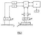
- the non-contact thickness measurement device in Fig. 1 comprises two identical sensor blocks BC1, BC2.
- Block BC1 consists of a current sensor Eddy 1 connected to a current generator and output amplifier 2 and a laser diode sensor 3 connected to an output generator-amplifier 4.
- the BC2 block has the same components as the block BC1, namely an eddy current sensor la and a laser diode sensor 3a each connected to a generator-amplifier 2a, 4a.
- eddy current sensors are dictated by the measurement range in which we want evolve, that is to say a distance at least equal to that the thickness of the cement mortar plus a distance mechanical non-contact with cement mortar in taking into account the variation in thickness of the mortar cement and also a minimum distance related to the rounding of the pipe.
- the metallurgical structure of the part is likely to influence the distance measurement.
- This calibration is performed for each part measured before laying the cement mortar coating.
- laser diode sensors are dictated also by a measurement range capable of giving the maximum thickness of the cement mortar in all case, and by their ability to "see” all the colors of the cement mortar (white, light gray, light brown) wet (color and power emitted).
- An optical sensor laser triangulation eliminates parameters disruptive such as concrete color and deflection of the laser spot on a water slide.
- the inclination of the surface controlled by relative to the sensor axis also influences the measurement of laser sensor.
- the laser sensor is calibrated from way known only once in the laboratory.
- the eddy current sensor 1 and the laser diode 3 both detect the metal surface uncoated and in block BC2, which constitutes the block of measurement, the eddy current sensor 1a is sensitive on the surface of the cast iron pipe F while the sensor laser diode 3a detects the surface of the coating R of the pipe of cast iron.
- the measuring device is implemented industrially on the pipe production line and for location and cadence reasons, we use two sensor blocks, block BC1 for the calibration function, and block BC2 for the measurement function.
- the analog measurement signals output from two blocks BC1, BC2 are recorded by an acquisition card analog-digital 5 (12-bit likely record at an acquisition frequency of 50 Hz and with ⁇ 10 V differential measurement ranges).
- a computer or processing unit 6 and its keyboard 7 are connected to the acquisition card 5 and thus complete the measuring device.
- Fig. 2 shows the pair of sensors of the block BC1, ensuring the calibration function on the surface metallic only.
- the measurement by the laser diode sensor 3 is used to know the distance D precisely, because we know already perfectly the distance-voltage function of the sensor laser diode whatever the structure parameters, roughness, etc. of the surface observed.
- the laser diode sensor has already done subject to calibration.
- Fig. 3 shows the pair of sensors of the BC2 block measurement.
- this block includes a laser diode sensor 3a for measuring the distance D1 between the surface 8a common to the two sensors and the surface R of the concrete cladding, and a current sensor Eddy which simultaneously measures the distance D2 between the surface 8a and the metal wall F for the same point.
- a laser diode sensor 3a for measuring the distance D1 between the surface 8a common to the two sensors and the surface R of the concrete cladding
- a current sensor Eddy which simultaneously measures the distance D2 between the surface 8a and the metal wall F for the same point.
- the first step marked A is calibration on the uncoated metal pipe F, using the block BC1 of sensors described with reference to Fig. 2 introduced into this pipe.
- BC1 calibration block is moved only vertically to establish the distance-voltage function of the eddy current sensor.
- the third step C consists in introducing the block BC2 in the coated pipe and to be measured the thickness of the coating R using this measuring block described with reference to Fig. 3.
- the BC2 sensor block can perform a vertical movement to adapt to all diameters of pipes and longitudinal to measure the thickness profile concrete along the entire length of the pipe.
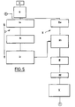
- the algorithm of Fig. 5 implemented by the processing unit 6 makes it possible to process the measurements supplied by the sensor blocks BC1, BC2, in order to obtain a thickness profile for each pipe undergoing three steps described with reference to Fig. 4, noted in order A, B, C.
- Treatment phase I during stage A pipe calibration by the sensor block BC1 is secured in three steps.
- the distance f (voltage) function is then memorized for the pipe considered, here pipe N + 2 at course of step Ic. Note that the distance functions pipes N + 1 and N have already been stored at this time previous similar operations.
Landscapes
- Physics & Mathematics (AREA)
- General Physics & Mathematics (AREA)
- Measurement Of Length, Angles, Or The Like Using Electric Or Magnetic Means (AREA)
- Length Measuring Devices By Optical Means (AREA)
Description
- un bloc destiné à être introduit dans un tuyau dont on veut mesurer l'épaisseur du revêtement, ledit bloc étant formé de deux capteurs, un premier capteur pour mesurer la distance du bloc à la surface métallique du tuyau et un second capteur pour mesurer la distance du bloc à la surface du revêtement, et
- des moyens de traitement des données de sortie du bloc de capteurs en vue de déterminer l'épaisseur du revêtement à partir des données délivrées par les deux capteurs.
- la Fig.1 représente un schéma d'ensemble d'un dispositif selon l'invention de mesure d'épaisseur d'un revêtement en mortier de ciment d'un tuyau;
- la Fig.2 représente schématiquement un premier bloc de capteurs du dispositif de la Fig.1 destiné à l'étalonnage du dispositif;
- la Fig.3 représente schématiquement un second bloc de capteurs du dispositif de la Fig.1, destiné à effectuer les mesures;
- la Fig.4 représente schématiquement trois étapes de production de tuyaux à revêtement interne en ciment au cours desquelles on utilise le dispositif de mesure suivant l'invention; et
- la Fig.5 représente un algorithme de traitement des signaux du dispositif de mesure de la Fig.1.
Claims (8)
- Dispositif de mesure sans contact de l'épaisseur de revêtements internes, en matériaux liquides susceptibles de durcir, de tuyaux métalliques et notamment de tuyaux en fonte, du type comportant:caractérisé en ce que les moyens d'étalonnage comprennent un bloc de capteurs (BC1) d'étalonnage du capteur (1a) à courants de Foucault du bloc de capteurs de mesure (BC2), ledit bloc d'étalonnage étant également relié aux moyens (5,6,7) de traitement de données.un bloc (BC2) de mesure formé de deux capteurs, un premier capteur (1a), à courant de Foucault pour mesurer la distance du bloc à la surface métallique et un second capteur (3a) à diode laser pour mesurer la distance du bloc à la surface du revêtement,des moyens (5,6,7) de traitement des données de sortie du bloc de capteurs en vue de déterminer l'épaisseur du revêtement à partir des données délivrées par les deux capteurs (1a,3a), et des moyens d'étalonnage du premier capteur (1a) à courants de Foucault du bloc de capteur de mesure (BC2),
- Dispositif selon la revendication 1, caractérisé en ce que le bloc de capteurs (BC1) d'étalonnage comporte un premier capteur (1) à courants de Foucault destiné à délivrer des tensions correspondant à des distances du bloc à la surface métallique (F) d'un tuyau, identique au premier capteur (1a) du bloc (BC2) de mesure et un deuxième capteur (3) à diode laser de mesure de la distance du bloc à la surface libre dudit tuyau non revêtu.
- Dispositif suivant l'une quelconque des revendications 1 à 2, caractérisé en ce que les moyens d'étalonnage comprennent le bloc de mesure (BC2) utilisé tour à tour comme bloc d'étalonnage et comme bloc de mesure.
- Dispositif selon l'une quelconque des revendications précédentes, caractérisé en ce que les moyens de traitement sont une carte d'acquisition analogique-numérique (5), un ordinateur, ou unité de traitement (6) et son clavier (7).
- Procédé de mesure sans contact de l'épaisseur de revêtements internes en matériaux liquides susceptibles de durcir, de tuyaux métalliques notamment de tuyaux en fonte, à l'aide du dispositif selon l'une quelconque des revendications précédentes, caractérisé en ce que :l'on introduit un bloc de capteurs de mesure (BC2) dans un tuyau revêtu, on mesure à l'aide du premier capteur (1a), la distance (D2) à la surface métallique et à l'aide du deuxième capteur (3a) du bloc, la distance (D1) à la surface libre du revêtement, et on calcule l'épaisseur (e) du revêtement par différence entre les deux distances précitées,le premier capteur (1a) étant un capteur à courants de Foucault, il comporte en outre une phase d'étalonnage de ce capteur, au cours de laquelle on introduit dans le tuyau non revêtu un bloc de capteurs (BC1; BC2), on déplace le bloc de capteurs transversalement à l'axe du tuyau, on mesure pour chaque déplacement du bloc de capteurs la distance de celui-ci à la surface métallique du tuyau à l'aide du capteur à diode laser (3; 3a) et la réponse en tension du capteur à courants de Foucault correspondante (1;1a), on transmet les données obtenues aux moyens de traitement (5,6) afin d'obtenir la fonction distance = f(tension) du capteur à courants de Foucault (1a) et on retire le bloc de capteurs (BC1; BC2) afin de permettre la pose d'un revêtement sur la surface interne du tuyau.
- Procédé selon la revendication 5, caractérisé en ce que la fonction distance f=(tension) est obtenue par les moyens de traitement des données mesurées lors de la phase d'étalonnage au moyen d'une approximation de cette fonction à un polynôme de degré (4) par la méthode des moindres carrés.
- Procédé suivant la revendication 5, caractérisé en ce que le bloc de capteurs utilisé au cours de la phase d'étalonnage est le bloc de capteurs de mesure (BC2).
- Procédé suivant la revendication 5, caractérisé en ce que le bloc de capteurs utilisé au cours de la phase d'étalonnage est le bloc de capteurs d'étalonnage (BC1).
Applications Claiming Priority (3)
| Application Number | Priority Date | Filing Date | Title |
|---|---|---|---|
| FR9308010 | 1993-06-30 | ||
| FR9308010A FR2707109B1 (fr) | 1993-06-30 | 1993-06-30 | Dispositif et procédé de mesure sans contact de revêtements internes de tuyaux de fonte. |
| PCT/FR1994/000758 WO1995001550A1 (fr) | 1993-06-30 | 1994-06-23 | Dispositif et procede de mesure sans contact de revetements internes de tuyaux de fonte |
Publications (2)
| Publication Number | Publication Date |
|---|---|
| EP0657018A1 EP0657018A1 (fr) | 1995-06-14 |
| EP0657018B1 true EP0657018B1 (fr) | 1998-03-18 |
Family
ID=9448757
Family Applications (1)
| Application Number | Title | Priority Date | Filing Date |
|---|---|---|---|
| EP94920505A Expired - Lifetime EP0657018B1 (fr) | 1993-06-30 | 1994-06-23 | Dispositif et procede de mesure sans contact de revetements internes de tuyaux de fonte |
Country Status (5)
| Country | Link |
|---|---|
| EP (1) | EP0657018B1 (fr) |
| DE (1) | DE69409071T2 (fr) |
| ES (1) | ES2114207T3 (fr) |
| FR (1) | FR2707109B1 (fr) |
| WO (1) | WO1995001550A1 (fr) |
Cited By (1)
| Publication number | Priority date | Publication date | Assignee | Title |
|---|---|---|---|---|
| CN111023960A (zh) * | 2019-12-31 | 2020-04-17 | 新余学院 | 一种基于透明导电薄膜电极材料的非接触式漆膜厚度无损检测系统及检测方法 |
Families Citing this family (8)
| Publication number | Priority date | Publication date | Assignee | Title |
|---|---|---|---|---|
| DE19501642B4 (de) * | 1995-01-20 | 2008-01-17 | Robert Bosch Gmbh | Verfahren zur berührungslosen Abstandsmessung |
| FR2752294B1 (fr) * | 1996-08-12 | 1998-11-27 | Lorraine Laminage | Procede et dispositif de mesure en continu d'epaisseur de revetement isolant |
| DE10001516B4 (de) * | 2000-01-15 | 2014-05-08 | Alstom Technology Ltd. | Zerstörungsfreies Verfahren zur Bestimmung der Schichtdicke einer metallischen Schutzschicht auf einem metallischen Grundmaterial |
| JP5754833B2 (ja) * | 2010-03-23 | 2015-07-29 | 株式会社栗本鐵工所 | 内径測定装置 |
| EP2791617A4 (fr) * | 2011-12-14 | 2014-12-10 | Daprox Ab | Dispositif de mesure de l'épaisseur d'un matériau |
| CN104613883B (zh) * | 2015-02-11 | 2017-11-17 | 南通大学 | 金属薄板印刷涂层的湿膜厚度差分测量及均匀性评估方法 |
| CN111486782A (zh) * | 2019-01-26 | 2020-08-04 | 保定长空科技有限公司 | 一种玻璃钢涂层膜厚非接触式监测设备 |
| CN120385273A (zh) * | 2025-04-16 | 2025-07-29 | 清华大学 | 一种非接触式湿膜厚度检测方法、装置及电子设备 |
Family Cites Families (4)
| Publication number | Priority date | Publication date | Assignee | Title |
|---|---|---|---|---|
| CH670504A5 (fr) * | 1986-11-25 | 1989-06-15 | Battelle Memorial Institute | |
| DE3701558A1 (de) * | 1987-01-21 | 1988-08-04 | Buehler Ag Geb | Vorrichtung zum bestimmen der schichtdicke |
| DE3919131A1 (de) * | 1989-06-12 | 1990-12-13 | Tzn Forschung & Entwicklung | Vorrichtung und verfahren zur beruehrungslosen messung der schichtdicke eines nichtleitenden materials sowie verwendung der vorrichtung zur messung kunststoffbeschichteter metallteile |
| JP2622885B2 (ja) * | 1989-10-09 | 1997-06-25 | 明産株式会社 | シート厚さ測定装置 |
-
1993
- 1993-06-30 FR FR9308010A patent/FR2707109B1/fr not_active Expired - Fee Related
-
1994
- 1994-06-23 ES ES94920505T patent/ES2114207T3/es not_active Expired - Lifetime
- 1994-06-23 DE DE69409071T patent/DE69409071T2/de not_active Expired - Lifetime
- 1994-06-23 EP EP94920505A patent/EP0657018B1/fr not_active Expired - Lifetime
- 1994-06-23 WO PCT/FR1994/000758 patent/WO1995001550A1/fr not_active Ceased
Cited By (2)
| Publication number | Priority date | Publication date | Assignee | Title |
|---|---|---|---|---|
| CN111023960A (zh) * | 2019-12-31 | 2020-04-17 | 新余学院 | 一种基于透明导电薄膜电极材料的非接触式漆膜厚度无损检测系统及检测方法 |
| CN111023960B (zh) * | 2019-12-31 | 2021-04-27 | 新余学院 | 一种基于透明导电薄膜电极材料的非接触式漆膜厚度无损检测系统及检测方法 |
Also Published As
| Publication number | Publication date |
|---|---|
| ES2114207T3 (es) | 1998-05-16 |
| WO1995001550A1 (fr) | 1995-01-12 |
| FR2707109A1 (fr) | 1995-01-06 |
| FR2707109B1 (fr) | 1995-09-01 |
| EP0657018A1 (fr) | 1995-06-14 |
| DE69409071T2 (de) | 1998-07-16 |
| DE69409071D1 (de) | 1998-04-23 |
Similar Documents
| Publication | Publication Date | Title |
|---|---|---|
| EP0657018B1 (fr) | Dispositif et procede de mesure sans contact de revetements internes de tuyaux de fonte | |
| FR3070499B1 (fr) | Procede de determination des variations de contraintes au cours du temps d'une conduite sous-marine de transport de fluides | |
| JP2912157B2 (ja) | 物体の温度測定方法 | |
| US5525903A (en) | Eddy current method of acquiring the surface layer properties of a metallic target | |
| Grunwald et al. | Fibre optic refractive index microsensor based on white-light SPR excitation | |
| Madding | Emissivity measurement and temperature correction accuracy considerations | |
| CN102170995B (zh) | 用于测量管件焊接接头的方法和设备 | |
| CN1094191C (zh) | 金属基体表面非金属涂层厚度非接触测量方法及其装置 | |
| BE1016251A3 (fr) | Procede ameliore et appareil pour la mesure de l'epaisseur d'une couche d'oxyde. | |
| JPH0358443B2 (fr) | ||
| Le Roux et al. | Quantitative assessment of the interfacial roughness in multi-layered materials using image analysis: Application to oxidation in ceramic-based materials | |
| FR2465995A1 (fr) | Procede de mesure de l'epaisseur de la paroi d'un tube | |
| WO1988004028A1 (fr) | Procede pour detecter des variations d'epaisseur dans la paroi d'un corps tubulaire conducteur de l'electricite | |
| JP2008014959A (ja) | コーティング部材の界面欠陥検査方法 | |
| WO2007071944A1 (fr) | Appareil et procede de determination de caracteristiques de surface | |
| EP1155313B1 (fr) | Procede et dispositif de mesure in situ de la distance entre deux elements donnes dans une conduite tubulaire | |
| JP2010256277A (ja) | 被測定物の外形測定方法及び外形測定装置 | |
| FR2459476A1 (fr) | Procede et dispositif d'inspection de produits metalliques par courants de foucault | |
| EP1136820A1 (fr) | Dispositif pour effectuer le contrôle d'une pièce par courants de Foucault | |
| Kayacan et al. | Experimental determination of thermal emissivities for Ti6Al4V in SLM method | |
| JP2000171231A (ja) | 管体の形状測定方法および装置 | |
| EP0580485A1 (fr) | Système de contrôle de canalisations notamment de canalisations en acier nu ou enrobé | |
| WO2009007395A1 (fr) | Systeme, procede, et capteur de controle de l'alteration de materiaux par voie humide | |
| EP0394158A1 (fr) | Procédé et dispositif de contrôle non destructif de matériau magnétique présentant un gradient de structure dans sa partie superficielle | |
| Benatmane et al. | 3D analysis of buried interfaces using interference microscopy |
Legal Events
| Date | Code | Title | Description |
|---|---|---|---|
| PUAI | Public reference made under article 153(3) epc to a published international application that has entered the european phase |
Free format text: ORIGINAL CODE: 0009012 |
|
| AK | Designated contracting states |
Kind code of ref document: A1 Designated state(s): CH DE ES FR GB LI |
|
| 17P | Request for examination filed |
Effective date: 19950712 |
|
| 17Q | First examination report despatched |
Effective date: 19961209 |
|
| GRAG | Despatch of communication of intention to grant |
Free format text: ORIGINAL CODE: EPIDOS AGRA |
|
| GRAG | Despatch of communication of intention to grant |
Free format text: ORIGINAL CODE: EPIDOS AGRA |
|
| GRAG | Despatch of communication of intention to grant |
Free format text: ORIGINAL CODE: EPIDOS AGRA |
|
| GRAH | Despatch of communication of intention to grant a patent |
Free format text: ORIGINAL CODE: EPIDOS IGRA |
|
| GRAH | Despatch of communication of intention to grant a patent |
Free format text: ORIGINAL CODE: EPIDOS IGRA |
|
| GRAA | (expected) grant |
Free format text: ORIGINAL CODE: 0009210 |
|
| AK | Designated contracting states |
Kind code of ref document: B1 Designated state(s): CH DE ES FR GB LI |
|
| REG | Reference to a national code |
Ref country code: CH Ref legal event code: NV Representative=s name: KIRKER & CIE SA Ref country code: CH Ref legal event code: EP |
|
| GBT | Gb: translation of ep patent filed (gb section 77(6)(a)/1977) |
Effective date: 19980319 |
|
| REF | Corresponds to: |
Ref document number: 69409071 Country of ref document: DE Date of ref document: 19980423 |
|
| REG | Reference to a national code |
Ref country code: ES Ref legal event code: FG2A Ref document number: 2114207 Country of ref document: ES Kind code of ref document: T3 |
|
| PLBE | No opposition filed within time limit |
Free format text: ORIGINAL CODE: 0009261 |
|
| STAA | Information on the status of an ep patent application or granted ep patent |
Free format text: STATUS: NO OPPOSITION FILED WITHIN TIME LIMIT |
|
| 26N | No opposition filed | ||
| PGFP | Annual fee paid to national office [announced via postgrant information from national office to epo] |
Ref country code: CH Payment date: 20000516 Year of fee payment: 7 |
|
| PG25 | Lapsed in a contracting state [announced via postgrant information from national office to epo] |
Ref country code: LI Free format text: LAPSE BECAUSE OF NON-PAYMENT OF DUE FEES Effective date: 20010630 Ref country code: CH Free format text: LAPSE BECAUSE OF NON-PAYMENT OF DUE FEES Effective date: 20010630 |
|
| REG | Reference to a national code |
Ref country code: GB Ref legal event code: IF02 |
|
| REG | Reference to a national code |
Ref country code: CH Ref legal event code: PL |
|
| PGFP | Annual fee paid to national office [announced via postgrant information from national office to epo] |
Ref country code: DE Payment date: 20120620 Year of fee payment: 19 |
|
| PGFP | Annual fee paid to national office [announced via postgrant information from national office to epo] |
Ref country code: FR Payment date: 20120619 Year of fee payment: 19 Ref country code: GB Payment date: 20120620 Year of fee payment: 19 |
|
| PGFP | Annual fee paid to national office [announced via postgrant information from national office to epo] |
Ref country code: ES Payment date: 20120726 Year of fee payment: 19 |
|
| GBPC | Gb: european patent ceased through non-payment of renewal fee |
Effective date: 20130623 |
|
| REG | Reference to a national code |
Ref country code: DE Ref legal event code: R119 Ref document number: 69409071 Country of ref document: DE Effective date: 20140101 |
|
| REG | Reference to a national code |
Ref country code: FR Ref legal event code: ST Effective date: 20140228 |
|
| PG25 | Lapsed in a contracting state [announced via postgrant information from national office to epo] |
Ref country code: DE Free format text: LAPSE BECAUSE OF NON-PAYMENT OF DUE FEES Effective date: 20140101 Ref country code: GB Free format text: LAPSE BECAUSE OF NON-PAYMENT OF DUE FEES Effective date: 20130623 |
|
| PG25 | Lapsed in a contracting state [announced via postgrant information from national office to epo] |
Ref country code: FR Free format text: LAPSE BECAUSE OF NON-PAYMENT OF DUE FEES Effective date: 20130701 |
|
| REG | Reference to a national code |
Ref country code: ES Ref legal event code: FD2A Effective date: 20140707 |
|
| PG25 | Lapsed in a contracting state [announced via postgrant information from national office to epo] |
Ref country code: ES Free format text: LAPSE BECAUSE OF NON-PAYMENT OF DUE FEES Effective date: 20130624 |