EP0657064B1 - Wicklungsträgerkörper für transformatoren/drosselspulen mit supraleitern - Google Patents
Wicklungsträgerkörper für transformatoren/drosselspulen mit supraleitern Download PDFInfo
- Publication number
- EP0657064B1 EP0657064B1 EP94908825A EP94908825A EP0657064B1 EP 0657064 B1 EP0657064 B1 EP 0657064B1 EP 94908825 A EP94908825 A EP 94908825A EP 94908825 A EP94908825 A EP 94908825A EP 0657064 B1 EP0657064 B1 EP 0657064B1
- Authority
- EP
- European Patent Office
- Prior art keywords
- support body
- winding
- envelope surface
- pct
- tape
- Prior art date
- Legal status (The legal status is an assumption and is not a legal conclusion. Google has not performed a legal analysis and makes no representation as to the accuracy of the status listed.)
- Expired - Lifetime
Links
- 238000004804 winding Methods 0.000 title claims abstract description 53
- 239000002887 superconductor Substances 0.000 title abstract description 6
- 239000004020 conductor Substances 0.000 claims description 16
- 238000000034 method Methods 0.000 description 4
- 230000000694 effects Effects 0.000 description 2
- 230000004907 flux Effects 0.000 description 2
- 230000006978 adaptation Effects 0.000 description 1
- 230000004323 axial length Effects 0.000 description 1
- 239000011230 binding agent Substances 0.000 description 1
- 230000002860 competitive effect Effects 0.000 description 1
- 238000006073 displacement reaction Methods 0.000 description 1
- 238000009413 insulation Methods 0.000 description 1
- 239000000463 material Substances 0.000 description 1
- 239000011159 matrix material Substances 0.000 description 1
- 230000000737 periodic effect Effects 0.000 description 1
Images
Classifications
-
- H—ELECTRICITY
- H01—ELECTRIC ELEMENTS
- H01F—MAGNETS; INDUCTANCES; TRANSFORMERS; SELECTION OF MATERIALS FOR THEIR MAGNETIC PROPERTIES
- H01F27/00—Details of transformers or inductances, in general
- H01F27/28—Coils; Windings; Conductive connections
- H01F27/30—Fastening or clamping coils, windings, or parts thereof together; Fastening or mounting coils or windings on core, casing, or other support
- H01F27/306—Fastening or mounting coils or windings on core, casing or other support
-
- H—ELECTRICITY
- H01—ELECTRIC ELEMENTS
- H01F—MAGNETS; INDUCTANCES; TRANSFORMERS; SELECTION OF MATERIALS FOR THEIR MAGNETIC PROPERTIES
- H01F36/00—Transformers with superconductive windings or with windings operating at cryogenic temperature
-
- Y—GENERAL TAGGING OF NEW TECHNOLOGICAL DEVELOPMENTS; GENERAL TAGGING OF CROSS-SECTIONAL TECHNOLOGIES SPANNING OVER SEVERAL SECTIONS OF THE IPC; TECHNICAL SUBJECTS COVERED BY FORMER USPC CROSS-REFERENCE ART COLLECTIONS [XRACs] AND DIGESTS
- Y02—TECHNOLOGIES OR APPLICATIONS FOR MITIGATION OR ADAPTATION AGAINST CLIMATE CHANGE
- Y02E—REDUCTION OF GREENHOUSE GAS [GHG] EMISSIONS, RELATED TO ENERGY GENERATION, TRANSMISSION OR DISTRIBUTION
- Y02E40/00—Technologies for an efficient electrical power generation, transmission or distribution
- Y02E40/60—Superconducting electric elements or equipment; Power systems integrating superconducting elements or equipment
-
- Y—GENERAL TAGGING OF NEW TECHNOLOGICAL DEVELOPMENTS; GENERAL TAGGING OF CROSS-SECTIONAL TECHNOLOGIES SPANNING OVER SEVERAL SECTIONS OF THE IPC; TECHNICAL SUBJECTS COVERED BY FORMER USPC CROSS-REFERENCE ART COLLECTIONS [XRACs] AND DIGESTS
- Y10—TECHNICAL SUBJECTS COVERED BY FORMER USPC
- Y10S—TECHNICAL SUBJECTS COVERED BY FORMER USPC CROSS-REFERENCE ART COLLECTIONS [XRACs] AND DIGESTS
- Y10S336/00—Inductor devices
- Y10S336/01—Superconductive
Definitions
- the present invention relates to a winding support body with the aid of which the conductor is oriented such that the direction of the magnetic field coincides with the plane of the conductor.
- a superconductor which is to be used in a transformer winding/reactor winding is suitably given the shape of a tape, that is, the width thereof is considerably larger than the thickness.
- the tape preferably consists of a number of superconducting filaments embedded into a metallic matrix. This, however, means that with such a conductor the mechanical strength of the winding is not sufficient to support the magnetic forces which may arise. Therefore, the conductor needs a mechanical support in the form of a winding support body. Since the prior art at present does not comprise transformers/reactors with superconductors, there is also no prior art regarding the design of winding support bodies for such windings.
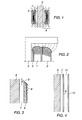
- the magnetic field configuration for two concentric windings 1 and 2 around a limb 3 of a transformer core will have an appearance as shown in Figure 1.
- the substantially axial leakage flux 4 extending between the windings is deflected in a more or less radial direction at the ends of the windings in order to enter the core. This causes the ends of the windings to be traversed by a magnetic flux with a radial component which generates eddy currents in the conductor and causes losses.
- the inward rounding towards the core limb is brought about by rounding off the winding support body 5, which is really not necessary from a mechanical point of view, at the ends towards the core limb, and the outward rounding can be performed with the aid of wedges or linings of different kinds.
- This method entails an increased space requirement, increased radius of the windings resulting in increased losses, and a relatively time-consuming and difficult winding work.
- a winding support body comprises a substantially straight, circular-cylindrical tubular body.
- the body On the side where the winding is to be placed, the body is provided, towards both its ends, with a helical slot along the body with a plane surface having a width equal to the width of the conductor.
- each turn of the slot around the body out towards the ends forms a surface which practically constitutes the envelope surface of a frustum of a cone.
- the angle between a generatrix of the envelope surface of the straight frustum of a cone and the axial centre line of the body increases continuously towards the ends of the body such that the envelope surface at all points coincides with the direction of the magnetic field.
- the mid-portion of the body has a circular-cylindrical envelope surface without slots. Because of the helical slot along the ends of the body, the superconducting tape can be wound continuously in one or more layers along the entire body.
- such a winding support body entails an additional advantage.
- the periodic force with twice the power frequency, which force is proportional to the product of the current intensity in the conductor and the magnitude of the magnetic field in which the conductor occurs, and to which the current-carrying conductor is subjected, is given a direction which is perpendicular to the base at all points. This means that the binder which is used to bind the conductor to the support body is subjected to small stresses.
- FIG. 3 shows in a detailed embodiment a section of the end 6 of a winding support body.
- the cryostat wall is in Figure 3 designated 7 and the superconducting tape of the winding is shown at 8.
- Figure 3 also shows how the angle "v" between a generatrix 9 to the above-mentioned straight frustum of a cone and the axial centre line of the support body increases out towards the ends of the support body. In this way, the support body terminates in a stepped, tapering form towards its ends.
- Figure 4 shows in a section the winding support body 6 in its entire axial length.
- a termination with a stepped tapering form of the slots out towards the other end of the support body, corresponding to the embodiment shown in Figure 3, is also clear from this figure.
- the magnetic field along the mid-portion of the winding extends parallel to the core limb, and therefore the mid-portion of the winding support body has a surface parallel to the core limb.
- This described part of Figure 4 corresponds to the embodiment of a winding support body and a winding in a reactor and the inner winding support body with a winding in a transformer.
- this winding has to be fixed to a corresponding winding support body 10.
- this outer support body will have an inverted shape in relation to a plane half-way between the two support bodies.
- the space 11 between the two windings is intended for any insulation.
- the slot is helical along the ends of the support body such that the superconducting tape can be wound on the support body continuously with the desired number of layers.
Landscapes
- Engineering & Computer Science (AREA)
- Power Engineering (AREA)
- Coils Of Transformers For General Uses (AREA)
- Superconductors And Manufacturing Methods Therefor (AREA)
- Insulation, Fastening Of Motor, Generator Windings (AREA)
Claims (1)
- Wicklungsträgerkörper (6, 10) für eine Wicklung aus Leitern in Gestalt eines supraleitfähigen Bandes (8), dadurch gekennzeichnet, daß der Wicklungsträgerkörper aus einem im wesentlichen geraden kreiszylindrischen rohrförmigen Körper (6) besteht und daß auf der Seite des Körpers, auf welcher die Wicklung aufgebracht wird, und im Bereich der Enden dieses Körpers eine schraubenförmige Rille mit einer ebenen Fläche von der Breite des Bandes (8) in der Weise längs des Körpers vorhanden ist, daß jede Windung der Rille um den Körper praktisch eine Hüllfläche eines geraden abgestumpften Kegels bildet und der Winkel (v) zwischen der Erzeugenden (9) der Hüllfläche und der Mittelachse des Körpers mit jeder Windung in Richtung zu den Enden des Körpers derart zunimmt, daß die Hüllfläche jeder Windung in allen Punkten mit der Richtung des von der Wicklung erregten magnetischen Feldes zusammenfällt.
Applications Claiming Priority (3)
| Application Number | Priority Date | Filing Date | Title |
|---|---|---|---|
| SE9202455 | 1992-08-27 | ||
| SE9202455A SE500238C2 (sv) | 1992-08-27 | 1992-08-27 | Lindningsstomme för en lindning med ledare i form av en supraledande tape |
| PCT/SE1993/000676 WO1994006133A1 (en) | 1992-08-27 | 1993-08-13 | Winding support body for transformers/reactors with superconductors |
Publications (2)
| Publication Number | Publication Date |
|---|---|
| EP0657064A1 EP0657064A1 (de) | 1995-06-14 |
| EP0657064B1 true EP0657064B1 (de) | 1997-10-29 |
Family
ID=20387015
Family Applications (1)
| Application Number | Title | Priority Date | Filing Date |
|---|---|---|---|
| EP94908825A Expired - Lifetime EP0657064B1 (de) | 1992-08-27 | 1993-08-13 | Wicklungsträgerkörper für transformatoren/drosselspulen mit supraleitern |
Country Status (9)
| Country | Link |
|---|---|
| US (1) | US5568114A (de) |
| EP (1) | EP0657064B1 (de) |
| JP (1) | JP3306065B2 (de) |
| AT (1) | ATE159834T1 (de) |
| CA (1) | CA2141970C (de) |
| DE (1) | DE69314961T2 (de) |
| DK (1) | DK0657064T3 (de) |
| SE (1) | SE500238C2 (de) |
| WO (1) | WO1994006133A1 (de) |
Families Citing this family (2)
| Publication number | Priority date | Publication date | Assignee | Title |
|---|---|---|---|---|
| AU2001239019B2 (en) * | 2000-03-21 | 2006-01-19 | S C Power Systems, Inc. | A superconducting transformer |
| AUPQ637600A0 (en) * | 2000-03-21 | 2000-04-15 | Metal Manufactures Limited | A superconducting transformer |
Family Cites Families (5)
| Publication number | Priority date | Publication date | Assignee | Title |
|---|---|---|---|---|
| SE381767B (sv) * | 1974-04-24 | 1975-12-15 | Asea Ab | Direktkyld bandagelindning for transformatorer |
| DE2811504A1 (de) * | 1978-03-16 | 1979-09-27 | Max Planck Gesellschaft | Normal- oder supraleitende magnetspule |
| SE418234B (sv) * | 1979-08-14 | 1981-05-11 | Asea Ab | Krafttransformator eller reaktor |
| US4682134A (en) * | 1985-06-03 | 1987-07-21 | General Electric Company | Conical, unimpregnated winding for MR magnets |
| US5426408A (en) * | 1993-05-07 | 1995-06-20 | The United States Of America As Represented By The Secretary Of The Navy | Ceramic superconducting magnet using stacked modules |
-
1992
- 1992-08-27 SE SE9202455A patent/SE500238C2/sv not_active IP Right Cessation
-
1993
- 1993-08-13 DK DK94908825T patent/DK0657064T3/da active
- 1993-08-13 CA CA002141970A patent/CA2141970C/en not_active Expired - Fee Related
- 1993-08-13 AT AT94908825T patent/ATE159834T1/de active
- 1993-08-13 EP EP94908825A patent/EP0657064B1/de not_active Expired - Lifetime
- 1993-08-13 JP JP50711194A patent/JP3306065B2/ja not_active Expired - Fee Related
- 1993-08-13 WO PCT/SE1993/000676 patent/WO1994006133A1/en not_active Ceased
- 1993-08-13 DE DE69314961T patent/DE69314961T2/de not_active Expired - Lifetime
- 1993-08-27 US US08/373,221 patent/US5568114A/en not_active Expired - Lifetime
Also Published As
| Publication number | Publication date |
|---|---|
| CA2141970A1 (en) | 1994-03-17 |
| JPH08500704A (ja) | 1996-01-23 |
| JP3306065B2 (ja) | 2002-07-24 |
| ATE159834T1 (de) | 1997-11-15 |
| US5568114A (en) | 1996-10-22 |
| SE500238C2 (sv) | 1994-05-09 |
| CA2141970C (en) | 2003-10-21 |
| WO1994006133A1 (en) | 1994-03-17 |
| DE69314961T2 (de) | 1998-06-10 |
| EP0657064A1 (de) | 1995-06-14 |
| SE9202455D0 (sv) | 1992-08-27 |
| DE69314961D1 (de) | 1997-12-04 |
| SE9202455L (sv) | 1994-02-28 |
| DK0657064T3 (da) | 1998-07-20 |
Similar Documents
| Publication | Publication Date | Title |
|---|---|---|
| US4520335A (en) | Transformer with ferromagnetic circuits of unequal saturation inductions | |
| CA1296399C (en) | High-voltage winding for core form power transformers | |
| US6320490B1 (en) | Integrated planar transformer and inductor assembly | |
| US5387894A (en) | Distribution transformers | |
| EP0676776B1 (de) | Kernanordnung für Ringkerntransformator | |
| EP0310813A1 (de) | Geschichteter Kern mit stufenweise gegeneinander versetzten Stosstypen | |
| US5168255A (en) | Three phase transformer | |
| US5568114A (en) | Winding support body for transformers/reactors with superconductors | |
| AU757354B2 (en) | An electric transformer having superconductive coils | |
| EP0870309B1 (de) | Transformator mit supraleitenden wicklungen | |
| US5387891A (en) | Coil configuration having twisted ends and being made of a conductor with superconducting filaments | |
| CA2233802A1 (en) | Bobbin with integral support tabs | |
| EP0339934A2 (de) | Windung fur eine elektrische induktive Vorrichtung | |
| US5508674A (en) | Core-form transformer | |
| CA2082379C (en) | Transformer or reactor cooled by an insulating agent | |
| JP4674457B2 (ja) | 超電導コイル | |
| JPS6461010A (en) | Superconducting transformer | |
| JPS59149014A (ja) | 誘導電器巻線 | |
| JPS60261118A (ja) | 箔巻変圧器 | |
| JPS61264705A (ja) | 超電導コイル | |
| JPH0794343A (ja) | 誘導電器 | |
| RO101236A2 (ro) | Culegator de curent pentru transformatoare cu reglare continua a tensiunii sub sarcina | |
| HK1010419B (en) | Core assembly for toroidal transformer | |
| JPH0475306A (ja) | 変圧器 | |
| JPS6423516A (en) | Superconducting transformer |
Legal Events
| Date | Code | Title | Description |
|---|---|---|---|
| PUAI | Public reference made under article 153(3) epc to a published international application that has entered the european phase |
Free format text: ORIGINAL CODE: 0009012 |
|
| 17P | Request for examination filed |
Effective date: 19950208 |
|
| AK | Designated contracting states |
Kind code of ref document: A1 Designated state(s): AT BE DE DK FR GB |
|
| GRAG | Despatch of communication of intention to grant |
Free format text: ORIGINAL CODE: EPIDOS AGRA |
|
| 17Q | First examination report despatched |
Effective date: 19961008 |
|
| GRAH | Despatch of communication of intention to grant a patent |
Free format text: ORIGINAL CODE: EPIDOS IGRA |
|
| GRAH | Despatch of communication of intention to grant a patent |
Free format text: ORIGINAL CODE: EPIDOS IGRA |
|
| GRAA | (expected) grant |
Free format text: ORIGINAL CODE: 0009210 |
|
| AK | Designated contracting states |
Kind code of ref document: B1 Designated state(s): AT BE DE DK FR GB |
|
| REF | Corresponds to: |
Ref document number: 159834 Country of ref document: AT Date of ref document: 19971115 Kind code of ref document: T |
|
| REF | Corresponds to: |
Ref document number: 69314961 Country of ref document: DE Date of ref document: 19971204 |
|
| ET | Fr: translation filed | ||
| REG | Reference to a national code |
Ref country code: DK Ref legal event code: T3 |
|
| PLBE | No opposition filed within time limit |
Free format text: ORIGINAL CODE: 0009261 |
|
| STAA | Information on the status of an ep patent application or granted ep patent |
Free format text: STATUS: NO OPPOSITION FILED WITHIN TIME LIMIT |
|
| 26N | No opposition filed | ||
| REG | Reference to a national code |
Ref country code: GB Ref legal event code: IF02 |
|
| PGFP | Annual fee paid to national office [announced via postgrant information from national office to epo] |
Ref country code: DK Payment date: 20040813 Year of fee payment: 12 |
|
| PG25 | Lapsed in a contracting state [announced via postgrant information from national office to epo] |
Ref country code: DK Free format text: LAPSE BECAUSE OF NON-PAYMENT OF DUE FEES Effective date: 20050831 |
|
| REG | Reference to a national code |
Ref country code: DK Ref legal event code: EBP |
|
| PGFP | Annual fee paid to national office [announced via postgrant information from national office to epo] |
Ref country code: FR Payment date: 20100824 Year of fee payment: 18 Ref country code: DE Payment date: 20100812 Year of fee payment: 18 Ref country code: AT Payment date: 20100812 Year of fee payment: 18 |
|
| PGFP | Annual fee paid to national office [announced via postgrant information from national office to epo] |
Ref country code: GB Payment date: 20100811 Year of fee payment: 18 |
|
| PGFP | Annual fee paid to national office [announced via postgrant information from national office to epo] |
Ref country code: BE Payment date: 20100818 Year of fee payment: 18 |
|
| BERE | Be: lapsed |
Owner name: *ASEA BROWN BOVERI A.B. Effective date: 20110831 |
|
| GBPC | Gb: european patent ceased through non-payment of renewal fee |
Effective date: 20110813 |
|
| REG | Reference to a national code |
Ref country code: FR Ref legal event code: ST Effective date: 20120430 |
|
| PG25 | Lapsed in a contracting state [announced via postgrant information from national office to epo] |
Ref country code: BE Free format text: LAPSE BECAUSE OF NON-PAYMENT OF DUE FEES Effective date: 20110831 |
|
| REG | Reference to a national code |
Ref country code: DE Ref legal event code: R119 Ref document number: 69314961 Country of ref document: DE Effective date: 20120301 |
|
| PG25 | Lapsed in a contracting state [announced via postgrant information from national office to epo] |
Ref country code: FR Free format text: LAPSE BECAUSE OF NON-PAYMENT OF DUE FEES Effective date: 20110831 Ref country code: GB Free format text: LAPSE BECAUSE OF NON-PAYMENT OF DUE FEES Effective date: 20110813 |
|
| REG | Reference to a national code |
Ref country code: AT Ref legal event code: MM01 Ref document number: 159834 Country of ref document: AT Kind code of ref document: T Effective date: 20110813 |
|
| PG25 | Lapsed in a contracting state [announced via postgrant information from national office to epo] |
Ref country code: AT Free format text: LAPSE BECAUSE OF NON-PAYMENT OF DUE FEES Effective date: 20110813 |
|
| PG25 | Lapsed in a contracting state [announced via postgrant information from national office to epo] |
Ref country code: DE Free format text: LAPSE BECAUSE OF NON-PAYMENT OF DUE FEES Effective date: 20120301 |