EP0657093A2 - Elément de semoir - Google Patents
Elément de semoir Download PDFInfo
- Publication number
- EP0657093A2 EP0657093A2 EP94118745A EP94118745A EP0657093A2 EP 0657093 A2 EP0657093 A2 EP 0657093A2 EP 94118745 A EP94118745 A EP 94118745A EP 94118745 A EP94118745 A EP 94118745A EP 0657093 A2 EP0657093 A2 EP 0657093A2
- Authority
- EP
- European Patent Office
- Prior art keywords
- seed
- disc
- zone
- selection
- fingers
- Prior art date
- Legal status (The legal status is an assumption and is not a legal conclusion. Google has not performed a legal analysis and makes no representation as to the accuracy of the status listed.)
- Granted
Links
Images

Classifications
-
- A—HUMAN NECESSITIES
- A01—AGRICULTURE; FORESTRY; ANIMAL HUSBANDRY; HUNTING; TRAPPING; FISHING
- A01C—PLANTING; SOWING; FERTILISING
- A01C7/00—Sowing
- A01C7/04—Single-grain seeders with or without suction devices
Definitions
- the invention relates to a sowing organ with a seed receiving zone, a seed holding zone, a seed delivery zone and with selection fingers rotating around an axis of rotation, which are designed to be adjustable in the longitudinal direction in such a way that they effect the picking up of a single seed in the receiving zone, and the picked up seed in the holding zone hold and cause the seed to emerge into an outlet in the discharge zone.
- sowing organs are used in particular in so-called precision seed drills which can be used in agriculture and with which individual seed grains are deposited at equal intervals in a seed groove drawn into the soil.
- a seed container fills the sowing organ in the area of the receiving zone with seed, where a single seed grain is grasped and transported to the delivery zone by suitable means which are intended to prevent double or multiple occupancy.
- the seed is released again so that it can get into the seed groove, for example, through a downpipe connected to the outlet of the sowing device.
- the market offers a large number of precision seed drills, the double or multiple seeding should be avoided mechanically or pneumatically and the seeding organ has cellular wheels or clamping fingers.
- Document US-A-4 282 985 discloses a cellular wheel seeder.
- the circumference of a sowing disc encircled in a housing is provided with seed cells which, if the size is correctly selected, are to accommodate one seed each.
- the sowing disc rotates in the housing and releases the seed in the area of the discharge zone.
- Document US-A-3 552 601 discloses a seeding device with circumferential clamping fingers.
- the clamping fingers are arranged radially with respect to the axis of rotation and rotatable about their longitudinal axis.
- a gripping part protruding from the finger is pivoted away from a stationary plate in order to grasp a grain, in order then to come into contact with the plate again.
- the gripping part is swung away again from the plate.
- a rotor formed from two ring plates rotates in a C-shaped housing, in the periphery of which radial openings for receiving spring fingers that are under spring action are incorporated.
- the clamping fingers are provided at one end with angularly arranged and cup-shaped gripping parts, are pressed by the springs in the direction of the outer surface of the housing and must be secured against falling out of the openings.
- the C-shape of the housing or the outer surface means that the gripping parts in the receiving zone are only gradually pushed back into the radial openings.
- the fingers are pushed fully or further back into the openings and are intended to hold a grain between the gripping parts and the stationary lateral surface, which grinds past the lateral surface and is released again in the delivery zone, since there the fingers no longer lie against the lateral surface can.
- the fingers are thus controlled by the shape of the casing surface, leaving it open how they can securely hold a seed in the upper holding zone.
- the radial arrangement of the fingers requires a rotor that is not easy to manufacture and therefore complex and expensive.
- the object on which the invention is based is therefore seen in an easy-to-produce and therefore inexpensive sowing organ that, according to further aspects of the invention, a single seed grain - even of different sizes - can be transported safely and without damage to the delivery zone.
- the invention therefore first provides that the longitudinal axes of the selection fingers are arranged coaxially with their axis of rotation.
- the invention further provides for a seeding element with a disc part receiving the selection fingers, that at a distance from the disc part one together with the disc part revolving disc is provided and that the selection fingers are positively controlled so that they can be moved towards and away from the disc during their rotation.
- the fingers can thus clamp a seed between themselves and the rotating disc in a simple manner, the uptake and the discharge being effected by the control.
- each seed cell which is expediently designed as a blind hole, can easily accommodate a seed in the receiving area, which is then secured or held by the finger.
- the seeds can also have a different size, since according to a further aspect of the invention, each seed cell can be covered by a flexible and resilient membrane, which lies in the seed cell by the action of the controlled fingers and adapts to the size of the seed grain.
- the fingers can be positively controlled by a backdrop. However, it is preferred according to the invention that the selection fingers can be brought into abutment against a stationary cam surface under spring action at their ends remote from the disk, which is considerably simpler than a gate control. If the sowing organ has a housing consisting of at least one lateral surface and one side surface, the side surface of the housing is suitable for attaching the cam surface, which can then be designed to rise in a ramp-like manner in the receiving area and to descend in a ramp-like manner in the material-dispensing zone. In this way, each finger in the receiving zone is then gradually pressed against the rotating disk and can move away from it in the delivery zone. The finger no longer changes its position in relation to the rotating disk in the holding zone.
- the disc part and the disc are arranged parallel to one another and are arranged on a drive shaft in a rotationally fixed manner, the Disc part has a distance from the side surface of the housing and bears against an annular shoulder in the lateral surface and the disc bears against the end of the lateral surface remote from the side surface of the housing.
- the circumferential disc can thus close the housing, so that a further fixed housing wall is fundamentally not necessary.
- each selection finger be cup-shaped at its end facing the disc. This results in an outer edge that bears against the seed grain, so that the grain is securely held or clamped between the seed cell and the finger.
- each selection finger is provided at its end facing the side surface of the housing with a stop surface against which a spring rests at one end, which at the other lies against the pane part.
- the selection fingers and the seed cells can be arranged on circles with the same diameter, with each selection finger being assigned a seed cell.
- the membrane can be formed in one piece.
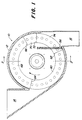
- a seed organ 10 for metering the seeds is at a standstill Provided housing 12 having an inlet 14 and an outlet 16.
- the housing 12 is open on one side and its outer surface or annular rim is designated by 18. From Fig. 2 it can still be seen that an annular shoulder 20 is incorporated into the inside of the outer surface 18.
- the side surface of the housing 12 is also equipped with a cam surface 22.
- a disc part 24 and at a distance from this a disc 26 are rotatably connected to a drive shaft 28. Disk part 24 and disk 26 can thus rotate together in the housing 12.
- the disc part 24 receives on a circular arc a plurality of selection fingers 30 or clamping fingers, the longitudinal axes of which are arranged parallel to the drive shaft 28.
- each selection finger 30 is guided in a guide tube 32 which in turn is connected to the disk part 24.
- the guide tube 32 can be formed in one piece or as shown in FIG. 3.
- the end of each selection finger 30 facing the cam surface 22 is designated 34 and the end facing the disk 26 is designated 36.
- the end 34 is hemispherical and lies in the area of the cam surface 22 against it.
- a spring 38 is provided which at one end rests against the side 40 of the disk part 24 facing the cam surface 22 and at the other end against a stop part 42 designed as a flange, which is connected to the selection finger 30.
- Each selection finger 30 is guided through the disk part 24, the side of which facing the disk 26 is designated 44, and extends in the direction of the disk part.
- the end 36 of the selection finger 30 which is assigned to this is designed as a gripping surface 46 which is formed by a conical bore 48. This creates an annular rim rim 50, which is used to take or grasp a single seed.
- the selection finger 30 can also be designed beveled at its end 36.
- the disc 26 is arranged parallel to the disc part 24 and provided on a circular arc with a plurality of seed cells 52 which are aligned with the selection fingers 30 and the number of which corresponds to the number of selection fingers 30.
- the seed cells 52 are also covered by membranes 54.
- An individual membrane can be assigned to each cell, or a single rotating membrane can be assigned to all cells.
- the circumferential membrane or the individual membranes are flexible and compliant so that they can adapt to the individual seed sizes. In this way, seeds of different sizes can be dosed, and changing the disc 26 when changing to other seeds is not absolutely necessary.
- the disk part 24 slides with its outer corner edge on the annular shoulder 20 of the housing 12 and the disk 26 slides with its outermost inside on the open side of the lateral surface 18 of the housing.
- Seed thus collects in the lower region of the housing 12 between the disk part 24 and the disk 26 in a crop receiving zone, as can be seen in FIG. 2.
- a sealing brush 56 is also provided between the disk part 24 and the disk 26. It prevents the direct passage of seeds from the crop receiving zone to the outlet 16 or into the crop dispensing zone and, because of their transversely arranged bristles, allows the selection fingers 30 to pass when they circulate from the exit zone into the entrance zone.
- the direction of rotation of the selection fingers 30 takes place with reference to FIG. 1 in the clockwise direction according to the direction of the arrow. From Fig. 1 it can also be seen that the sealing brush 56 is connected to the housing 12 or the jacket surface 18 and extends upwards seen from this.
- the cam surface 22 is provided with a rising ramp 60 which is formed between the lines 62 and 64. If now a selection finger 30 by the one located in the recording zone Seed passes, the ramp 60 will press the corresponding finger in the direction of the associated membrane-covered seed cell 52 against the action of the spring 38 until a single seed is held in the seed cell 52 by the finger 30. In the area between the lines 64 and 66 - the holding zone 68 - the cam surface 22 has a uniform thickness, and in this holding zone a single seed grain is held in each seed cell 52 by the associated finger 30. Line 66 is followed by a descending ramp 70, which at line 72 reaches the level of the side wall of housing 12.
- the fingers 30 are still pressed against the falling ramp 70 in this area, as a result of which they gradually move away from the seed cells and finally release the seed. This can then fall into the associated outlet 16 in the delivery zone 74, which lies between the lines 72 and 62 and in which the fingers 30 have been pulled away from the disk 26 via the springs 38.
- the selection fingers located in this area are thus pulled away from the associated seed cells. Seed slides between the fingers and the seed cells when the disc 26 and the disc part 26 are rotated through the receiving area. In this area, however, the fingers are gradually shifted towards the seed cells 52 by the rising ramp 60, so that they can finally hold a single seed in the associated seed cell.
- the membrane adapts to the respective seed size. A single seed is then held until the discharge zone is reached, where the seed is released again.
- the disk 26 rotating in the preferred embodiment can also be stationary.
- the selection fingers do not necessarily have to be controlled by a cam. They can also be guided in a setting that controls the back and forth movement of the fingers. Can on a spring be waived in such a case. On the other hand, it is also entirely possible and in some applications also appropriate that the fingers are moved towards the seed cells under spring action. The fingers then develop a stronger clamping effect. With such a design, the cam surface is then to be designed and arranged in such a way that it pulls or pushes the fingers away from the seed cells in the area of the sloping ramp or in the delivery area in order to be able to release the corresponding seed grain in this area.
Landscapes
- Life Sciences & Earth Sciences (AREA)
- Soil Sciences (AREA)
- Environmental Sciences (AREA)
- Sowing (AREA)
Applications Claiming Priority (2)
| Application Number | Priority Date | Filing Date | Title |
|---|---|---|---|
| US166753 | 1993-12-13 | ||
| US08/166,753 US5377867A (en) | 1993-12-13 | 1993-12-13 | Selector pin seed meter |
Publications (3)
| Publication Number | Publication Date |
|---|---|
| EP0657093A2 true EP0657093A2 (fr) | 1995-06-14 |
| EP0657093A3 EP0657093A3 (fr) | 1995-09-13 |
| EP0657093B1 EP0657093B1 (fr) | 1998-01-21 |
Family
ID=22604576
Family Applications (1)
| Application Number | Title | Priority Date | Filing Date |
|---|---|---|---|
| EP94118745A Expired - Lifetime EP0657093B1 (fr) | 1993-12-13 | 1994-11-29 | Elément de semoir |
Country Status (7)
| Country | Link |
|---|---|
| US (1) | US5377867A (fr) |
| EP (1) | EP0657093B1 (fr) |
| AU (1) | AU675599B2 (fr) |
| BR (1) | BR9404976A (fr) |
| CA (1) | CA2134501C (fr) |
| DE (1) | DE59405094D1 (fr) |
| ZA (1) | ZA949868B (fr) |
Families Citing this family (14)
| Publication number | Priority date | Publication date | Assignee | Title |
|---|---|---|---|---|
| IT1265571B1 (it) * | 1993-07-29 | 1996-11-22 | Matermacc Srl | Seminatrice pneumatica di precisione perfezionata |
| US6564730B2 (en) | 1995-12-29 | 2003-05-20 | Case Corporation | Seed planter apparatus and method |
| US6109193A (en) | 1995-12-29 | 2000-08-29 | Case Corporation | Seed planter apparatus and method |
| US6044779A (en) * | 1998-04-15 | 2000-04-04 | Case Corporation | Multiple drop seed disc |
| DE19901439C1 (de) * | 1999-01-15 | 2000-02-03 | Stocko Fasteners Gmbh | Sortiermagazin für die Bevorratung loser Kleinteile |
| US20050150442A1 (en) * | 2004-01-14 | 2005-07-14 | Enrique Friesen | Seed meter |
| US20060118573A1 (en) * | 2004-11-03 | 2006-06-08 | Ganz Brian L | Automated small item dispense module |
| US8850995B2 (en) | 2009-02-02 | 2014-10-07 | Deere & Company | Seeding machine with seed delivery system |
| US8850998B2 (en) | 2011-03-25 | 2014-10-07 | Deere & Company | Planting unit for a seeding machine having a seed meter and seed delivery system |
| CN102823362B (zh) * | 2012-09-13 | 2014-08-06 | 吉林大学 | 一种双斜面摇杆式排种器 |
| CN103329666B (zh) * | 2013-06-14 | 2015-07-08 | 华中农业大学 | 推杆搅盘组合双向气力式水稻芽种直播精量排种器 |
| WO2017088894A1 (fr) * | 2015-11-26 | 2017-06-01 | Harro Höfliger Verpackungsmaschinen GmbH | Dispositif et procédé d'éjection d'au moins une capsule d'un porte-capsule |
| CN105432193B (zh) * | 2016-01-07 | 2018-07-31 | 石河子大学 | 一种设有辅助夹种装置的排种器 |
| CN111436258B (zh) * | 2020-05-20 | 2022-07-12 | 范雪灵 | 一种农业用播种装置 |
Family Cites Families (17)
| Publication number | Priority date | Publication date | Assignee | Title |
|---|---|---|---|---|
| US1501335A (en) * | 1923-01-12 | 1924-07-15 | Josephine Aman | Potato planter |
| US3486659A (en) * | 1967-10-30 | 1969-12-30 | Massey Ferguson Inc | Shelled peanut planting apparatus |
| US3552601A (en) * | 1968-04-12 | 1971-01-05 | Deere & Co | Seed selecting mechanism |
| US3572548A (en) * | 1969-06-16 | 1971-03-30 | Bernard P Fuchs | Plateless seed planter |
| US3670671A (en) * | 1970-01-06 | 1972-06-20 | Int Harvester Co | Planter |
| DE2011462A1 (de) * | 1970-03-11 | 1971-09-23 | Gebr. Eberhardt, 7900 Ulm | Einzelkornsämaschine |
| US3717940A (en) * | 1971-05-03 | 1973-02-27 | Deering Milliken Res Corp | Coin machine |
| GB1450677A (en) * | 1972-09-13 | 1976-09-22 | Barker R J | Seed-dispensing device |
| GB1591794A (en) * | 1976-10-28 | 1981-06-24 | Rota Spoon Ltd | Seed dispensing device |
| AU524617B2 (en) * | 1979-01-16 | 1982-09-23 | Austin James Dobson | Single grain suction drum seeder |
| US4282985A (en) * | 1980-01-21 | 1981-08-11 | Ray Yamamoto | Seed plate |
| FR2513066A1 (fr) * | 1981-09-22 | 1983-03-25 | Feller Marc | Semoir de graines en poquets |
| US4609131A (en) * | 1984-06-11 | 1986-09-02 | Tieben James B | Seed dispensing device |
| US5027725A (en) * | 1989-04-13 | 1991-07-02 | Keeton Eugene G | Seed dispenser for planters |
| US4924786A (en) * | 1989-06-14 | 1990-05-15 | Keeton Eugene G | Seed dispenser with dual-faced seed plate |
| US5058766A (en) * | 1990-05-25 | 1991-10-22 | Kinze Manufacturing, Inc. | Seed meter for row crop planter unit |
| FR2663497B1 (fr) * | 1990-06-25 | 1994-02-25 | Jean Lagouarde | Selecteur de grain unique pour semoir en ligne. |
-
1993
- 1993-12-13 US US08/166,753 patent/US5377867A/en not_active Expired - Lifetime
-
1994
- 1994-10-27 CA CA002134501A patent/CA2134501C/fr not_active Expired - Fee Related
- 1994-11-29 DE DE59405094T patent/DE59405094D1/de not_active Expired - Fee Related
- 1994-11-29 EP EP94118745A patent/EP0657093B1/fr not_active Expired - Lifetime
- 1994-12-12 AU AU80374/94A patent/AU675599B2/en not_active Ceased
- 1994-12-12 ZA ZA949868A patent/ZA949868B/xx unknown
- 1994-12-13 BR BR9404976A patent/BR9404976A/pt not_active IP Right Cessation
Also Published As
| Publication number | Publication date |
|---|---|
| CA2134501A1 (fr) | 1995-06-14 |
| CA2134501C (fr) | 1997-10-07 |
| ZA949868B (en) | 1996-06-12 |
| AU675599B2 (en) | 1997-02-06 |
| US5377867A (en) | 1995-01-03 |
| EP0657093A3 (fr) | 1995-09-13 |
| AU8037494A (en) | 1995-06-22 |
| EP0657093B1 (fr) | 1998-01-21 |
| DE59405094D1 (de) | 1998-02-26 |
| BR9404976A (pt) | 1995-08-08 |
Similar Documents
| Publication | Publication Date | Title |
|---|---|---|
| EP0141249B1 (fr) | Semoir monograine | |
| DE68916976T2 (de) | Verteiler für eine Einzelkörnersämaschine. | |
| DE2217513C3 (de) | Verteilervorrichtung an Sämaschinen zum Ausgeben von einzelnen Körnern | |
| EP0657093B1 (fr) | Elément de semoir | |
| DE69414319T2 (de) | Einzelkornsämaschine | |
| DE2747866C2 (de) | Vorrichtung zum Ausstreuen von Saatgut | |
| EP0155688A2 (fr) | Semoir | |
| EP0195900B1 (fr) | Unité de semis pour semoirs monograines | |
| DE102013100118B3 (de) | Abstreifeinrichtung, Säherz und Einzelkornsämaschine | |
| WO2014184132A1 (fr) | Filtre pour matières en fusion avec dispositif d'entraînement pour disque de tamis rotatif | |
| DE3604628A1 (de) | Pneumatische einzelkornsaemaschine | |
| DE1582040A1 (de) | Praezisionssaemaschine | |
| DE102016203238A1 (de) | Befestigungsanordung einer Duplikatbeseitigungseinheit in einem Saatgutmessgerät | |
| DE3405361C1 (de) | Pnaumatische Einzelkornsaemaschine | |
| WO2017167957A1 (fr) | Dispositif de remplissage d'un contenant avec un matériau particulaire | |
| DE2200562C3 (de) | Legemaschine für Kartoffeln und dergleichen Feldfrüchte | |
| EP0106299A1 (fr) | Elément sélecteur pour semoir de précision pneumatique | |
| DE69405830T2 (de) | Verteilungskasten für eine mechanische Einzelkörnersämaschine | |
| EP3292747B1 (fr) | Semoir doté d'un dispositif de séparation individuelle de graines | |
| DE1582037C3 (de) | Einzelkornsämaschine | |
| EP1820382B1 (fr) | Semoir monograine pneumatique | |
| DE2644500B2 (de) | Vorrichtung zum Zuführen von Kartuschhülsen o.a. einendig geschlossenen, hohlen Werkstücken, in einer bestimmten Ausrichtung | |
| DE3120568C2 (de) | Einzelkornsägerät | |
| DE3000111C2 (de) | Einzelkornsämaschine | |
| EP1621059B1 (fr) | Semoir monograine pneumatique |
Legal Events
| Date | Code | Title | Description |
|---|---|---|---|
| PUAI | Public reference made under article 153(3) epc to a published international application that has entered the european phase |
Free format text: ORIGINAL CODE: 0009012 |
|
| AK | Designated contracting states |
Kind code of ref document: A2 Designated state(s): BE DE FR GB IT |
|
| PUAL | Search report despatched |
Free format text: ORIGINAL CODE: 0009013 |
|
| AK | Designated contracting states |
Kind code of ref document: A3 Designated state(s): BE DE FR GB IT |
|
| 17P | Request for examination filed |
Effective date: 19950928 |
|
| GRAG | Despatch of communication of intention to grant |
Free format text: ORIGINAL CODE: EPIDOS AGRA |
|
| GRAG | Despatch of communication of intention to grant |
Free format text: ORIGINAL CODE: EPIDOS AGRA |
|
| GRAH | Despatch of communication of intention to grant a patent |
Free format text: ORIGINAL CODE: EPIDOS IGRA |
|
| 17Q | First examination report despatched |
Effective date: 19970703 |
|
| GRAH | Despatch of communication of intention to grant a patent |
Free format text: ORIGINAL CODE: EPIDOS IGRA |
|
| GRAA | (expected) grant |
Free format text: ORIGINAL CODE: 0009210 |
|
| AK | Designated contracting states |
Kind code of ref document: B1 Designated state(s): BE DE FR GB IT |
|
| GBT | Gb: translation of ep patent filed (gb section 77(6)(a)/1977) |
Effective date: 19980126 |
|
| REF | Corresponds to: |
Ref document number: 59405094 Country of ref document: DE Date of ref document: 19980226 |
|
| ET | Fr: translation filed | ||
| ITF | It: translation for a ep patent filed | ||
| PLBE | No opposition filed within time limit |
Free format text: ORIGINAL CODE: 0009261 |
|
| STAA | Information on the status of an ep patent application or granted ep patent |
Free format text: STATUS: NO OPPOSITION FILED WITHIN TIME LIMIT |
|
| 26N | No opposition filed | ||
| PGFP | Annual fee paid to national office [announced via postgrant information from national office to epo] |
Ref country code: GB Payment date: 20011024 Year of fee payment: 8 |
|
| PGFP | Annual fee paid to national office [announced via postgrant information from national office to epo] |
Ref country code: BE Payment date: 20011121 Year of fee payment: 8 |
|
| REG | Reference to a national code |
Ref country code: GB Ref legal event code: IF02 |
|
| PG25 | Lapsed in a contracting state [announced via postgrant information from national office to epo] |
Ref country code: GB Free format text: LAPSE BECAUSE OF NON-PAYMENT OF DUE FEES Effective date: 20021129 |
|
| PG25 | Lapsed in a contracting state [announced via postgrant information from national office to epo] |
Ref country code: BE Free format text: LAPSE BECAUSE OF NON-PAYMENT OF DUE FEES Effective date: 20021130 |
|
| BERE | Be: lapsed |
Owner name: *DEERE & CY Effective date: 20021130 |
|
| GBPC | Gb: european patent ceased through non-payment of renewal fee | ||
| PG25 | Lapsed in a contracting state [announced via postgrant information from national office to epo] |
Ref country code: IT Free format text: LAPSE BECAUSE OF NON-PAYMENT OF DUE FEES;WARNING: LAPSES OF ITALIAN PATENTS WITH EFFECTIVE DATE BEFORE 2007 MAY HAVE OCCURRED AT ANY TIME BEFORE 2007. THE CORRECT EFFECTIVE DATE MAY BE DIFFERENT FROM THE ONE RECORDED. Effective date: 20051129 |
|
| PGFP | Annual fee paid to national office [announced via postgrant information from national office to epo] |
Ref country code: DE Payment date: 20081021 Year of fee payment: 15 |
|
| PGFP | Annual fee paid to national office [announced via postgrant information from national office to epo] |
Ref country code: FR Payment date: 20091201 Year of fee payment: 16 |
|
| PG25 | Lapsed in a contracting state [announced via postgrant information from national office to epo] |
Ref country code: DE Free format text: LAPSE BECAUSE OF NON-PAYMENT OF DUE FEES Effective date: 20100601 |
|
| REG | Reference to a national code |
Ref country code: FR Ref legal event code: ST Effective date: 20110801 |
|
| PG25 | Lapsed in a contracting state [announced via postgrant information from national office to epo] |
Ref country code: FR Free format text: LAPSE BECAUSE OF NON-PAYMENT OF DUE FEES Effective date: 20101130 |