EP0657095A1 - Moissonneuse batteuse équipée d'un hache-paille - Google Patents
Moissonneuse batteuse équipée d'un hache-paille Download PDFInfo
- Publication number
- EP0657095A1 EP0657095A1 EP94118261A EP94118261A EP0657095A1 EP 0657095 A1 EP0657095 A1 EP 0657095A1 EP 94118261 A EP94118261 A EP 94118261A EP 94118261 A EP94118261 A EP 94118261A EP 0657095 A1 EP0657095 A1 EP 0657095A1
- Authority
- EP
- European Patent Office
- Prior art keywords
- straw
- straw chopper
- chopper
- combine harvester
- harvester according
- Prior art date
- Legal status (The legal status is an assumption and is not a legal conclusion. Google has not performed a legal analysis and makes no representation as to the accuracy of the status listed.)
- Granted
Links
- 239000010902 straw Substances 0.000 title claims abstract description 129
- 230000008878 coupling Effects 0.000 claims abstract description 13
- 238000010168 coupling process Methods 0.000 claims abstract description 13
- 238000005859 coupling reaction Methods 0.000 claims abstract description 13
- 238000006073 displacement reaction Methods 0.000 claims abstract description 9
- 230000009286 beneficial effect Effects 0.000 description 1
- 230000001419 dependent effect Effects 0.000 description 1
- 238000011161 development Methods 0.000 description 1
- 230000018109 developmental process Effects 0.000 description 1
Images
Classifications
-
- A—HUMAN NECESSITIES
- A01—AGRICULTURE; FORESTRY; ANIMAL HUSBANDRY; HUNTING; TRAPPING; FISHING
- A01F—PROCESSING OF HARVESTED PRODUCE; HAY OR STRAW PRESSES; DEVICES FOR STORING AGRICULTURAL OR HORTICULTURAL PRODUCE
- A01F12/00—Parts or details of threshing apparatus
- A01F12/40—Arrangements of straw crushers or cutters
Definitions
- the invention relates to a combine harvester with a straw chopper connected downstream of a threshing and separating device, which can be displaced on the straw hood via a movement element into a working position and into a non-operating position.
- European patent application 0 224 803 discloses a combine harvester with a chopper mounted displaceably in the region of the outlet end of the straw hood by means of a toothed wheel and toothed rack, which is also displaceable in its two positions.
- DE-OS 38 26 066 shows a straw chopper pivotally mounted on the combine harvester, which can be pivoted by hand into the two positions using levers.
- the object of the invention is to move a straw chopper attached to the straw hood of the combine harvester in a simple and mechanical manner into its working position and its inoperative position, and inevitably and automatically the discharge nozzle of the straw chopper and / or to bring a straw screen to the operating and decommissioning position.
- the combine harvester is equipped with a straw chopper which is displaceably mounted on guides of the straw hood and which can be brought into its working position and its non-functional position by a pressure medium cylinder.
- the discharge chute of the straw chopper and / or the straw guide rake and / or a straw guide plate is simultaneously, inevitably and automatically brought into the operating and decommissioning position, with simple coupling elements being provided for this, which perform these movements as a function of one another.
- the straw chopper has been given an improved mode of operation and an increased utility value, since only one actuating member achieves multiple functions for the entire mode of operation of the straw chopper or its inoperative position.
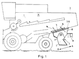
- the combine harvester (M) has a straw chopper (2) connected to a threshing and separating device (1), which can be moved to a working position (A) and a non-operating position (B) on the straw hood (3) via a movement element (4).
- the straw chopper (2) can be moved under the straw hood (3) by means of guides (5, 6) and can be moved into its two positions by means of the movement element (4), preferably a pressure medium cylinder.
- the discharge nozzle (7) of the straw chopper (2) and / or a straw guide rake (8) arranged on the straw chopper (2) is / are dependent on the displacement movement of the straw chopper (2) via coupling links (9 to 13) into a working position (A) and pivotable into a non-operating position (B).
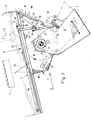
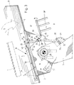
- the straw chopper (2) has a fixed straw baffle (14) and, depending on the displacement movement of the straw chopper (2) via the coupling members (9 to 13), into a straw inlet position (Fig. 2) and into a straw discharge position (Fig. 3 ) pivotable straw guide plate (15).
- the straw chopper (2) with its housing (18) receiving the cutting rotor (16) and counter knife (17), is slidably mounted under the straw hood (3) with profile rails (6), preferably U-rails.
- the pressure medium cylinder (4) designed as a double-acting push-pull cylinder, is mounted with its cylinder housing (4a) on the straw hood (3) and its piston rod (4b) acts indirectly on the rear end of the straw chopper housing (18).
- the piston rod (4b) of the pressure medium cylinder (4) is articulated on a control and driving part (9) which can be pivoted about a horizontal axis (19) on the straw chopper housing (18) and which controls the coupling members (10 to 13) and the displacement of the Straw chopper (2) causes.
- the control and pivoting part (9) is designed as a multi-armed lever and is pivotable about the axis (19) provided on the profile rail (6) of the straw chopper housing (18); On the one hand of the axis (19), the control and pivoting part (9) has a fork part (20) for articulating the piston rod (4b) of the pressure medium cylinder (4) in the horizontal axis (21) and on the other hand the axis (19) shows and control and pivoting part (9) with a stop (22) on the straw chopper housing (18) cooperating in two pivoting positions pivot limiting and driving fork (23).
- the control and pivoting part (9) has a lever-shaped extension (24) extending in the longitudinal direction of the pressure medium cylinder, to which a first lever (10) is articulated with one end in a horizontal pivot axis (25), the other end of which is connected via a horizontal axis (26) is articulated to a node plate (13) pivotably mounted on the straw chopper housing (18) about a stationary, horizontal axis (27).
- a second lever (11) is articulated with one end in a horizontal axis (28), the other end of which engages adjustably on the ejection nozzle (7).
- a third lever (12) is pivotally mounted on the node plate (13) in a horizontal axis (29) with one end, which has in its other end a shaft (30) rotatably mounted in the straw chopper housing (18), on which the straw screen (8 ) is fixed rigidly.
- the pivotable straw guide plate (15) is fastened to the pivotable node plate (13) and can be pivoted with it about the horizontal axis (27).
- the ejection nozzle (7) is pivotable about the rotor axis of rotation (31) and its lever (11) which moves it is articulated on an adjusting lever (32) which is attached to a perforated grid part (33) attached to the ejection nozzle (7) for the swivel angle size of the ejection nozzle (7) is set adjustable.
- the lever (11) is connected via a horizontal axis (34) to the adjusting lever (32), which in turn can be pivoted at one end in a horizontal axis (35) on the perforated grid part (33) and at the other end by a plug part (36 ), Locking part or the like.
- a plug part (36 ), Locking part or the like In the holes (33a) of the perforated grid part (33) can optionally be fixed and thus determines the swivel size of the ejection nozzle (7).
- the fixed axis (27) of the node plate (13) lies with the axes (26 to 29) of the three levers (10, 11, 12) on the corner points of a square, preferably a trapezoid.
- the straw guide rake (8) has a tube (37) with prongs (38) and this tube (37) is rotatably mounted at a limited angle about a rod (39) attached to the shaft (30).
- the tube (37) with tines (38) is attached to the straw chopper housing (18) by a control piece (40) and a stop (41) attached to the tube (37) when the straw screen (8) is swung up around the rod (39) to the center of the combine swung in.
- a straw screen (8) is arranged on each side of the straw chopper (2) and both straw screens (8) are attached to a common, continuous shaft (30) and can be swiveled towards each other by a stop (41) which interacts with a control piece (40) .
- the coupling members formed by the node plate (13), the three levers (10 to 12) and the control and pivoting part (9) are arranged on at least one side of the straw chopper (2) and can be actuated by the pressure medium cylinder (4).
- the straw (S) can now fall out of the outlet end of the straw hood (3) in the direction of arrow "C" and through the straw baffles (8) without being chopped onto the field.
- the chopper (2) has been moved into its working position, the straw chopper housing (18) on the guides (5, 6) being moved to below the outlet end of the straw hood (3) by extending the piston rod (4b) is.
- the tube (37) with prongs (38) and the rod (39) are rotated and the prongs (38) pivot inward in the direction of the arrow "I " a.
- the straw guide plate (15) rigidly connected to the node plate (13) is pivoted outwards (rear) and then forms an inlet funnel for the straw with the fixed straw guide plate (14) ( S) (see Fig. 2).
- the straw (S) then falls from the threshing and cutting device (1) in the direction of arrow "C" into the funnel formed by the guide plates (14, 15) and is in the Chopper (2) chopped and discharged from the chute (7).
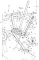
- Fig. 4 the movements of the coupling members (9 to 13) are illustrated by the arrows, and the straw guide rake (8) is swung up and in, Fig. 5 in the arrow "I” shows the pivoting of the tines (38).
- the tube (37) of the straw guide rake (8) has a groove (42) which extends in the pivoting direction and into which a pin (43) of the rod (39) engages; hereby the pivoting movement of the tube (37) with prongs (38) downwards and outwards into the functional position according to. Fig. 3 limited, in which the tube (37) with tines (38) automatically swings back by its own weight.
Landscapes
- Life Sciences & Earth Sciences (AREA)
- Environmental Sciences (AREA)
- Threshing Machine Elements (AREA)
- Harvester Elements (AREA)
Applications Claiming Priority (2)
| Application Number | Priority Date | Filing Date | Title |
|---|---|---|---|
| DE4341764A DE4341764C1 (de) | 1993-12-08 | 1993-12-08 | Mähdrescher mit Strohhäcksler |
| DE4341764 | 1993-12-08 |
Publications (2)
| Publication Number | Publication Date |
|---|---|
| EP0657095A1 true EP0657095A1 (fr) | 1995-06-14 |
| EP0657095B1 EP0657095B1 (fr) | 1998-08-26 |
Family
ID=6504434
Family Applications (1)
| Application Number | Title | Priority Date | Filing Date |
|---|---|---|---|
| EP94118261A Expired - Lifetime EP0657095B1 (fr) | 1993-12-08 | 1994-11-19 | Moissonneuse batteuse équipée d'un hache-paille |
Country Status (4)
| Country | Link |
|---|---|
| US (1) | US5501635A (fr) |
| EP (1) | EP0657095B1 (fr) |
| DE (1) | DE4341764C1 (fr) |
| DK (1) | DK0657095T3 (fr) |
Families Citing this family (23)
| Publication number | Priority date | Publication date | Assignee | Title |
|---|---|---|---|---|
| DE19535424A1 (de) * | 1995-09-23 | 1997-03-27 | Claas Ohg | Selbstfahrender Mähdrescher |
| DE19639755A1 (de) * | 1996-09-27 | 1998-04-02 | Claas Ohg | Vorrichtung zur Verhinderung des Verkantens von längsverschiebbar angeordneten Maschinenbaugruppen, insbesondere bei Anbauhäckslern von Mähdreschern |
| DE19822499A1 (de) * | 1998-05-19 | 1999-11-25 | Franz Schrattenecker | Spreuverteiler für einen Mähdrescher |
| DE19906454A1 (de) * | 1999-02-16 | 2000-08-31 | Deere & Co | Verteilvorrichtung einer Zerkleinerungsvorrichtung |
| DE19908111C1 (de) * | 1999-02-25 | 2000-07-27 | Claas Selbstfahr Erntemasch | Mähdrescher mit Breitverteileraustrag für gehäckseltes Stroh-Spreu-Gemisch |
| US6251009B1 (en) | 1999-08-06 | 2001-06-26 | Deere & Company | Straw chopper housing |
| DE10063550B4 (de) * | 2000-12-20 | 2008-10-02 | Deere & Company, Moline | Mähdrescher mit Häckseleinrichtung |
| DE10128052A1 (de) * | 2001-06-08 | 2002-12-12 | Deere & Co | Halterungszusammenbau einer Gutbearbeitungs und/oder Födereinrichtung |
| US6719627B2 (en) | 2001-12-17 | 2004-04-13 | Case Corporation | Multi-position linkage and locking mechanism for a crop residue spreader and/or chopper |
| US7083266B2 (en) * | 2002-10-30 | 2006-08-01 | Lexmark International, Inc. | Micro-miniature fluid jetting device |
| US6883299B1 (en) | 2003-08-05 | 2005-04-26 | Richard Gramm | Height sensor arrangement for agricultural applications |
| US7066810B2 (en) * | 2003-11-07 | 2006-06-27 | Cnh America Llc | System and method for positively discharging crop residue from a combine |
| DE102004014306A1 (de) | 2004-03-24 | 2005-10-27 | Deere & Company, Moline | Strohleitrechen |
| US7008315B2 (en) * | 2004-04-26 | 2006-03-07 | Redekop Chaff Systems Ltd. | Venting of a combine harvester |
| CA2473341A1 (fr) * | 2004-07-08 | 2006-01-08 | Highline Mfg. Inc. | Faconneuse de balles avec tete de coupe de fourrage |
| DE102006042970B4 (de) * | 2006-09-13 | 2014-07-03 | Deere & Company | Mähdrescher mit einem dem Strohhäcksler zugeordneten Schutzbügel und einem Strohleitrechen |
| US8876583B2 (en) * | 2009-12-02 | 2014-11-04 | Cnh Industrial America Llc | Regulator of residue flow for spreading devices on agricultural combines |
| BE1019956A3 (nl) | 2011-04-26 | 2013-03-05 | Cnh Belgium Nv | Hakmes met verhardende bekleding. |
| US10085378B2 (en) | 2015-10-09 | 2018-10-02 | Cnh Industrial America Llc | Agricultural chopper with movable pan |
| US10405498B2 (en) * | 2016-11-23 | 2019-09-10 | Cnh Industrial America Llc | Flail chopper assembly for an agricultural combine |
| BE1025193B1 (nl) * | 2017-05-04 | 2018-12-06 | Cnh Industrial Belgium Nv | Zelfblokkerend borgsysteem voor een kafschaal van een oogstmachine voor landbouwtoepassingen |
| US11019768B2 (en) * | 2018-02-26 | 2021-06-01 | Deere & Company | Double decker crop residue spreader |
| CN112042367A (zh) * | 2019-06-05 | 2020-12-08 | 丰疆智能科技股份有限公司 | 可翻转分流装置和其应用 |
Citations (7)
| Publication number | Priority date | Publication date | Assignee | Title |
|---|---|---|---|---|
| FR1073507A (fr) * | 1952-11-21 | 1954-09-27 | Dispositif pour hacher la paille et des matières similaires | |
| DE2047023A1 (de) * | 1970-09-24 | 1972-04-13 | Deere & Co | Verstellbare Anordnung eines an das Strohauslaufende von Dreschmaschinen oder Mähdreschern angebauten Häckslers |
| US3712309A (en) * | 1972-03-29 | 1973-01-23 | Allis Chalmers | Straw chopper mounting for combine |
| DE3119954A1 (de) * | 1981-05-20 | 1982-12-16 | Biso Bitter Gmbh & Co Kg, 4520 Melle | "maehdrescher" |
| GB2165732A (en) * | 1984-10-20 | 1986-04-23 | Claas Ohg | Combine harvester with supplementary straw chopper |
| EP0212269A1 (fr) * | 1985-08-08 | 1987-03-04 | BISO Bitter GmbH. & Co.KG. | Moissonneuse-batteuse équipée d'un hache-paille |
| DE3826066A1 (de) * | 1988-07-30 | 1990-02-01 | Deere & Co | Aufhaengung eines schwenkteils |
Family Cites Families (1)
| Publication number | Priority date | Publication date | Assignee | Title |
|---|---|---|---|---|
| US4669489A (en) * | 1985-12-02 | 1987-06-02 | Deere & Company | Straw chopper mounting for a combine |
-
1993
- 1993-12-08 DE DE4341764A patent/DE4341764C1/de not_active Expired - Fee Related
-
1994
- 1994-11-19 DK DK94118261T patent/DK0657095T3/da active
- 1994-11-19 EP EP94118261A patent/EP0657095B1/fr not_active Expired - Lifetime
- 1994-12-06 US US08/354,074 patent/US5501635A/en not_active Expired - Fee Related
Patent Citations (7)
| Publication number | Priority date | Publication date | Assignee | Title |
|---|---|---|---|---|
| FR1073507A (fr) * | 1952-11-21 | 1954-09-27 | Dispositif pour hacher la paille et des matières similaires | |
| DE2047023A1 (de) * | 1970-09-24 | 1972-04-13 | Deere & Co | Verstellbare Anordnung eines an das Strohauslaufende von Dreschmaschinen oder Mähdreschern angebauten Häckslers |
| US3712309A (en) * | 1972-03-29 | 1973-01-23 | Allis Chalmers | Straw chopper mounting for combine |
| DE3119954A1 (de) * | 1981-05-20 | 1982-12-16 | Biso Bitter Gmbh & Co Kg, 4520 Melle | "maehdrescher" |
| GB2165732A (en) * | 1984-10-20 | 1986-04-23 | Claas Ohg | Combine harvester with supplementary straw chopper |
| EP0212269A1 (fr) * | 1985-08-08 | 1987-03-04 | BISO Bitter GmbH. & Co.KG. | Moissonneuse-batteuse équipée d'un hache-paille |
| DE3826066A1 (de) * | 1988-07-30 | 1990-02-01 | Deere & Co | Aufhaengung eines schwenkteils |
Also Published As
| Publication number | Publication date |
|---|---|
| DK0657095T3 (da) | 1999-05-25 |
| EP0657095B1 (fr) | 1998-08-26 |
| DE4341764C1 (de) | 1995-01-19 |
| US5501635A (en) | 1996-03-26 |
Similar Documents
| Publication | Publication Date | Title |
|---|---|---|
| EP0657095B1 (fr) | Moissonneuse batteuse équipée d'un hache-paille | |
| DE3250062C2 (fr) | ||
| DE69207987T2 (de) | Heuwerbungsmaschine, insbesondere Schwader für geschnittenes Pflanzengut | |
| AT401596B (de) | Siebvorrichtung für einen mähdrescher, insbesondere für einen versuchsfeldmähdrescher | |
| DE19722793A1 (de) | Mähdrescher | |
| EP1408733B1 (fr) | Dispositif servant a ajuster la largeur d'ouverture du tamis de moissonneuses-batteuses | |
| DE19538199C2 (de) | Feldhäcksler mit Konditioniereinrichtung | |
| DE2836099B2 (de) | Mähdrescher mit am Ende eines Strohausfallschachtes angeordnetem Häcksler | |
| EP0832554B1 (fr) | Moissonneuse-batteuse | |
| EP1169907A1 (fr) | Dispositif inverseur pour machine agricole de récolte | |
| DE69705013T2 (de) | Heuwerbungsmaschine | |
| DE102020202976A1 (de) | Erntevorsatz mit Mulchgeräten zur Bearbeitung von auf einem Feld stehenden Pflanzenstümpfen mit verbessertem Schutz gegen abgeschleuderte Steine | |
| EP0492195A1 (fr) | Faucheuse-hacheuse | |
| EP3092890B1 (fr) | Barre de coupe de moissonneuse | |
| EP1110443B1 (fr) | Faucheuse-conditionneuse | |
| DE68906399T3 (de) | Vorrichtung zum mähen von gras oder ähnlichen pflanzen. | |
| DE3119954C2 (de) | Mähdrescher | |
| DE3546445A1 (de) | Vorrichtung zum vorschnitt von rebholz an weinstoecken in drahtrahmenanlagen mit kordonerziehung | |
| EP3804493A1 (fr) | Faucheuse dotée d'un dispositif de protection et engin de travaux doté d'une telle faucheuse | |
| DE69713966T2 (de) | Mäher mit Stütz- und Transporträdern | |
| DE10256541A1 (de) | Räumschild mit schwenkbarer Schürfleiste | |
| EP3400784B1 (fr) | Dispositif formant tamis pour une machine de récolte ainsi qu'une machine de récolte | |
| DE3224269A1 (de) | Auswurfkruemmer fuer landwirtschaftliche maschinen | |
| DE3835367A1 (de) | Vorrichtung fuer maehwerke | |
| EP4201188B1 (fr) | Appareil agricole |
Legal Events
| Date | Code | Title | Description |
|---|---|---|---|
| PUAI | Public reference made under article 153(3) epc to a published international application that has entered the european phase |
Free format text: ORIGINAL CODE: 0009012 |
|
| 17P | Request for examination filed |
Effective date: 19950325 |
|
| AK | Designated contracting states |
Kind code of ref document: A1 Designated state(s): BE DK FR GB |
|
| RAP1 | Party data changed (applicant data changed or rights of an application transferred) |
Owner name: CLAAS KOMMANDITGESELLSCHAFT AUF AKTIEN |
|
| 17Q | First examination report despatched |
Effective date: 19970219 |
|
| GRAG | Despatch of communication of intention to grant |
Free format text: ORIGINAL CODE: EPIDOS AGRA |
|
| GRAG | Despatch of communication of intention to grant |
Free format text: ORIGINAL CODE: EPIDOS AGRA |
|
| GRAH | Despatch of communication of intention to grant a patent |
Free format text: ORIGINAL CODE: EPIDOS IGRA |
|
| GRAH | Despatch of communication of intention to grant a patent |
Free format text: ORIGINAL CODE: EPIDOS IGRA |
|
| GRAA | (expected) grant |
Free format text: ORIGINAL CODE: 0009210 |
|
| AK | Designated contracting states |
Kind code of ref document: B1 Designated state(s): BE DK FR GB |
|
| ET | Fr: translation filed | ||
| GBT | Gb: translation of ep patent filed (gb section 77(6)(a)/1977) |
Effective date: 19980911 |
|
| REG | Reference to a national code |
Ref country code: DK Ref legal event code: T3 |
|
| PLBE | No opposition filed within time limit |
Free format text: ORIGINAL CODE: 0009261 |
|
| STAA | Information on the status of an ep patent application or granted ep patent |
Free format text: STATUS: NO OPPOSITION FILED WITHIN TIME LIMIT |
|
| 26N | No opposition filed | ||
| REG | Reference to a national code |
Ref country code: GB Ref legal event code: IF02 |
|
| PGFP | Annual fee paid to national office [announced via postgrant information from national office to epo] |
Ref country code: GB Payment date: 20101123 Year of fee payment: 17 |
|
| PGFP | Annual fee paid to national office [announced via postgrant information from national office to epo] |
Ref country code: DK Payment date: 20111124 Year of fee payment: 18 |
|
| GBPC | Gb: european patent ceased through non-payment of renewal fee |
Effective date: 20111119 |
|
| PG25 | Lapsed in a contracting state [announced via postgrant information from national office to epo] |
Ref country code: GB Free format text: LAPSE BECAUSE OF NON-PAYMENT OF DUE FEES Effective date: 20111119 |
|
| PGFP | Annual fee paid to national office [announced via postgrant information from national office to epo] |
Ref country code: BE Payment date: 20121129 Year of fee payment: 19 |
|
| PGFP | Annual fee paid to national office [announced via postgrant information from national office to epo] |
Ref country code: FR Payment date: 20121217 Year of fee payment: 19 |
|
| REG | Reference to a national code |
Ref country code: DK Ref legal event code: EBP |
|
| PG25 | Lapsed in a contracting state [announced via postgrant information from national office to epo] |
Ref country code: DK Free format text: LAPSE BECAUSE OF NON-PAYMENT OF DUE FEES Effective date: 20121130 |
|
| BERE | Be: lapsed |
Owner name: *CLAAS K.G.A.A. Effective date: 20131130 |
|
| REG | Reference to a national code |
Ref country code: FR Ref legal event code: ST Effective date: 20140731 |
|
| PG25 | Lapsed in a contracting state [announced via postgrant information from national office to epo] |
Ref country code: BE Free format text: LAPSE BECAUSE OF NON-PAYMENT OF DUE FEES Effective date: 20131130 |
|
| PG25 | Lapsed in a contracting state [announced via postgrant information from national office to epo] |
Ref country code: FR Free format text: LAPSE BECAUSE OF NON-PAYMENT OF DUE FEES Effective date: 20131202 |