EP0657128B1 - Meuble réfrigérant, notamment pour l'aménagement de magasins - Google Patents
Meuble réfrigérant, notamment pour l'aménagement de magasins Download PDFInfo
- Publication number
- EP0657128B1 EP0657128B1 EP94116292A EP94116292A EP0657128B1 EP 0657128 B1 EP0657128 B1 EP 0657128B1 EP 94116292 A EP94116292 A EP 94116292A EP 94116292 A EP94116292 A EP 94116292A EP 0657128 B1 EP0657128 B1 EP 0657128B1
- Authority
- EP
- European Patent Office
- Prior art keywords
- cooling device
- counter according
- levers
- cold
- cold counter
- Prior art date
- Legal status (The legal status is an assumption and is not a legal conclusion. Google has not performed a legal analysis and makes no representation as to the accuracy of the status listed.)
- Expired - Lifetime
Links
- 238000001816 cooling Methods 0.000 claims abstract description 82
- 239000006096 absorbing agent Substances 0.000 claims description 17
- 230000035939 shock Effects 0.000 claims description 17
- 230000006835 compression Effects 0.000 claims 1
- 238000007906 compression Methods 0.000 claims 1
- 238000010276 construction Methods 0.000 abstract 1
- 238000004140 cleaning Methods 0.000 description 12
- 239000002826 coolant Substances 0.000 description 4
- 238000009413 insulation Methods 0.000 description 3
- 238000013016 damping Methods 0.000 description 2
- 230000003670 easy-to-clean Effects 0.000 description 2
- 238000005057 refrigeration Methods 0.000 description 2
- 238000011109 contamination Methods 0.000 description 1
- 230000001419 dependent effect Effects 0.000 description 1
- 238000011161 development Methods 0.000 description 1
- 230000018109 developmental process Effects 0.000 description 1
- 230000000694 effects Effects 0.000 description 1
- 230000005484 gravity Effects 0.000 description 1
- NJPPVKZQTLUDBO-UHFFFAOYSA-N novaluron Chemical compound C1=C(Cl)C(OC(F)(F)C(OC(F)(F)F)F)=CC=C1NC(=O)NC(=O)C1=C(F)C=CC=C1F NJPPVKZQTLUDBO-UHFFFAOYSA-N 0.000 description 1
- 230000005855 radiation Effects 0.000 description 1
- 239000003507 refrigerant Substances 0.000 description 1
Images


Classifications
-
- A—HUMAN NECESSITIES
- A47—FURNITURE; DOMESTIC ARTICLES OR APPLIANCES; COFFEE MILLS; SPICE MILLS; SUCTION CLEANERS IN GENERAL
- A47F—SPECIAL FURNITURE, FITTINGS, OR ACCESSORIES FOR SHOPS, STOREHOUSES, BARS, RESTAURANTS OR THE LIKE; PAYING COUNTERS
- A47F3/00—Show cases or show cabinets
- A47F3/06—Show cases or show cabinets with movable or removable shelves or receptacles
-
- A—HUMAN NECESSITIES
- A47—FURNITURE; DOMESTIC ARTICLES OR APPLIANCES; COFFEE MILLS; SPICE MILLS; SUCTION CLEANERS IN GENERAL
- A47F—SPECIAL FURNITURE, FITTINGS, OR ACCESSORIES FOR SHOPS, STOREHOUSES, BARS, RESTAURANTS OR THE LIKE; PAYING COUNTERS
- A47F3/00—Show cases or show cabinets
- A47F3/04—Show cases or show cabinets air-conditioned, refrigerated
- A47F3/0482—Details common to both closed and open types
- A47F3/0486—Details common to both closed and open types for charging, displaying or discharging the articles
Definitions
- the invention relates to a particular one intended for shopfitting Refrigerator, which essentially consists of a cooling table, which on a pedestal is a table top for placing the ones to be presented to the customer Goods and which also has a cooling device, at least the perishable goods lying on the table top to be able to keep fresh.
- AT-B-394 487 from which the present invention is based discloses one Refrigerated furniture for shopfitting with one on a table top of a cooling table arranged coolable shelf, which has a heat exchanger in the form of a Cooling evaporator of a cooling unit can be cooled.
- a blower and a disk-shaped cover are provided to the Area of the presented goods to be cooled from the access area for the Detach customers.
- the cooling device of the refrigerated cabinet described is can still be swiveled up around a rear horizontal axis and by means of a Support arms can be supported in the up position.
- the invention has for its object a refrigerator, in particular is intended for shopfitting to create that, on the one hand, easy to maintain or is easy to clean and on the other hand not a special one Insulation is required to achieve the desired cooling performance.
- the invention makes it possible to use the refrigerator after use surfaces to be cleaned such as the top of the Table top, but also the control system for the cooling air, simple and easy to clean, because the appropriate surfaces for a convenient cleaning can be made easily accessible when the Cooling device and any associated parts from the Operating position in a retracted and raised rest position has moved.
- the cooling device containing an evaporator for the inside the cooling air to be circulated has a closed channel, through which the cooling air flows in a targeted and inevitable manner insulation of the evaporator against heat radiation not necessary on the outside, because most of the performance of the evaporator is discharged through the air flowing through it.
- the cooling device that can be retracted from the operating position and raised to be able to set down in the lowered operating position and thus an impact on the base, which is preferably trough-shaped is designed to prevent, according to the invention in the movable Lever adjusting device at least one shock absorber installed, which is preferably between one of the levers and the trough-shaped Pad is articulated and thus adjustable.
- the articulation point on one lever can be appropriately adjusted or adjust to optimally use the damping force of the shock absorbers and to be able to adjust the weight of the respective cooling device.
- the cooling device is included the lever linkage and the trough-shaped base as a module-shaped Trained unit, which is installed as a whole in a refrigerator and can also be removed from the refrigerator. This includes, for example just tighten or loosen four fastening screws.
- the cooling device can therefore also be used after the period of use reuse the refrigerator by placing it in a new refrigerator like installing a new sales counter. This is particularly useful because the life of the cooler is often much longer than that The refrigerator is in use.
- cooling devices can also be fitted to such Place a sales counter later, where originally no cooling was desired or provided.
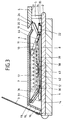
- the cooling table (1) intended for shopfitting has a fixed one Table top (2), from the front end of a transparent cover (3) runs upwards while on the rear end a worktop (4) is supported by a raised wall (5).
- a cooling device (6) arranged with circulating and works with cooled circulating air.
- the cooling device (6) has a box-shaped housing (7) which in the Operating position, as shown in Fig. 1, attached to the table top (2) Tub (8) covered.
- the box-shaped housing (7) is by means of angle levers (9) and straight Lever (10) on the table top (2) and / or the tub (8) in this way stored that it from the operating position shown in Fig. 1 in move and lift the cleaning position shown in Fig. 2 can be, and vice versa.
- the angle levers (9) and the straight-line levers (10) are shown in FIG. 1 and 2 only one to recognize each because the other same levers lie in flight with one another and thus overlap each other in the drawing.
- a channel (11) which contains an evaporator (12) which can be flowed through by the circulating air to be cooled when the Cooling device (6) is in the operating position shown in Fig. 1.
- an evaporator (12) which can be flowed through by the circulating air to be cooled when the Cooling device (6) is in the operating position shown in Fig. 1.
- a disc-like axial fan (14) let in through openings in an end wall (15) of the housing (7) (16) Air from the space between the cover plate (3) and the housing (7) sucks and through the channel (11) and thus accommodated therein Evaporator (12) conducts.
- This air is cooled in the evaporator (12), by means of a cooling medium passed through a cooling coil (17), by a pipe (18) serving as an inlet shown coolant source and by another, in pipe, not recognizable in the drawing, is returned to the coolant source becomes.
- outlet opening (20) is located under the wedge-shaped front edge (21) of the worktop (4) so that the cooled leaving the channel (11) Air is redirected and into the space above the cooling device, so to speak (6) is directed, that is, to where the goods to be cooled when operating the cooling table.
- the adjusting screw (23) is set so that the trough-shaped Flap (22) in the operating position with one on the outer or free End of the same flange (26) against the underside (27) of the Worktop (4) creates a seal, so to speak, so that the out of the channel (11) Do not let the cooled air flow out downwards or backwards can, but between the worktop (4) or the front edge (21) and the end wall (19) of the housing (7) upwards and thus towards deflected backwards according to the inclined position of the end wall (19) and is led.
- the cooling device (6) supported on two different lever arms, namely at the end facing the cover plate (3) of the cooling table (1) by means of Angle levers (9) and at the opposite end using straight-line levers (10), the latter between their two articulation points (28 and 29) a larger actual length than the angle lever (9) between them Have articulation points (30 and 31). Therefore, the rear end of the The cooling device (6) is raised more when it is lifted off the table top (2) as its front end, as shown in FIG. 2.
- the cooling device (6) lay the angle lever (9) with their shorter leg (32) on the top (34) of the table top (2) or the bottom of the tub (8) attached to the table top, so that the Cooling device stable in the raised and retracted position is held, also because the upper articulation point (31) the angle lever (9) now on the other side of the lower pivot point (30) as in the operating position (Fig. 1). Thereby there is a so-called dead center lock.
- Fig. 2 it can be seen that after lifting the cooling device (6) the top (4) of the table top (2) and the inside of the tub (8) are easily accessible for cleaning purposes. Even the one hanging down freely Flap (22), in the operating position through the outlet opening (20) of the channel (11) goods, remnants of goods or other dirt fall can be easily accessed for cleaning purposes. Even the inside the rear end of the channel (11) is free for cleaning purposes, so that if contamination should actually occur there, this can be removed without difficulty.
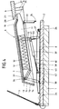
- 3 and 4 differs from the embodiment 1 and 2 essentially in that the housing (7) of the cooling device (6) not only at the rear end on a straight line Lever (10) is supported, but also at the front end on a straight line Levers (36), which are shorter than the levers (10) are.
- the above is in connection with 1 and 2 described dead center lock the housing (7) in the retracted and raised position, since the upper pivot point (31) of the shorter straight line Lever (36) goes over the lower pivot point (30) when the housing (7) of the cooling device (6) from the lowered one shown in FIG. 3 Operating position in the retracted and raised shown in Fig. 4 Cleaning position is moved.
- This shock absorber (38) is in the embodiment shown a cylindrical air spring with a Cylinder housing (39) and one protruding from the cylinder housing and extendable piston rod (40).
- the cylinder housing (39) is with an attached head piece (41) articulated with the relevant Lever (10) connected while at the outer end of the piston rod (40) further head piece (42) is attached, which is articulated with the relevant Side wall (37) of the tub (8) is connected.
- a helical spring is freely displaceable on the piston rod (40) (43) which, when the housing (7) of the cooling device in the lowered Operating position (Fig. 3) is from the cylinder housing (39) of the shock absorber (38) against that attached to the piston rod (40) Headpiece (42) is pressed while being preloaded.
- the longer lever (10) contains a number of arranged in series Holes (44) into which the head piece (41) of the shock absorber in question (38) can optionally be hooked to the effective lever arm of the shock absorber according to the respective operating conditions or to be able to change.
- the shock absorbers (38) serve to retract and lift the housing (7) to facilitate the cooling device (6) and on the other hand the Steam back moving the cooling device (6) into the operating position.
- the coil spring (43) supports this damping effect.
- shock absorber (38) is preferably designed as an air spring a different type of shock absorber is also conceivable, for example a hydraulic shock absorber.
- shock absorber (38) It may be sufficient to have only one on one side of the cooling device (6) Install shock absorber (38). For the sake of symmetry and by one To counteract tilting of the adjusting mechanism, it is advisable Shock absorbers (38) must be provided on both sides of the cooling device (6).
- the tub (8) with the cooling device arranged thereon (6) and the adjustment mechanism designed as a modular unit be in a refrigeration cabinet such as a sales counter - also retrospectively - installed and removed from this again can be made without major changes to the refrigerator itself to have to. Rather, it is sufficient to use the tub with the help of not shown Screws which are screwed into the table top (2) or can be inserted through this table top, on the table top to be detachably attached.
Landscapes
- Physics & Mathematics (AREA)
- Thermal Sciences (AREA)
- Devices That Are Associated With Refrigeration Equipment (AREA)
- Table Equipment (AREA)
Claims (15)
- Meuble réfrigérant, notamment pour l'aménagement de magasins, comprenant une table réfrigérante (1) constituant un socle, un dispositif de refroidissement (6) disposé sur le dessus (2) de la table réfrigérante, dispositif qui présente un évaporateur (12) ainsi qu'une soufflante (14) refoulant de l'air de refroidissement à travers l'évaporateur, et comprenant un capot (3) en forme de vitre, caractérisé en ce que le dispositif de refroidissement (6) est réalisé sous la forme d'une unité compacte et est monté sur le dessus de table en pouvant être reculé à partir de sa position de service et relevé à l'écart du dessus de table (2).
- Meuble réfrigérant selon la revendication 1, caractérisé en ce qu'un plateau de travail (4), qui s'appuie sur le dessus de table (2) dans la position de service du dispositif de refroidissement, est fixé sur le dispositif de refroidissement (6).
- Meuble réfrigérant selon la revendication 1 ou 2, caractérisé en ce que le dispositif de refroidissement (6) présente un boítier (7) en forme de caisson, conçu à la manière d'un capot, qui comprend un conduit (11) dans lequel est incorporé un évaporateur (12), auquel est associé au moins une soufflante (14) pour faire circuler l'air de refroidissement.
- Meuble réfrigérant selon l'une quelconque des revendications 1 à 3, caractérisé en ce qu'un élément déflecteur (22), pour dévier l'air de refroidissement refoulé à travers le conduit (11) du dispositif de refroidissement, est prévu à l'extrémité de sortie (19, 20) du dispositif de refroidissement (6).
- Meuble réfrigérant selon la revendication 4, caractérisé en ce que l'élément déflecteur (22) est un volet qui est monté à pivotement autour d'un axe horízontal et qui, dans la position de service du dispositif de refroidissement (6), s'applique hermétiquement, par une extrémité (26), contre le dessous (27) du plateau de travail (4).
- Meuble réfrigérant selon la revendication 5, caractérisé en ce qu'au moins une vis de réglage (23), servant d'appui pour le volet, est prévue pour le réglage du volet (22) dans la position de service.
- Meuble réfrigérant selon l'une quelconque des revendications 1 à 6, caractérisé en ce que le dispositif de refroidissement (6) est soutenu à pivotement sur des leviers (9, 10 ; 36).
- Meuble réfrigérant selon la revendication 7, caractérisé en ce que les leviers (10) qui soutiennent l'extrémité arrière du dispositif de refroidissement (6) sont plus longs que les leviers (9 ; 36) qui soutiennent l'extrémité avant.
- Meuble réfrigérant selon la revendication 7 ou 8, caractérisé en ce que les leviers qui soutiennent l'extrémité avant du dispositif de refroidissement (6) sont réalisés sous la forme de leviers coudés (9) ou de leviers rectilignes (36), qui passent par un point mort lors du déplacement du dispositif de refroidissement.
- Meuble réfrigérant selon l'une quelconque des revendications 1 à 9, caractérisé en ce qu'un amortisseur à ressort (38) est articulé sur au moins un des leviers (9, 10 ; 36).
- Meuble réfrigérant selon la revendication 10, caractérisé en ce que l'amortisseur (38) est un ressort pneumatique en forme de cylindre.
- Meuble réfrigérant selon la revendication 11, caractérisé en ce qu'un ressort de pression (43) est disposé sur l'extrémité libre de la tige de piston (40) du ressort pneumatique (38), ressort contre lequel s'applique sous pression, dans la position abaissée du dispositif de refroidissement (6), le boítier cylindrique (39) du ressort pneumatique (38).
- Meuble réfrigérant selon l'une quelconque des revendications 1 à 12, caractérisé en ce que le dispositif de refroidissement (6) est réalisé, conjointement avec un support (8) disposé en dessous de lui ainsi qu'avec les leviers (9, 10 ; 36) soutenant le dispositif de refroidissement sur le support, sous la forme d'une unité modulaire pouvant être montée et démontée.
- Meuble réfrigérant selon la revendication 13, caractérisé en ce que les amortisseurs (38) sont articulés par une extrémité sur le support (8) en forme de cuvette, et par l'autre extrémité respectivement sur un des leviers plus longs (10).
- Meuble réfrigérant selon la revendication 14, caractérisé en ce que les leviers plus longs (10) comportent un certain nombre de trous (44) permettant de choisir le point d'articulation des amortisseurs (38).
Applications Claiming Priority (4)
| Application Number | Priority Date | Filing Date | Title |
|---|---|---|---|
| DE9318953U DE9318953U1 (de) | 1993-12-10 | 1993-12-10 | Kühlmöbel, insbesondere für den Ladenbau |
| DE9318953U | 1993-12-10 | ||
| DE9409985U DE9409985U1 (de) | 1993-12-10 | 1994-06-21 | Kühlmöbel, insbesondere für den Ladenbau |
| DE9409985U | 1994-06-21 |
Publications (2)
| Publication Number | Publication Date |
|---|---|
| EP0657128A1 EP0657128A1 (fr) | 1995-06-14 |
| EP0657128B1 true EP0657128B1 (fr) | 1998-09-23 |
Family
ID=25961507
Family Applications (1)
| Application Number | Title | Priority Date | Filing Date |
|---|---|---|---|
| EP94116292A Expired - Lifetime EP0657128B1 (fr) | 1993-12-10 | 1994-10-15 | Meuble réfrigérant, notamment pour l'aménagement de magasins |
Country Status (2)
| Country | Link |
|---|---|
| EP (1) | EP0657128B1 (fr) |
| AT (1) | ATE171349T1 (fr) |
Families Citing this family (3)
| Publication number | Priority date | Publication date | Assignee | Title |
|---|---|---|---|---|
| DE19639108C1 (de) * | 1996-09-24 | 1998-01-22 | Hertel Guenther | Ladentheke, insbesondere Kühltheke |
| CN105486011B (zh) * | 2015-12-24 | 2018-05-11 | 合肥华凌股份有限公司 | 冰箱玻璃顶盖及冰箱 |
| BE1029187B1 (nl) * | 2021-03-10 | 2022-10-10 | Integral Nv | Koeltoonbank voorzien van een hefsysteem |
Family Cites Families (4)
| Publication number | Priority date | Publication date | Assignee | Title |
|---|---|---|---|---|
| DE3613185A1 (de) * | 1986-04-18 | 1987-10-22 | Ladenbau Maier | Kuehltheke |
| AT394487B (de) * | 1988-11-30 | 1992-04-10 | Hauser Erwin Dr | Kuehlvitrine |
| DE8815905U1 (de) * | 1988-12-22 | 1989-02-09 | Wescho-Ladenbau GmbH & Co KG, 5800 Hagen | Verkaufstheke |
| DE9113819U1 (de) * | 1991-11-06 | 1992-02-27 | Aichinger GmbH & Co. Einrichtungsbau Aluminium-Fenster- und -Fassaden KG, 8500 Nürnberg | Verkaufstheke, insbesondere Kühltheke |
-
1994
- 1994-10-15 AT AT94116292T patent/ATE171349T1/de not_active IP Right Cessation
- 1994-10-15 EP EP94116292A patent/EP0657128B1/fr not_active Expired - Lifetime
Also Published As
| Publication number | Publication date |
|---|---|
| EP0657128A1 (fr) | 1995-06-14 |
| ATE171349T1 (de) | 1998-10-15 |
Similar Documents
| Publication | Publication Date | Title |
|---|---|---|
| EP1155263B1 (fr) | Dispositif d'aspiration d'emanations installe dans une zone proche des zones de cuisson a decouvert | |
| DE1431673A1 (de) | Vorrichtung zum Entleeren eines Schuettgut erhaltenden Kippbehaelters | |
| DE69701289T2 (de) | Schleuse für kugeln zur reinigung von kühlsystemen | |
| DE10304012A1 (de) | Klimaschrank | |
| DE19825323A1 (de) | Backofen mit einem Laufwagen für ein Halterungsteil für Gargutträger | |
| EP0657128B1 (fr) | Meuble réfrigérant, notamment pour l'aménagement de magasins | |
| AT509937B1 (de) | Kühltheke | |
| DE9409985U1 (de) | Kühlmöbel, insbesondere für den Ladenbau | |
| DE3613185A1 (de) | Kuehltheke | |
| DE10250574A1 (de) | Luftrücklauf-Luftleitwand mit Filter | |
| CH636510A5 (en) | Sales and/or display cabinet with a refrigerated merchandise compartment | |
| EP0830827B1 (fr) | Comptoir de magasin, en particulier comptoir frigorifique | |
| DE2942491A1 (de) | Kuehltruhe | |
| DE102011084912A1 (de) | Umlufteinheit mit Umluftfilterelement für Dunstabzugshaube | |
| DE2646380C2 (de) | Einrichtung zum Unterbringen einer Auswahl von Nahrungsmitteln mit einer Kühlstation und einer in diese einfahrbaren Trageinheit | |
| DE102021104775B4 (de) | Anordnung zum Abklappen und Einfahren oder Einschieben der Frontscheibe einer Theke | |
| DE10348246B3 (de) | Kühlvorrichtung mit klappbarer Warenauflage | |
| DE19548377C2 (de) | Kühltheke | |
| DE102011106208A1 (de) | Kühltheke | |
| EP2512296A2 (fr) | Comptoir à marchandises | |
| EP1922958B1 (fr) | Ensemble constitué d'un meuble de présentation et un dispositif réfrigérant | |
| DE3843247C1 (en) | Display counter | |
| DE8610690U1 (de) | Kühltheke | |
| DE102014017122B3 (de) | Kühlvorrichtung mit verstellbarem Luftausblasbereich | |
| DE102010022860A1 (de) | Kühltheke |
Legal Events
| Date | Code | Title | Description |
|---|---|---|---|
| PUAI | Public reference made under article 153(3) epc to a published international application that has entered the european phase |
Free format text: ORIGINAL CODE: 0009012 |
|
| AK | Designated contracting states |
Kind code of ref document: A1 Designated state(s): AT BE CH DE DK ES FR GB GR IE IT LI LU MC NL PT SE |
|
| RAX | Requested extension states of the european patent have changed |
Free format text: SI PAYMENT 941108 |
|
| 17P | Request for examination filed |
Effective date: 19951115 |
|
| 17Q | First examination report despatched |
Effective date: 19970211 |
|
| GRAG | Despatch of communication of intention to grant |
Free format text: ORIGINAL CODE: EPIDOS AGRA |
|
| GRAG | Despatch of communication of intention to grant |
Free format text: ORIGINAL CODE: EPIDOS AGRA |
|
| GRAH | Despatch of communication of intention to grant a patent |
Free format text: ORIGINAL CODE: EPIDOS IGRA |
|
| GRAH | Despatch of communication of intention to grant a patent |
Free format text: ORIGINAL CODE: EPIDOS IGRA |
|
| GRAA | (expected) grant |
Free format text: ORIGINAL CODE: 0009210 |
|
| AK | Designated contracting states |
Kind code of ref document: B1 Designated state(s): AT BE CH DE DK ES FR GB GR IE IT LI LU MC NL PT SE |
|
| AX | Request for extension of the european patent |
Free format text: SI PAYMENT 941108 |
|
| PG25 | Lapsed in a contracting state [announced via postgrant information from national office to epo] |
Ref country code: NL Free format text: LAPSE BECAUSE OF FAILURE TO SUBMIT A TRANSLATION OF THE DESCRIPTION OR TO PAY THE FEE WITHIN THE PRESCRIBED TIME-LIMIT Effective date: 19980923 Ref country code: IT Free format text: LAPSE BECAUSE OF FAILURE TO SUBMIT A TRANSLATION OF THE DESCRIPTION OR TO PAY THE FEE WITHIN THE PRE;WARNING: LAPSES OF ITALIAN PATENTS WITH EFFECTIVE DATE BEFORE 2007 MAY HAVE OCCURRED AT ANY TIME BEFORE 2007. THE CORRECT EFFECTIVE DATE MAY BE DIFFERENT FROM THE ONE RECORDED.SCRIBED TIME-LIMIT Effective date: 19980923 Ref country code: GR Free format text: LAPSE BECAUSE OF FAILURE TO SUBMIT A TRANSLATION OF THE DESCRIPTION OR TO PAY THE FEE WITHIN THE PRESCRIBED TIME-LIMIT Effective date: 19980923 Ref country code: ES Free format text: THE PATENT HAS BEEN ANNULLED BY A DECISION OF A NATIONAL AUTHORITY Effective date: 19980923 |
|
| REF | Corresponds to: |
Ref document number: 171349 Country of ref document: AT Date of ref document: 19981015 Kind code of ref document: T |
|
| REG | Reference to a national code |
Ref country code: CH Ref legal event code: NV Representative=s name: DIETLIN & CIE S.A. Ref country code: CH Ref legal event code: EP |
|
| PG25 | Lapsed in a contracting state [announced via postgrant information from national office to epo] |
Ref country code: LU Free format text: LAPSE BECAUSE OF NON-PAYMENT OF DUE FEES Effective date: 19981015 Ref country code: AT Free format text: LAPSE BECAUSE OF NON-PAYMENT OF DUE FEES Effective date: 19981015 |
|
| PG25 | Lapsed in a contracting state [announced via postgrant information from national office to epo] |
Ref country code: SE Free format text: LAPSE BECAUSE OF NON-PAYMENT OF DUE FEES Effective date: 19981016 |
|
| PGFP | Annual fee paid to national office [announced via postgrant information from national office to epo] |
Ref country code: BE Payment date: 19981020 Year of fee payment: 5 |
|
| REF | Corresponds to: |
Ref document number: 59406966 Country of ref document: DE Date of ref document: 19981029 |
|
| PG25 | Lapsed in a contracting state [announced via postgrant information from national office to epo] |
Ref country code: LI Free format text: LAPSE BECAUSE OF NON-PAYMENT OF DUE FEES Effective date: 19981031 Ref country code: CH Free format text: LAPSE BECAUSE OF NON-PAYMENT OF DUE FEES Effective date: 19981031 |
|
| GBT | Gb: translation of ep patent filed (gb section 77(6)(a)/1977) |
Effective date: 19981008 |
|
| PG25 | Lapsed in a contracting state [announced via postgrant information from national office to epo] |
Ref country code: IE Free format text: LAPSE BECAUSE OF NON-PAYMENT OF DUE FEES Effective date: 19981123 |
|
| ET | Fr: translation filed | ||
| REG | Reference to a national code |
Ref country code: IE Ref legal event code: FG4D Free format text: GERMAN |
|
| PG25 | Lapsed in a contracting state [announced via postgrant information from national office to epo] |
Ref country code: GB Free format text: LAPSE BECAUSE OF NON-PAYMENT OF DUE FEES Effective date: 19981223 Ref country code: DK Free format text: LAPSE BECAUSE OF FAILURE TO SUBMIT A TRANSLATION OF THE DESCRIPTION OR TO PAY THE FEE WITHIN THE PRESCRIBED TIME-LIMIT Effective date: 19981223 |
|
| REG | Reference to a national code |
Ref country code: PT Ref legal event code: SC4A Free format text: AVAILABILITY OF NATIONAL TRANSLATION Effective date: 19980925 |
|
| NLV1 | Nl: lapsed or annulled due to failure to fulfill the requirements of art. 29p and 29m of the patents act | ||
| PG25 | Lapsed in a contracting state [announced via postgrant information from national office to epo] |
Ref country code: MC Free format text: LAPSE BECAUSE OF NON-PAYMENT OF DUE FEES Effective date: 19990430 |
|
| REG | Reference to a national code |
Ref country code: CH Ref legal event code: PL |
|
| PLBE | No opposition filed within time limit |
Free format text: ORIGINAL CODE: 0009261 |
|
| STAA | Information on the status of an ep patent application or granted ep patent |
Free format text: STATUS: NO OPPOSITION FILED WITHIN TIME LIMIT |
|
| EUG | Se: european patent has lapsed |
Ref document number: 94116292.7 |
|
| PG25 | Lapsed in a contracting state [announced via postgrant information from national office to epo] |
Ref country code: DE Free format text: LAPSE BECAUSE OF NON-PAYMENT OF DUE FEES Effective date: 19990803 |
|
| GBPC | Gb: european patent ceased through non-payment of renewal fee |
Effective date: 19981223 |
|
| REG | Reference to a national code |
Ref country code: IE Ref legal event code: MM4A |
|
| PG25 | Lapsed in a contracting state [announced via postgrant information from national office to epo] |
Ref country code: FR Free format text: LAPSE BECAUSE OF NON-PAYMENT OF DUE FEES Effective date: 19990831 |
|
| 26N | No opposition filed | ||
| REG | Reference to a national code |
Ref country code: FR Ref legal event code: ST |
|
| PG25 | Lapsed in a contracting state [announced via postgrant information from national office to epo] |
Ref country code: BE Free format text: LAPSE BECAUSE OF NON-PAYMENT OF DUE FEES Effective date: 19991031 |
|
| BERE | Be: lapsed |
Owner name: SIMONS HENRI Effective date: 19991031 |
|
| PG25 | Lapsed in a contracting state [announced via postgrant information from national office to epo] |
Ref country code: PT Free format text: LAPSE BECAUSE OF NON-PAYMENT OF DUE FEES Effective date: 20000430 |
|
| REG | Reference to a national code |
Ref country code: PT Ref legal event code: MM4A Free format text: LAPSE DUE TO NON-PAYMENT OF FEES Effective date: 20000430 |
|
| PG25 | Lapsed in a contracting state [announced via postgrant information from national office to epo] |
Ref country code: PT Free format text: LAPSE BECAUSE OF NON-PAYMENT OF DUE FEES Effective date: 19981015 |
|
| PG25 | Lapsed in a contracting state [announced via postgrant information from national office to epo] |
Ref country code: FR Free format text: LAPSE BECAUSE OF NON-PAYMENT OF DUE FEES Effective date: 19981031 |