EP0657196B1 - Perfectionnements apportés aux décanteurs - Google Patents
Perfectionnements apportés aux décanteurs Download PDFInfo
- Publication number
- EP0657196B1 EP0657196B1 EP94402640A EP94402640A EP0657196B1 EP 0657196 B1 EP0657196 B1 EP 0657196B1 EP 94402640 A EP94402640 A EP 94402640A EP 94402640 A EP94402640 A EP 94402640A EP 0657196 B1 EP0657196 B1 EP 0657196B1
- Authority
- EP
- European Patent Office
- Prior art keywords
- liquid
- openings
- settling tank
- row
- floor
- Prior art date
- Legal status (The legal status is an assumption and is not a legal conclusion. Google has not performed a legal analysis and makes no representation as to the accuracy of the status listed.)
- Expired - Lifetime
Links
- 230000006872 improvement Effects 0.000 title description 3
- 239000007788 liquid Substances 0.000 claims abstract description 39
- 238000005192 partition Methods 0.000 claims abstract description 3
- 239000012530 fluid Substances 0.000 claims description 13
- 239000000463 material Substances 0.000 claims description 9
- 238000009434 installation Methods 0.000 claims description 4
- 238000011161 development Methods 0.000 claims description 3
- 230000021715 photosynthesis, light harvesting Effects 0.000 claims description 3
- 230000003094 perturbing effect Effects 0.000 claims 1
- 230000001105 regulatory effect Effects 0.000 claims 1
- 238000005352 clarification Methods 0.000 abstract 1
- 238000010908 decantation Methods 0.000 description 4
- 235000021183 entrée Nutrition 0.000 description 4
- 230000000694 effects Effects 0.000 description 3
- 230000009467 reduction Effects 0.000 description 3
- 241001080024 Telles Species 0.000 description 2
- 230000009471 action Effects 0.000 description 2
- 235000019577 caloric intake Nutrition 0.000 description 2
- 238000005189 flocculation Methods 0.000 description 2
- 230000016615 flocculation Effects 0.000 description 2
- 230000003993 interaction Effects 0.000 description 2
- 239000000203 mixture Substances 0.000 description 2
- 238000004088 simulation Methods 0.000 description 2
- 238000011144 upstream manufacturing Methods 0.000 description 2
- 230000015572 biosynthetic process Effects 0.000 description 1
- 238000000151 deposition Methods 0.000 description 1
- 238000010586 diagram Methods 0.000 description 1
- 230000002349 favourable effect Effects 0.000 description 1
- 230000004907 flux Effects 0.000 description 1
- 238000012423 maintenance Methods 0.000 description 1
- 238000005259 measurement Methods 0.000 description 1
- 230000004048 modification Effects 0.000 description 1
- 238000012986 modification Methods 0.000 description 1
- 210000004197 pelvis Anatomy 0.000 description 1
- 238000011084 recovery Methods 0.000 description 1
- 238000004064 recycling Methods 0.000 description 1
- 238000007790 scraping Methods 0.000 description 1
- 239000000725 suspension Substances 0.000 description 1
- 238000012549 training Methods 0.000 description 1
- 238000012546 transfer Methods 0.000 description 1
- 239000003643 water by type Substances 0.000 description 1
Images



Classifications
-
- B—PERFORMING OPERATIONS; TRANSPORTING
- B01—PHYSICAL OR CHEMICAL PROCESSES OR APPARATUS IN GENERAL
- B01D—SEPARATION
- B01D21/00—Separation of suspended solid particles from liquids by sedimentation
- B01D21/24—Feed or discharge mechanisms for settling tanks
- B01D21/2405—Feed mechanisms for settling tanks
- B01D21/2416—Liquid distributors with a plurality of feed points
-
- B—PERFORMING OPERATIONS; TRANSPORTING
- B01—PHYSICAL OR CHEMICAL PROCESSES OR APPARATUS IN GENERAL
- B01D—SEPARATION
- B01D21/00—Separation of suspended solid particles from liquids by sedimentation
- B01D21/24—Feed or discharge mechanisms for settling tanks
- B01D21/2405—Feed mechanisms for settling tanks
Definitions
- the present invention relates to improvements made to decanters which are used in particular in liquid treatment plants in particular of waters.
- FR-A-996 122 and 576 908 disclose settling basins supplied with liquid from a supply channel and a weir which has a plurality calibrated openings to ensure the distribution of the liquid.
- the distribution system in because of its position at the origin of the chain, is the one that most affects the hydraulic behavior of the settling tank.
- Figure 1 refers to a free jet supply system. This case does not exist in practice but its study allows illustrate the fundamental properties of jets (in particular entrainment of the ambient fluid, slowing down and expansion of the jet).
- Figures 2 and 3 refer to a power system comprising an entry by a jet more or less centered between two walls.
- Figure 2 shows the configuration of the flow obtained using an offset jet. We see that its deflection is clear. A perfectly centered jet is not achievable in the practical, we simulated jets with a very low eccentricity (of the order of a few%). The result illustrated by Figure 3 is at least surprising: all it takes is a very low eccentricity so that the jet is fully deflected (tilting system, great instability).
- Figure 4 refers to a jet feed system (weir) fitted with a siphoid.
- siphoid is widespread because, in addition to its obvious action of deflection of the entry jet, it is supposed to have advantages such as the dissipation of the input energy or improved speed distribution.
- the current incumbent has done a particularly extensive study of such device. The conclusion is that in any case, the results obtained are similar to those of more or less eccentric jets.
- the supply device had two jets eccentric symmetrical and on the device illustrated in the figure 6, this device included two identical eccentric jets.
- the invention relates to a decanter, in particular for installations for liquid treatment consisting of a settling tank supplied with liquid to from a supply channel and a weir, the liquid being supplied by through the weir, positioned between the supply channel and liquid intake chambers, the latter being admitted into the decantation via a plurality of calibrated openings which are made respectively in the partitions of the liquid intake chambers and supplied with liquid from said weir so that each opening receives a determined fraction of the liquid flow, said openings being arranged according to at least two horizontal rows of different levels, the openings of each row being offset from the openings of the adjacent row, the row lower openings being arranged at a height between 1/3 H and 2/3 H, H being the height of the liquid in the settling tank and the upper row of openings being arranged at a height greater than 2/3 H and sufficiently below the free surface of the liquid contained in the settling tank.
- the row of horizontal openings la higher is positioned, relative to the free surface of the liquid in the decantation, at a level chosen so as to avoid any surface current likely to spread very far without mixing with the rest of the fluid.
- the device may further comprise a step staircase located above the raft, whose height is calibrated so as to avoid any disturbance of the bed of settled material settling on the slab.
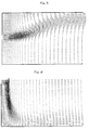
- FIGS 1 to 6 illustrate the flow configurations to which reference was made in the preamble to this description
- Figure 7 is a schematic perspective view, with partial removal of an improved rectangular decanter according to the present invention.
- FIGS 8 to 15 show the flow configurations obtained using the device which is the subject of the present invention and
- Figure 16 is a schematic sectional view through a vertical plane of the settling tank. On this cup, we figured the different planes of figures 8 to 15.
- the decanter rectangular shown in this figure is supplied with liquid via a supply channel 12.
- This channel supply feeds a plurality of intake chambers and energy dissipation such as 20, via a weir system designated as a whole by the reference 14.
- the supply chambers such as 20 are provided with a wall 18.
- Each of the energy intake and dissipation chambers such as 20 is preferably supplied with liquid through the channel 12, by means of an adjustable overhanging blade such as 26.
- the lowest row is positioned in relation to the raft 22 so as to avoid development of a background current likely to disturb the bed decanted materials depositing on the slab ("mud bed").
- this lower row of openings 16 is arranged at a height of between 1 / 3H and 2 / 3H, H being the height of the liquid in the structure (see diagram in figure 16).
- the row upper opening 16 ' is positioned to avoid any surface current likely to extend very far, without possibility of mixing with the rest of the fluid contained in the pelvis 10.
- this upper row of openings 16 ' is arranged at a height greater than 2/3 H and sufficient below the free surface of the liquid contained in the basin decantation.
- the distribution device described above can be supplemented by a staircase 24 whose height is calibrated so as to avoid any disturbance of the bed settled material settling on the slab 22.
- each of the intake and energy dissipation such as 20 is provided with an orifice drain 30.
- the principle underlying the device distribution according to the invention described above consists in cut each of the two eccentric jets (of the system type shown in Figures 5 and 6) in multiple jets which are easily controllable thanks to the presence weirs such as 26 aligned upstream of the division.
- FIGs 8 to 15 illustrate flow configurations obtained through the distribution system shown in the figure 7.
- the present invention is not limited to the embodiment described and shown. So in the example of realization described and represented here the settling tank has a rectangular shape, but however, this basin can present any other geometric shape or configuration, notably square, circular or other.
Landscapes
- Chemical Kinetics & Catalysis (AREA)
- Chemical & Material Sciences (AREA)
- Centrifugal Separators (AREA)
- Supply Devices, Intensifiers, Converters, And Telemotors (AREA)
- Rotary Pumps (AREA)
- Float Valves (AREA)
- Hydroponics (AREA)
- Fuel Cell (AREA)
- Processing Of Solid Wastes (AREA)
- Cable Transmission Systems, Equalization Of Radio And Reduction Of Echo (AREA)
- Fluidized-Bed Combustion And Resonant Combustion (AREA)
- Devices And Processes Conducted In The Presence Of Fluids And Solid Particles (AREA)
- Extraction Or Liquid Replacement (AREA)
Description
- La géométrie de répartition du liquide à l'entrée du décanteur;
- Le dispositif de récupération du liquide traité;
- Le dispositif de récupération des matières décantées et leur recyclage;
- La disposition relative des trois dispositifs spécifiés ci-dessus.
- une rangée d'ouvertures supérieures telles que 16' et,
- une rangée d'ouvertures inférieures telles que 16, disposées en quinconce par rapport aux ouvertures 16' de la rangée supérieure.
- une régularisation très rapide des vitesses du jet dans toute la section de l'ouvrage ;
- une réduction des vitesses en fond d'ouvrage se traduisant par le fait que les matières décantées (lit de boue) ne sont pas perturbées ;
- une dissipation naturelle de l'énergie d'entrée grâce à l'interaction entre les jets ;
- une création d'une zone de mélange limitée à l'entrée de l'ouvrage ;
- une minimisation des courants secondaires obtenue par le mélange immédiat du fluide entrant avec le fluide ambiant ;
- une répartition insensible aux variations de débit obtenue grâce à la présence des déversoirs tels que 26 qui permet à chaque ouverture 16, 16' du dispositif de répartition de recevoir une fraction déterminée du débit.
Claims (6)
- Décanteur notamment pour installations de traitements de liquides constitué d'un bassin de décantation (10) alimenté en liquide à partir d'un canal d'alimentation (12) et d'un déversoir (14), l'alimentation du liquide étant effectuée par l'intermédiaire du déversoir (14), positionné entre le canal d'alimentation (12) et des chambres d'admission (20) du liquide, ce dernier étant admis dans le bassin de décantation (10) par l'intermédiaire d'une pluralité d'ouvertures calibrées (16, 16') qui sont pratiquées respectivement dans les cloisons (18) des chambres d'admission (20) du liquide et alimentées en liquide à partir dudit déversoir (14) de manière que chaque ouverture reçoive une fraction déterminée du débit du liquide, lesdites ouvertures (16, 16') étant disposées selon au moins deux rangées horizontales de niveaux différents, les ouvertures de chaque rangée étant décalées par rapport aux ouvertures de la rangée adjacente, la rangée inférieure d'ouvertures (16) étant disposée à une hauteur comprise entre 1/3 H et 2/3 H, H étant la hauteur du liquide dans le bassin de décantation (10) et la rangée supérieure d'ouvertures (16') étant disposée à une hauteur supérieure à 2/3 H et suffisamment en dessous de la surface libre du liquide contenu dans le bassin de décantation.
- Décanteur selon la revendication 1 caractérisé en ce que la rangée d'ouvertures (16) horizontales la plus basse est positionnée, par rapport au radier (22) du bassin de décantation (10), à un niveau choisi de manière à éviter le développement d'un courant de fond susceptible de perturber le lit des matières décantées se déposant sur le radier.
- Décanteur selon la revendication 1 caractérisé en ce que la rangée d'ouvertures horizontales la plus haute (16') est positionnée par rapport à la surface du liquide dans le bassin de décantation, à un niveau choisi de manière à éviter tout courant de surface susceptible de se propager très loin sans se mélanger avec le reste du fluide.
- Décanteur selon l'une quelconque des revendications précédentes caractérisé en ce que le système de répartition du liquide comporte en outre une marche d'escalier (24), au-dessus du radier (10), dont la hauteur est calibrée de manière à éviter toute perturbation du lit de matières décantées se déposant sur le radier.
- Décanteur selon l'une quelconque des revendications précédentes caractérisé en ce que chacune desdites ouvertures (16, 16') est munie de moyens de réglage et de distribution de la vitesse du jet (28).
- Décanteur selon l'une quelconque des revendications précédentes caractérisé en ce que chacune des chambres d'admission et de dissipation d'énergie (20) est alimentée en liquide par le canal d'alimentation (12), par l'intermédiaire d'une lame déversante réglable (26).
Applications Claiming Priority (2)
| Application Number | Priority Date | Filing Date | Title |
|---|---|---|---|
| FR9314815 | 1993-12-09 | ||
| FR9314815A FR2713507B1 (fr) | 1993-12-09 | 1993-12-09 | Perfectionnements apportés aux décanteurs. |
Publications (2)
| Publication Number | Publication Date |
|---|---|
| EP0657196A1 EP0657196A1 (fr) | 1995-06-14 |
| EP0657196B1 true EP0657196B1 (fr) | 1998-01-21 |
Family
ID=9453763
Family Applications (1)
| Application Number | Title | Priority Date | Filing Date |
|---|---|---|---|
| EP94402640A Expired - Lifetime EP0657196B1 (fr) | 1993-12-09 | 1994-11-18 | Perfectionnements apportés aux décanteurs |
Country Status (7)
| Country | Link |
|---|---|
| US (1) | US5620600A (fr) |
| EP (1) | EP0657196B1 (fr) |
| AT (1) | ATE162415T1 (fr) |
| CA (1) | CA2137612A1 (fr) |
| DE (2) | DE657196T1 (fr) |
| ES (1) | ES2072844T3 (fr) |
| FR (1) | FR2713507B1 (fr) |
Families Citing this family (10)
| Publication number | Priority date | Publication date | Assignee | Title |
|---|---|---|---|---|
| GB9624867D0 (en) * | 1996-11-29 | 1997-01-15 | Kvaerner Paladon Limited | Separator |
| EP0953370B1 (fr) * | 1998-04-27 | 2002-03-27 | Emschergenossenschaft Lippeverband | Procédé d'opérer un bassin de sédimentation à fond rectangulaire des boues des eaux usées |
| WO2002041966A1 (fr) * | 2000-06-15 | 2002-05-30 | Compania Minera Antamina S.A. | Systeme de deversoir pour boues |
| ES2360363T3 (es) * | 2002-04-04 | 2011-06-03 | Hydrograv Gmbh | Piscina de decantación. |
| US7527726B2 (en) * | 2006-01-25 | 2009-05-05 | Q'max Solutions Inc. | Fluid treatment apparatus |
| CA2608798A1 (fr) * | 2007-04-16 | 2008-10-16 | Ambrose Ralph | Procede et appareillage d'elimination des solides en suspension de fluides aqueux |
| KR100971879B1 (ko) * | 2008-03-25 | 2010-07-22 | 권중천 | 자가 응집기능의 장방형 침전시스템 |
| WO2012142648A1 (fr) * | 2011-04-20 | 2012-10-26 | Hatch Associates Pty Ltd | Réseau de distribution destiné à être utilisé dans une zone de décantation d'un mélangeur-décanteur |
| WO2012142649A1 (fr) * | 2011-04-20 | 2012-10-26 | Hatch Associates Pty Ltd | Appareil de prévention du réentraînement |
| EP3610936B1 (fr) | 2018-08-14 | 2023-05-24 | hydrograv GmbH | Bassin de sédimentation et procédé de guidage de courants partiels dans une zone d'admission du bassin de sédimentation |
Family Cites Families (12)
| Publication number | Priority date | Publication date | Assignee | Title |
|---|---|---|---|---|
| FR576908A (fr) * | 1923-12-29 | 1924-08-28 | Dispositif d'épuration des eaux d'égouts par le procédé à l'eau fraîche | |
| US2118157A (en) * | 1934-12-24 | 1938-05-24 | Jeffrey Mfg Co | Apparatus for purifying liquids |
| NL74231C (fr) * | 1949-08-09 | |||
| US3963624A (en) * | 1974-01-07 | 1976-06-15 | Telecommunications Industries, Inc. | Clarifier |
| US4059529A (en) * | 1976-05-17 | 1977-11-22 | Sybron Corporation | Baffle for water or sewage settling tanks |
| US4056477A (en) * | 1976-06-21 | 1977-11-01 | Riga, Inc. | Separating apparatus for clarifying liquid |
| FR2487926B2 (fr) * | 1980-07-31 | 1986-04-25 | Verbiese | Perfectionnement au dispositif permettant l'etablissement d'une loi de repartition determinee du debit dans une veine liquide |
| US4366058A (en) * | 1981-06-02 | 1982-12-28 | Donaldson Company, Inc. | High efficiency settling system |
| JPS62143627A (ja) * | 1985-12-18 | 1987-06-26 | 加藤 博 | さけ・ます等の人工飼育池の池底自動清掃装置 |
| EP0248959B1 (fr) * | 1986-06-13 | 1990-11-14 | Harold James Beard | Dispositif de réglage de la turbulence pour un clarificateur intégré dans un canal |
| US4957628A (en) * | 1989-05-19 | 1990-09-18 | Schulz Christopher R | Apparatus for gravity separation of particles from liquid |
| US5362407A (en) * | 1993-04-15 | 1994-11-08 | Modern Welding Company, Inc. | Circular gravity clarifier and method |
-
1993
- 1993-12-09 FR FR9314815A patent/FR2713507B1/fr not_active Expired - Fee Related
-
1994
- 1994-11-18 AT AT94402640T patent/ATE162415T1/de not_active IP Right Cessation
- 1994-11-18 ES ES94402640T patent/ES2072844T3/es not_active Expired - Lifetime
- 1994-11-18 DE DE0657196T patent/DE657196T1/de active Pending
- 1994-11-18 EP EP94402640A patent/EP0657196B1/fr not_active Expired - Lifetime
- 1994-11-18 DE DE69408111T patent/DE69408111T2/de not_active Expired - Fee Related
- 1994-12-08 CA CA002137612A patent/CA2137612A1/fr not_active Abandoned
-
1996
- 1996-03-25 US US08/621,510 patent/US5620600A/en not_active Expired - Fee Related
Also Published As
| Publication number | Publication date |
|---|---|
| US5620600A (en) | 1997-04-15 |
| DE69408111T2 (de) | 1998-09-03 |
| DE657196T1 (de) | 1996-01-04 |
| ES2072844T1 (es) | 1995-08-01 |
| ES2072844T3 (es) | 1998-03-01 |
| ATE162415T1 (de) | 1998-02-15 |
| FR2713507A1 (fr) | 1995-06-16 |
| CA2137612A1 (fr) | 1995-06-10 |
| EP0657196A1 (fr) | 1995-06-14 |
| DE69408111D1 (de) | 1998-02-26 |
| FR2713507B1 (fr) | 1996-01-26 |
Similar Documents
| Publication | Publication Date | Title |
|---|---|---|
| EP1697053B1 (fr) | Procede et reacteur de traitement par floculation | |
| KR900001539B1 (ko) | 폐수의 생물학적 호기성 처리방법 및 그 장치 | |
| ES2434844T3 (es) | Dispositivo separador | |
| CA2137612A1 (fr) | Perfectionnements apportes aux decanteurs | |
| CA2159789A1 (fr) | Decanteur longitudinal a separation de flux | |
| CH619674A5 (fr) | ||
| FR2568489A1 (fr) | Procede de clarification a deux etages pour liquide charge de matieres solides | |
| CN110478978B (zh) | 一种圆形自排沙式重力沉沙过滤池 | |
| US9802140B2 (en) | Remote submerged chain conveyor | |
| CN113318489A (zh) | 一种矩形斜板二沉池 | |
| US7378027B2 (en) | Multilayer energy dissipating inlet column in center-feed clarifiers | |
| KR101898218B1 (ko) | 부상조와 침전조의 상호 교차 및 혼용 운전 가능한 다중 구조 수처리 장치 및 그 운전방법 | |
| EP0174232B1 (fr) | Procédé de clarification à lit de boue pour liquide chargé de matières solides | |
| PT626932E (pt) | Flutuacao por ar dissolvido | |
| JP2020062612A (ja) | 上向流傾斜板沈砂槽 | |
| KR102606033B1 (ko) | 하상 유도형 어도를 갖는 하천보 | |
| TW313560B (fr) | ||
| CN216778203U (zh) | 一种用于污水处理的沉淀池 | |
| EP0150646B1 (fr) | Installation pour le traitement par coagulation et floculation de liquides contenant des matières colloidales et/ou non colloidales | |
| JP2005194803A (ja) | 河川感潮部におけるヘドロ除去方法 | |
| JPH03143508A (ja) | 予備分離室をもつ沈澱槽 | |
| WO2009156669A2 (fr) | Procede et dispositif de separation des boues | |
| US2071320A (en) | Clarifier | |
| CN208865541U (zh) | 一种具有斜管沉淀与气浮处理的污水处理系统 | |
| US4663038A (en) | Side channel clarifier |
Legal Events
| Date | Code | Title | Description |
|---|---|---|---|
| PUAI | Public reference made under article 153(3) epc to a published international application that has entered the european phase |
Free format text: ORIGINAL CODE: 0009012 |
|
| AK | Designated contracting states |
Kind code of ref document: A1 Designated state(s): AT BE CH DE DK ES GB IT LI LU NL PT SE |
|
| ITCL | It: translation for ep claims filed |
Representative=s name: BARZANO' E ZANARDO MILANO S.P.A. |
|
| REG | Reference to a national code |
Ref country code: ES Ref legal event code: BA2A Ref document number: 2072844 Country of ref document: ES Kind code of ref document: T1 |
|
| GBC | Gb: translation of claims filed (gb section 78(7)/1977) | ||
| TCAT | At: translation of patent claims filed | ||
| 17P | Request for examination filed |
Effective date: 19951102 |
|
| DET | De: translation of patent claims | ||
| 17Q | First examination report despatched |
Effective date: 19960903 |
|
| GRAG | Despatch of communication of intention to grant |
Free format text: ORIGINAL CODE: EPIDOS AGRA |
|
| GRAH | Despatch of communication of intention to grant a patent |
Free format text: ORIGINAL CODE: EPIDOS IGRA |
|
| GRAH | Despatch of communication of intention to grant a patent |
Free format text: ORIGINAL CODE: EPIDOS IGRA |
|
| GRAA | (expected) grant |
Free format text: ORIGINAL CODE: 0009210 |
|
| AK | Designated contracting states |
Kind code of ref document: B1 Designated state(s): AT BE CH DE DK ES GB IT LI LU NL PT SE |
|
| PG25 | Lapsed in a contracting state [announced via postgrant information from national office to epo] |
Ref country code: NL Free format text: LAPSE BECAUSE OF FAILURE TO SUBMIT A TRANSLATION OF THE DESCRIPTION OR TO PAY THE FEE WITHIN THE PRESCRIBED TIME-LIMIT Effective date: 19980121 Ref country code: AT Free format text: LAPSE BECAUSE OF FAILURE TO SUBMIT A TRANSLATION OF THE DESCRIPTION OR TO PAY THE FEE WITHIN THE PRESCRIBED TIME-LIMIT Effective date: 19980121 |
|
| REF | Corresponds to: |
Ref document number: 162415 Country of ref document: AT Date of ref document: 19980215 Kind code of ref document: T |
|
| REG | Reference to a national code |
Ref country code: CH Ref legal event code: EP |
|
| ITF | It: translation for a ep patent filed | ||
| GBT | Gb: translation of ep patent filed (gb section 77(6)(a)/1977) |
Effective date: 19980129 |
|
| REF | Corresponds to: |
Ref document number: 69408111 Country of ref document: DE Date of ref document: 19980226 |
|
| REG | Reference to a national code |
Ref country code: ES Ref legal event code: FG2A Ref document number: 2072844 Country of ref document: ES Kind code of ref document: T3 |
|
| PG25 | Lapsed in a contracting state [announced via postgrant information from national office to epo] |
Ref country code: SE Free format text: LAPSE BECAUSE OF FAILURE TO SUBMIT A TRANSLATION OF THE DESCRIPTION OR TO PAY THE FEE WITHIN THE PRESCRIBED TIME-LIMIT Effective date: 19980421 Ref country code: DK Free format text: LAPSE BECAUSE OF FAILURE TO SUBMIT A TRANSLATION OF THE DESCRIPTION OR TO PAY THE FEE WITHIN THE PRESCRIBED TIME-LIMIT Effective date: 19980421 |
|
| REG | Reference to a national code |
Ref country code: PT Ref legal event code: SC4A Free format text: AVAILABILITY OF NATIONAL TRANSLATION Effective date: 19980316 |
|
| NLV1 | Nl: lapsed or annulled due to failure to fulfill the requirements of art. 29p and 29m of the patents act | ||
| PG25 | Lapsed in a contracting state [announced via postgrant information from national office to epo] |
Ref country code: LU Free format text: LAPSE BECAUSE OF NON-PAYMENT OF DUE FEES Effective date: 19981118 |
|
| PLBE | No opposition filed within time limit |
Free format text: ORIGINAL CODE: 0009261 |
|
| STAA | Information on the status of an ep patent application or granted ep patent |
Free format text: STATUS: NO OPPOSITION FILED WITHIN TIME LIMIT |
|
| 26N | No opposition filed | ||
| PGFP | Annual fee paid to national office [announced via postgrant information from national office to epo] |
Ref country code: BE Payment date: 20000913 Year of fee payment: 7 |
|
| PGFP | Annual fee paid to national office [announced via postgrant information from national office to epo] |
Ref country code: CH Payment date: 20001013 Year of fee payment: 7 |
|
| PGFP | Annual fee paid to national office [announced via postgrant information from national office to epo] |
Ref country code: PT Payment date: 20001026 Year of fee payment: 7 |
|
| PGFP | Annual fee paid to national office [announced via postgrant information from national office to epo] |
Ref country code: GB Payment date: 20001107 Year of fee payment: 7 |
|
| PGFP | Annual fee paid to national office [announced via postgrant information from national office to epo] |
Ref country code: ES Payment date: 20001120 Year of fee payment: 7 |
|
| PGFP | Annual fee paid to national office [announced via postgrant information from national office to epo] |
Ref country code: DE Payment date: 20010124 Year of fee payment: 7 |
|
| PG25 | Lapsed in a contracting state [announced via postgrant information from national office to epo] |
Ref country code: GB Free format text: LAPSE BECAUSE OF NON-PAYMENT OF DUE FEES Effective date: 20011118 |
|
| PG25 | Lapsed in a contracting state [announced via postgrant information from national office to epo] |
Ref country code: ES Free format text: LAPSE BECAUSE OF NON-PAYMENT OF DUE FEES Effective date: 20011119 |
|
| PG25 | Lapsed in a contracting state [announced via postgrant information from national office to epo] |
Ref country code: LI Free format text: LAPSE BECAUSE OF NON-PAYMENT OF DUE FEES Effective date: 20011130 Ref country code: CH Free format text: LAPSE BECAUSE OF NON-PAYMENT OF DUE FEES Effective date: 20011130 Ref country code: BE Free format text: LAPSE BECAUSE OF NON-PAYMENT OF DUE FEES Effective date: 20011130 |
|
| REG | Reference to a national code |
Ref country code: GB Ref legal event code: IF02 |
|
| BERE | Be: lapsed |
Owner name: DEGREMONT Effective date: 20011130 |
|
| PG25 | Lapsed in a contracting state [announced via postgrant information from national office to epo] |
Ref country code: PT Free format text: LAPSE BECAUSE OF NON-PAYMENT OF DUE FEES Effective date: 20020531 |
|
| PG25 | Lapsed in a contracting state [announced via postgrant information from national office to epo] |
Ref country code: DE Free format text: LAPSE BECAUSE OF NON-PAYMENT OF DUE FEES Effective date: 20020702 |
|
| GBPC | Gb: european patent ceased through non-payment of renewal fee |
Effective date: 20011118 |
|
| REG | Reference to a national code |
Ref country code: CH Ref legal event code: PL |
|
| REG | Reference to a national code |
Ref country code: PT Ref legal event code: MM4A Free format text: LAPSE DUE TO NON-PAYMENT OF FEES Effective date: 20020531 |
|
| REG | Reference to a national code |
Ref country code: ES Ref legal event code: FD2A Effective date: 20021213 |
|
| PG25 | Lapsed in a contracting state [announced via postgrant information from national office to epo] |
Ref country code: IT Free format text: LAPSE BECAUSE OF NON-PAYMENT OF DUE FEES;WARNING: LAPSES OF ITALIAN PATENTS WITH EFFECTIVE DATE BEFORE 2007 MAY HAVE OCCURRED AT ANY TIME BEFORE 2007. THE CORRECT EFFECTIVE DATE MAY BE DIFFERENT FROM THE ONE RECORDED. Effective date: 20051118 |