EP0657205B1 - Pervaporation mit einer kondensierbaren Gegenstromspülung - Google Patents
Pervaporation mit einer kondensierbaren Gegenstromspülung Download PDFInfo
- Publication number
- EP0657205B1 EP0657205B1 EP94309082A EP94309082A EP0657205B1 EP 0657205 B1 EP0657205 B1 EP 0657205B1 EP 94309082 A EP94309082 A EP 94309082A EP 94309082 A EP94309082 A EP 94309082A EP 0657205 B1 EP0657205 B1 EP 0657205B1
- Authority
- EP
- European Patent Office
- Prior art keywords
- component
- feed
- membrane
- stream
- pervaporation
- Prior art date
- Legal status (The legal status is an assumption and is not a legal conclusion. Google has not performed a legal analysis and makes no representation as to the accuracy of the status listed.)
- Expired - Lifetime
Links
- 238000005373 pervaporation Methods 0.000 title claims description 44
- 239000012528 membrane Substances 0.000 claims description 80
- 238000000034 method Methods 0.000 claims description 72
- 239000012466 permeate Substances 0.000 claims description 71
- 239000000203 mixture Substances 0.000 claims description 65
- 239000007788 liquid Substances 0.000 claims description 38
- XLYOFNOQVPJJNP-UHFFFAOYSA-N water Substances O XLYOFNOQVPJJNP-UHFFFAOYSA-N 0.000 claims description 29
- 238000000926 separation method Methods 0.000 claims description 25
- 239000012465 retentate Substances 0.000 claims description 19
- 150000002894 organic compounds Chemical class 0.000 claims description 10
- 238000004821 distillation Methods 0.000 claims description 9
- 238000010908 decantation Methods 0.000 claims description 5
- 238000009833 condensation Methods 0.000 claims description 4
- 230000005494 condensation Effects 0.000 claims description 4
- 238000000605 extraction Methods 0.000 claims description 4
- 239000012808 vapor phase Substances 0.000 claims description 4
- 238000010521 absorption reaction Methods 0.000 claims description 3
- 238000001704 evaporation Methods 0.000 claims description 3
- 230000008020 evaporation Effects 0.000 claims description 3
- 238000007710 freezing Methods 0.000 claims description 3
- 230000008014 freezing Effects 0.000 claims description 3
- 238000001179 sorption measurement Methods 0.000 claims description 3
- 238000002425 crystallisation Methods 0.000 claims description 2
- 230000008025 crystallization Effects 0.000 claims description 2
- 238000001223 reverse osmosis Methods 0.000 claims 1
- CSCPPACGZOOCGX-UHFFFAOYSA-N Acetone Chemical compound CC(C)=O CSCPPACGZOOCGX-UHFFFAOYSA-N 0.000 description 36
- LFQSCWFLJHTTHZ-UHFFFAOYSA-N Ethanol Chemical compound CCO LFQSCWFLJHTTHZ-UHFFFAOYSA-N 0.000 description 16
- YXFVVABEGXRONW-UHFFFAOYSA-N Toluene Chemical compound CC1=CC=CC=C1 YXFVVABEGXRONW-UHFFFAOYSA-N 0.000 description 15
- -1 poly(butadieneacrylonitrile) Polymers 0.000 description 15
- 150000001875 compounds Chemical class 0.000 description 11
- 239000000463 material Substances 0.000 description 11
- 239000012510 hollow fiber Substances 0.000 description 10
- OKKJLVBELUTLKV-UHFFFAOYSA-N Methanol Chemical compound OC OKKJLVBELUTLKV-UHFFFAOYSA-N 0.000 description 9
- 230000000052 comparative effect Effects 0.000 description 8
- 239000012527 feed solution Substances 0.000 description 8
- KFZMGEQAYNKOFK-UHFFFAOYSA-N isopropyl alcohol Natural products CC(C)O KFZMGEQAYNKOFK-UHFFFAOYSA-N 0.000 description 8
- 239000000126 substance Substances 0.000 description 7
- UHOVQNZJYSORNB-UHFFFAOYSA-N Benzene Chemical compound C1=CC=CC=C1 UHOVQNZJYSORNB-UHFFFAOYSA-N 0.000 description 6
- XEKOWRVHYACXOJ-UHFFFAOYSA-N Ethyl acetate Chemical compound CCOC(C)=O XEKOWRVHYACXOJ-UHFFFAOYSA-N 0.000 description 6
- ZMXDDKWLCZADIW-UHFFFAOYSA-N N,N-Dimethylformamide Chemical compound CN(C)C=O ZMXDDKWLCZADIW-UHFFFAOYSA-N 0.000 description 6
- 239000002131 composite material Substances 0.000 description 6
- 230000004907 flux Effects 0.000 description 6
- 239000007789 gas Substances 0.000 description 6
- VLKZOEOYAKHREP-UHFFFAOYSA-N n-Hexane Chemical compound CCCCCC VLKZOEOYAKHREP-UHFFFAOYSA-N 0.000 description 6
- 230000035699 permeability Effects 0.000 description 6
- IJGRMHOSHXDMSA-UHFFFAOYSA-N Atomic nitrogen Chemical compound N#N IJGRMHOSHXDMSA-UHFFFAOYSA-N 0.000 description 4
- 229920001577 copolymer Polymers 0.000 description 4
- 238000009834 vaporization Methods 0.000 description 4
- 230000008016 vaporization Effects 0.000 description 4
- ZWEHNKRNPOVVGH-UHFFFAOYSA-N 2-Butanone Chemical compound CCC(C)=O ZWEHNKRNPOVVGH-UHFFFAOYSA-N 0.000 description 3
- QTBSBXVTEAMEQO-UHFFFAOYSA-N Acetic acid Chemical compound CC(O)=O QTBSBXVTEAMEQO-UHFFFAOYSA-N 0.000 description 3
- WEVYAHXRMPXWCK-UHFFFAOYSA-N Acetonitrile Chemical compound CC#N WEVYAHXRMPXWCK-UHFFFAOYSA-N 0.000 description 3
- YMWUJEATGCHHMB-UHFFFAOYSA-N Dichloromethane Chemical compound ClCCl YMWUJEATGCHHMB-UHFFFAOYSA-N 0.000 description 3
- ZMANZCXQSJIPKH-UHFFFAOYSA-N Triethylamine Chemical compound CCN(CC)CC ZMANZCXQSJIPKH-UHFFFAOYSA-N 0.000 description 3
- 238000009835 boiling Methods 0.000 description 3
- 230000007423 decrease Effects 0.000 description 3
- 238000004519 manufacturing process Methods 0.000 description 3
- 239000000243 solution Substances 0.000 description 3
- QGZKDVFQNNGYKY-UHFFFAOYSA-N Ammonia Chemical compound N QGZKDVFQNNGYKY-UHFFFAOYSA-N 0.000 description 2
- CURLTUGMZLYLDI-UHFFFAOYSA-N Carbon dioxide Chemical compound O=C=O CURLTUGMZLYLDI-UHFFFAOYSA-N 0.000 description 2
- YNQLUTRBYVCPMQ-UHFFFAOYSA-N Ethylbenzene Chemical compound CCC1=CC=CC=C1 YNQLUTRBYVCPMQ-UHFFFAOYSA-N 0.000 description 2
- FXHOOIRPVKKKFG-UHFFFAOYSA-N N,N-Dimethylacetamide Chemical compound CN(C)C(C)=O FXHOOIRPVKKKFG-UHFFFAOYSA-N 0.000 description 2
- SECXISVLQFMRJM-UHFFFAOYSA-N N-Methylpyrrolidone Chemical compound CN1CCCC1=O SECXISVLQFMRJM-UHFFFAOYSA-N 0.000 description 2
- 239000004952 Polyamide Substances 0.000 description 2
- JUJWROOIHBZHMG-UHFFFAOYSA-N Pyridine Chemical compound C1=CC=NC=C1 JUJWROOIHBZHMG-UHFFFAOYSA-N 0.000 description 2
- 150000001298 alcohols Chemical class 0.000 description 2
- 235000011089 carbon dioxide Nutrition 0.000 description 2
- MVPPADPHJFYWMZ-UHFFFAOYSA-N chlorobenzene Chemical compound ClC1=CC=CC=C1 MVPPADPHJFYWMZ-UHFFFAOYSA-N 0.000 description 2
- 229920001971 elastomer Polymers 0.000 description 2
- 239000000835 fiber Substances 0.000 description 2
- 230000014509 gene expression Effects 0.000 description 2
- 229930195733 hydrocarbon Natural products 0.000 description 2
- 150000002430 hydrocarbons Chemical class 0.000 description 2
- 229910010272 inorganic material Inorganic materials 0.000 description 2
- BDAGIHXWWSANSR-UHFFFAOYSA-N methanoic acid Natural products OC=O BDAGIHXWWSANSR-UHFFFAOYSA-N 0.000 description 2
- LQNUZADURLCDLV-UHFFFAOYSA-N nitrobenzene Chemical compound [O-][N+](=O)C1=CC=CC=C1 LQNUZADURLCDLV-UHFFFAOYSA-N 0.000 description 2
- 229910052757 nitrogen Inorganic materials 0.000 description 2
- TVMXDCGIABBOFY-UHFFFAOYSA-N octane Chemical compound CCCCCCCC TVMXDCGIABBOFY-UHFFFAOYSA-N 0.000 description 2
- 229920000435 poly(dimethylsiloxane) Polymers 0.000 description 2
- 229920002647 polyamide Polymers 0.000 description 2
- 229920002635 polyurethane Polymers 0.000 description 2
- 239000004814 polyurethane Substances 0.000 description 2
- 241000894007 species Species 0.000 description 2
- VZGDMQKNWNREIO-UHFFFAOYSA-N tetrachloromethane Chemical compound ClC(Cl)(Cl)Cl VZGDMQKNWNREIO-UHFFFAOYSA-N 0.000 description 2
- 239000003039 volatile agent Substances 0.000 description 2
- UOCLXMDMGBRAIB-UHFFFAOYSA-N 1,1,1-trichloroethane Chemical class CC(Cl)(Cl)Cl UOCLXMDMGBRAIB-UHFFFAOYSA-N 0.000 description 1
- OSWFIVFLDKOXQC-UHFFFAOYSA-N 4-(3-methoxyphenyl)aniline Chemical compound COC1=CC=CC(C=2C=CC(N)=CC=2)=C1 OSWFIVFLDKOXQC-UHFFFAOYSA-N 0.000 description 1
- ZCYVEMRRCGMTRW-UHFFFAOYSA-N 7553-56-2 Chemical compound [I] ZCYVEMRRCGMTRW-UHFFFAOYSA-N 0.000 description 1
- WKBOTKDWSSQWDR-UHFFFAOYSA-N Bromine atom Chemical compound [Br] WKBOTKDWSSQWDR-UHFFFAOYSA-N 0.000 description 1
- 229920002101 Chitin Polymers 0.000 description 1
- XDTMQSROBMDMFD-UHFFFAOYSA-N Cyclohexane Chemical compound C1CCCCC1 XDTMQSROBMDMFD-UHFFFAOYSA-N 0.000 description 1
- 229920004449 Halon® Polymers 0.000 description 1
- 244000043261 Hevea brasiliensis Species 0.000 description 1
- 238000012695 Interfacial polymerization Methods 0.000 description 1
- 229920000459 Nitrile rubber Polymers 0.000 description 1
- CTQNGGLPUBDAKN-UHFFFAOYSA-N O-Xylene Chemical compound CC1=CC=CC=C1C CTQNGGLPUBDAKN-UHFFFAOYSA-N 0.000 description 1
- 239000004642 Polyimide Substances 0.000 description 1
- 239000004743 Polypropylene Substances 0.000 description 1
- 239000004372 Polyvinyl alcohol Substances 0.000 description 1
- XSTXAVWGXDQKEL-UHFFFAOYSA-N Trichloroethylene Chemical group ClC=C(Cl)Cl XSTXAVWGXDQKEL-UHFFFAOYSA-N 0.000 description 1
- 235000013334 alcoholic beverage Nutrition 0.000 description 1
- 150000001336 alkenes Chemical class 0.000 description 1
- 150000001412 amines Chemical class 0.000 description 1
- 229910021529 ammonia Inorganic materials 0.000 description 1
- 230000009286 beneficial effect Effects 0.000 description 1
- GDTBXPJZTBHREO-UHFFFAOYSA-N bromine Substances BrBr GDTBXPJZTBHREO-UHFFFAOYSA-N 0.000 description 1
- 229910052794 bromium Inorganic materials 0.000 description 1
- 239000000919 ceramic Substances 0.000 description 1
- 238000003889 chemical engineering Methods 0.000 description 1
- 238000001311 chemical methods and process Methods 0.000 description 1
- 150000008280 chlorinated hydrocarbons Chemical class 0.000 description 1
- 239000011248 coating agent Substances 0.000 description 1
- 238000000576 coating method Methods 0.000 description 1
- 239000000470 constituent Substances 0.000 description 1
- 239000002285 corn oil Substances 0.000 description 1
- 235000005687 corn oil Nutrition 0.000 description 1
- 150000001896 cresols Chemical class 0.000 description 1
- 230000018044 dehydration Effects 0.000 description 1
- 238000006297 dehydration reaction Methods 0.000 description 1
- 238000010586 diagram Methods 0.000 description 1
- 238000003618 dip coating Methods 0.000 description 1
- 239000003814 drug Substances 0.000 description 1
- 239000000284 extract Substances 0.000 description 1
- 238000001125 extrusion Methods 0.000 description 1
- 238000000855 fermentation Methods 0.000 description 1
- 230000004151 fermentation Effects 0.000 description 1
- 239000012847 fine chemical Substances 0.000 description 1
- 239000000796 flavoring agent Substances 0.000 description 1
- 235000019634 flavors Nutrition 0.000 description 1
- 229920001973 fluoroelastomer Polymers 0.000 description 1
- 235000019253 formic acid Nutrition 0.000 description 1
- 239000003205 fragrance Substances 0.000 description 1
- 238000010438 heat treatment Methods 0.000 description 1
- 229920001477 hydrophilic polymer Polymers 0.000 description 1
- 230000002209 hydrophobic effect Effects 0.000 description 1
- 239000012535 impurity Substances 0.000 description 1
- 150000002484 inorganic compounds Chemical class 0.000 description 1
- 239000011147 inorganic material Substances 0.000 description 1
- 229910052740 iodine Inorganic materials 0.000 description 1
- 239000011630 iodine Substances 0.000 description 1
- 239000003014 ion exchange membrane Substances 0.000 description 1
- 125000001449 isopropyl group Chemical group [H]C([H])([H])C([H])(*)C([H])([H])[H] 0.000 description 1
- 150000002576 ketones Chemical class 0.000 description 1
- 230000007774 longterm Effects 0.000 description 1
- 239000002184 metal Substances 0.000 description 1
- 229910052751 metal Inorganic materials 0.000 description 1
- 150000002739 metals Chemical class 0.000 description 1
- SYSQUGFVNFXIIT-UHFFFAOYSA-N n-[4-(1,3-benzoxazol-2-yl)phenyl]-4-nitrobenzenesulfonamide Chemical class C1=CC([N+](=O)[O-])=CC=C1S(=O)(=O)NC1=CC=C(C=2OC3=CC=CC=C3N=2)C=C1 SYSQUGFVNFXIIT-UHFFFAOYSA-N 0.000 description 1
- 229920003052 natural elastomer Polymers 0.000 description 1
- 229930014626 natural product Natural products 0.000 description 1
- 229920001194 natural rubber Polymers 0.000 description 1
- 239000003921 oil Substances 0.000 description 1
- 235000019198 oils Nutrition 0.000 description 1
- 150000007524 organic acids Chemical class 0.000 description 1
- 235000005985 organic acids Nutrition 0.000 description 1
- 229920000620 organic polymer Polymers 0.000 description 1
- 239000003960 organic solvent Substances 0.000 description 1
- 238000010422 painting Methods 0.000 description 1
- 239000003209 petroleum derivative Substances 0.000 description 1
- 238000005191 phase separation Methods 0.000 description 1
- 150000002989 phenols Chemical class 0.000 description 1
- PJGSXYOJTGTZAV-UHFFFAOYSA-N pinacolone Chemical compound CC(=O)C(C)(C)C PJGSXYOJTGTZAV-UHFFFAOYSA-N 0.000 description 1
- 229920002492 poly(sulfone) Polymers 0.000 description 1
- 229920001197 polyacetylene Polymers 0.000 description 1
- 229920002239 polyacrylonitrile Polymers 0.000 description 1
- 229920002480 polybenzimidazole Polymers 0.000 description 1
- 229920000570 polyether Polymers 0.000 description 1
- 229920001721 polyimide Polymers 0.000 description 1
- 229920000642 polymer Polymers 0.000 description 1
- 229920001155 polypropylene Polymers 0.000 description 1
- 229920001296 polysiloxane Polymers 0.000 description 1
- 229920002451 polyvinyl alcohol Polymers 0.000 description 1
- 235000019422 polyvinyl alcohol Nutrition 0.000 description 1
- 239000005373 porous glass Substances 0.000 description 1
- 238000000746 purification Methods 0.000 description 1
- UMJSCPRVCHMLSP-UHFFFAOYSA-N pyridine Natural products COC1=CC=CN=C1 UMJSCPRVCHMLSP-UHFFFAOYSA-N 0.000 description 1
- 238000011084 recovery Methods 0.000 description 1
- 238000005057 refrigeration Methods 0.000 description 1
- 239000005060 rubber Substances 0.000 description 1
- 239000008159 sesame oil Substances 0.000 description 1
- 235000011803 sesame oil Nutrition 0.000 description 1
- 229920002379 silicone rubber Polymers 0.000 description 1
- 239000004945 silicone rubber Substances 0.000 description 1
- 239000002904 solvent Substances 0.000 description 1
- 238000000807 solvent casting Methods 0.000 description 1
- 238000005507 spraying Methods 0.000 description 1
- UBOXGVDOUJQMTN-UHFFFAOYSA-N trichloroethylene Natural products ClCC(Cl)Cl UBOXGVDOUJQMTN-UHFFFAOYSA-N 0.000 description 1
- 239000002351 wastewater Substances 0.000 description 1
- 239000008096 xylene Substances 0.000 description 1
Images


Classifications
-
- B—PERFORMING OPERATIONS; TRANSPORTING
- B01—PHYSICAL OR CHEMICAL PROCESSES OR APPARATUS IN GENERAL
- B01D—SEPARATION
- B01D61/00—Processes of separation using semi-permeable membranes, e.g. dialysis, osmosis or ultrafiltration; Apparatus, accessories or auxiliary operations specially adapted therefor
- B01D61/36—Pervaporation; Membrane distillation; Liquid permeation
- B01D61/362—Pervaporation
Definitions
- Pervaporation is a membrane-based process that can be used to remove a vaporizable component from a liquid mixture.
- water containing low concentrations of at least one organic compound is fed at essentially ambient pressure to the feed side of a membrane, while a vacuum pump or a gaseous sweep stream maintains a sufficiently low partial pressure of the organic compound on the permeate side of the membrane to provide a chemical potential gradient of the organic compound across the membrane.
- the organic compound and some of the water vaporize from the permeate side of the membrane to form a vapor-phase permeate.
- a noncondensable sweep gas has been used to provide the driving force for the transport of vaporizable components across a pervaporation membrane. Although such a practice eliminates the vacuum pump-related problems associated with pervaporation, it introduces other problems associated with separating the condensable permeate from the noncondensable sweep gas. See, for example, Hoover et al., 10 J. Memb. Sci. 253 (1982).
- Lee et al. in U.S. Patent Nos. 4,933,198, 5,013,447 and 5,143,526, disclose a process for treating alcoholic beverages by pervaporation using a noncondensable sweep gas or vacuum.
- the sweep gas streams disclosed by Lee et al. may comprise water or ethanol, conditions in the sweep gas stream are controlled to ensure that these components are present only as noncondensable gas vapors and thus, no advantage from the use of a condensable sweep was recognized.
- the present invention demonstrates that a pervaporation process utilizing a condensable vapor sweep is feasible.
- the present invention solves the problems associated with pervaporation processes by using a countercurrent condensable vapor sweep stream to provide and maintain the chemical potential gradient across the membrane. Another feature of the present invention is that the use of a condensable vapor sweep stream can provide a portion of the heat energy required for vaporization of the permeate.
- the invention comprises a process for the removal of at least one component of a liquid mixture, comprising directing a liquid mixture against the feed side of a membrane, directing a condensable vapor sweep stream past the permeate side of the membrane in a manner such that the flow of the condensable vapor sweep is substantially countercurrent to the flow of the liquid mixture, thereby transporting at least a portion of at least one component of the liquid mixture from the feed side to the permeate side of the membrane to form a combined permeate side mixture of condensable vapor and at least one transported component, and collecting the combined permeate side mixture.
- the transported component can then be recovered by separating the transported component from the combined permeate side mixture.
- pervaporation performed in accordance with the present invention results in significantly higher permeate fluxes due to increased driving force, while maintaining the same or greater separation factor, and assists in maintaining the temperature of the feed stream sufficiently high.
- the use of a condensable vapor sweep stream allows the driving force for transport to be maintained without the need for high vacuum.
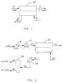
- FIGS. 1-12 are schematic diagrams of exemplary systems for conducting the countercurrent condensable sweep pervaporation process of the present invention.
- FIG. 1 depicts a system wherein a feed stream 10 containing at least two components A and B is fed to a membrane module 25.
- a condensable vapor sweep stream 32 is fed to the permeate side of the membrane module 25 at a vapor inlet port located near the retentate end of the module so as to flow countercurrent to the feed stream.
- One of the components of the feed stream (component A) is selectively removed in the membrane module, producing a retentate stream 14 depleted in component A ("A-poor").
- Condensable vapor sweep stream 32 is combined with the vaporous permeate enriched in component A ("A-rich") from the membrane module, producing a combined permeate side mixture 34 which exits from the module at a vapor outlet port located near the feed end of the module.
- A-rich vaporous permeate enriched in component A
- FIG. 2 depicts a system wherein a feed stream 10 containing at least two components is circulated by circulation pump 21 and heated in heater 23 to form a heated stream 12. Heated stream 12 is circulated to a membrane module 25. A condensable vapor sweep stream 32 is fed to the permeate side of the membrane module 25 at a vapor inlet port located near the retentate end of the module so as to flow countercurrent to the feed stream. One of the components of the feed stream (component A) is selectively removed in the membrane module, producing a retentate stream 14 depleted in component A.
- Condensable vapor sweep stream 32 is combined with the vaporous permeate enriched in component A from the membrane module, producing a combined permeate side mixture 34 which exits from the membrane module at a vapor outlet port located near the feed end of the module.
- Combined permeate side mixture 34 then enters a condenser 29, where the combined permeate side mixture is condensed to form condensed permeate 36.
- Condensed permeate 36 is directed to a separation apparatus 28, producing a stream 38 enriched in component A, and a stream 39 depleted in component A.
- FIG. 3 is a schematic of a system that is essentially the same as the system depicted in FIG. 2, except that the condensable vapor sweep stream 32 is produced from a liquid stream 30 using a vapor generator 27. Additionally, FIG. 3 shows a stream of noncondensable components 35, which may have entered the system, exiting condenser 29. These noncondensable components are then removed using vacuum pump 26.
- FIG. 4 is a schematic of a system that is also essentially the same as the system depicted in FIG. 2 except that a portion 16 of the depleted retentate stream 14 is used for the condensable vapor sweep stream 32.
- FIG. 5 is a schematic of a system that is essentially the same as the system depicted in FIG. 3 except that a portion 16 of the depleted retentate stream 14 is used for the condensable vapor sweep stream 32.
- FIG. 6 depicts a system similar to the system depicted in FIG. 5 except that a decantation/phase separation apparatus 40 is specified as the separation apparatus.
- This embodiment is useful when component A is not 100% miscible with the liquid used to form the condensable vapor sweep stream.
- the purified component A 38 is withdrawn from the decantation process, while the stream 39 depleted in component A is recycled to the feed stream 10.
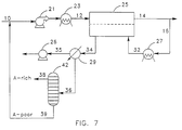
- FIG. 7 shows a system similar to the system depicted in FIG. 4 except that a distillation/evaporation apparatus 42 is specified as the separation apparatus. This embodiment is useful when component A is 100% miscible with the liquid used to form the condensable vapor sweep stream.
- the purified component A 38 is removed from the distillation process, while the stream 39 depleted in component A is recycled to the feed stream.
- FIG. 8 depicts essentially the same system as shown in FIG. 3 except that stream 39 depleted in component A from separation apparatus 28 is directed to a vapor generator 27 to produce condensable vapor sweep stream 32.
- FIG. 9 depicts a system wherein a feed stream 60 containing at least two components is first fed to a conventional pervaporation membrane module 55.
- One of the components of the feed stream (component A) is selectively removed in the module 55, producing a retentate stream 64 partially depleted in component A and a vaporous permeate stream 74 enriched in component A.
- the partially depleted retentate stream 64 is fed to a countercurrent condensable sweep membrane module 25 of the present invention.
- a condensable vapor sweep stream 32 is fed to the permeate side of module 25 at a vapor inlet port located near the retentate end of the module so as to flow countercurrent to the feed stream.
- Component A is selectively removed in module 25, producing a retentate stream 14 depleted in component A.
- Condensable vapor sweep stream 32 is combined with the vaporous permeate enriched in component A from module 25, producing a combined permeate side mixture 34 which exits from module 25 at a vapor outlet port located near its feed end.
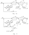
- FIG. 10 is a schematic of a system that is essentially the same as that depicted in FIG. 9 except that the condensable vapor sweep stream 32 is produced from a portion 16 of the depleted retentate stream 14 using vapor-generator 27. Additionally, FIG. 10 shows the combined permeate side mixture 34 entering a condenser 29, where the combined permeate side mixture is condensed to form condensed permeate 36. The condensed permeate 36 is then recycled to the feed to the conventional pervaporation module 55. FIG. 10 also shows the vaporous permeate stream 74 from the conventional pervaporation module 55 entering a condenser 59, producing a condensed permeate 76. FIG. 10 also includes a stream of noncondensable components 75, which may have entered the system, exiting condenser 59. These noncondensable components are then removed using a vacuum pump 56.
- FIG. 11 is a schematic of a system that is essentially the same as that depicted in FIG. 10 except that the condensed permeate 36 is directed to a separation apparatus 28, producing a stream 38 enriched in component A, and a stream 39 depleted in component A, stream 39 then being recycled to the feed to the conventional pervaporation module 55.
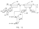
- FIG. 12 is a schematic of a system that is essentially the same as the system depicted in FIG. 11 except that the stream 39 depleted in component A is recycled to the feed to the countercurrent condensable sweep module 25.
- the liquid mixture comprising the feed stream to the membrane selected for the pervaporation process may be a mixture of at least one organic component with water, or a mixture of organic components.
- This feed stream may derive from a variety of sources including, but not limited to, industrial process wastewaters, chemical process liquids, the production of fine chemicals, the production of pharmaceuticals, the recovery or purification of flavors and fragrances from natural products, or fermentation processes.
- the separation to be achieved by the countercurrent sweep pervaporation process of the present invention may be the removal of volatile compounds from water, the removal of water from organics (also known as dehydration of organics), or the separation of organic mixtures.
- the membrane used is selected such that the minor component of the feed stream is selectively removed by the membrane; however, the invention need not be so limited.
- the volatile compound to be removed can be virtually any compound with sufficient volatility to be removed by pervaporation. Generally, this includes compounds with boiling points that are less than about 200°C.
- Examples of compounds that can be removed from water by the process of the present invention include, but are not limited to, chlorofluorocarbons such as Freons and Halons; chlorinated hydrocarbons, such as methylene chloride, trichloroethylene, trichloroethanes, carbon tetrachloride, chlorobenzene; nonchlorinated hydrophobic organics, such as benzene, toluene, xylene, ethyl benzene, cyclohexane, hexane and octane; nonchlorinated hydrophilic organics, such as methanol, ethanol, other alcohols, acetone, ethyl acetate, methyl ethyl ketone, methyl t-butyl ketone
- the organic can be virtually any compound. Examples include, but are not limited to, ethanol, methanol, other alcohols, acetone, ethyl acetate, dimethylacetamide, dimethylformamide, hydrocarbons such as hexane, octane, and petroleum distillates, as well as oils such as sesame oil and corn oil.
- the mixtures may comprise various organic species.
- Organic mixtures that can be separated include, but are not limited to, methanol from other organic solvents, mixtures of isomers and components from natural extracts, olefins from paraffins, and aromatics from non-aromatics, such as the removal of benzene from gasoline or other hydrocarbons.
- the membrane used in the process of the present invention can be virtually any material.
- the membrane is usually, but not always, an elastomeric or rubbery polymer.
- materials useful for such separations include, but are not limited to, natural rubber, nitrile rubber, polystyrene-butadiene copolymers, poly(butadieneacrylonitrile) rubber, polyurethanes, polyamides, polyacetylenes, poly(trimethylsilylpropyne), fluoroelastomers, poly(vinylchlorides), and polysiloxanes, including silicone rubber.
- Ion-exchange membranes may also be used for some applications.
- the selective membrane is usually very hydrophilic.
- materials useful for removing water from organics include, but are not limited to, polyvinylalcohol, cellulosic materials, chitin and derivatives thereof, polyurethanes, polyamides, poly(acrylic acids), poly(acrylates), poly(vinyl acetates), and polyethers. Blends and copolymers of these materials are also useful.
- the choice of membrane material will depend on the organics being separated. Many of the polymers listed above for removal of volatile compounds from water and for removal of water from organics may work well for separating certain organic mixtures. In particular, it is often common to use copolymers for separating organics since the ratio of so-called “hard” and “soft” segments can easily be adjusted to provide the desired selectivity.
- the membrane may be isotropic or asymmetric. Additionally, the membrane may be homogeneous or a multilayer composite. In most cases, it is preferred that the membrane material be crosslinked to provide sufficient resistance to the chemicals in the feed stream.
- the membrane may be made by a solvent phase-inversion process, thermally induced phase-inversion process, melt-extrusion process, or by a wet or dry solvent-casting process.
- the selective layer can be formed by dip-coating, painting, spray-coating, solution-coating, or by interfacial polymerization.
- the support layers that provide mechanical strength to the composite should give as little resistance to the transport of the permeating species through the selective layer as is technically feasible. Additionally, the support membrane should be chemically and thermally resistant, allowing for operation on hot feed streams containing various chemical constituents.
- Materials suitable for the support membrane include, but are not limited to, organic polymers such as polypropylene, polyacrylonitrile, poly(vinylidenefluorides), poly(etherimides), polyimides, polysulfones, poly(ethersulfones), poly(arylsulfones), poly(phenylquinoxalines), polybenzimidazoles, and copolymers and blends of these materials; and inorganic materials such as porous glass, ceramics, and metals.
- organic polymers such as polypropylene, polyacrylonitrile, poly(vinylidenefluorides), poly(etherimides), polyimides, polysulfones, poly(ethersulfones), poly(arylsulfones), poly(phenylquinoxalines), polybenzimidazoles, and copolymers and blends of these materials
- inorganic materials such as porous glass, ceramics, and metals.
- the membrane can be used in the form of a flat sheet or hollow fiber or tube.
- the membrane may be placed into a module designed to permit countercurrent flow of the permeate stream relative to the feed stream. This can include plate-and-frame modules or spiral-wound modules.
- the feed flow may be on the outside (shell side) or inside (tube side) of the fibers.
- a tube-side-feed hollow fiber module is especially preferred.
- the materials used in the membrane module should have sufficient chemical and thermal resistance to permit long-term operation.
- the feed stream is heated. Heating the feed stream raises the vapor pressure of the components of the feed mixture, which increases the driving force for transport across the membrane, leading to higher fluxes.
- the temperature to which the feed stream is heated will depend on the composition of the feed stream and the operating characteristics of the membrane material. In some cases, it is beneficial to slightly pressurize the feed stream so that the temperature of the feed can be raised above the boiling point of the feed at ambient pressure. For most applications, the temperature of the feed stream will be greater than 40°C and will typically be between 60° and 100°C.
- the process of the present invention is particularly useful for applications where each of the partial pressures of the more permeable components present in a vapor phase that is in equilibrium with the feed stream is less than about 100 mmHg. This is because as the more permeable component is removed from the feed stream, its partial pressure decreases, reducing the driving force for transport across the membrane.
- the driving force for transport is maintained without any need to reduce the total pressure of the permeate stream to a value less than that of each component.
- the process of the present invention will be effective for treating feed streams wherein the partial pressure of the more-permeable component is greater than 100 mmHg, the advantages over conventional pervaporation are not as great due to the higher driving force present with the higher partial pressure.
- condensable vapor may be used as a countercurrent sweep stream.
- condensable vapor is meant any compound with a boiling point greater than about -100°C.
- the condensable vapor may consist of one of the components of the liquid feed solution or it may be a compound that is not present in the feed solution.
- the condensable vapor may be either miscible or substantially immiscible with at least one component of the liquid mixture.
- the condensable vapor consists of one of the components of the feed solution that is not desired to be transported to the permeate side of the membrane.
- a portion of the retentate stream may be used to generate the condensable vapor used as the countercurrent sweep stream.
- the pressure and temperature of the countercurrent condensable vapor sweep may be set at any value so long as the sweep is a vapor when it enters the membrane module. In some applications, it is advantageous if they are selected such that a portion of the vapor condenses on the permeate side of the membrane. This allows for the heat of condensation to be transferred to the feed stream, resulting in a more constant temperature in the feed.
- the initial temperature of the sweep is preferably equal to or greater than the temperature of the liquid mixture directed against the feed side of the membrane.
- the volumetric flow of the condensable vapor at the vapor inlet port may be adjusted to provide the desired efficiency.
- the volumetric flow of the condensable vapor is at least 10% of the volumetric flow of the combined permeate side mixture.
- the volumetric flow is typically set such that the condensation of the condensable vapor provides at least 20% of the heat of vaporization required to remove components from the liquid mixture.
- the permeate side mixture may be collected by freezing or condensing the mixture, after which the transported component may be separated.
- This separation step may be performed by the most convenient method, such as by decantation, distillation, liquid/liquid extraction, evaporation, crystallization, freezing, adsorption, absorption, by extraction using a membrane contactor, or by another pervaporation process.
- the permeate-side mixture may be directed to a separation apparatus as a vapor.
- suitable separation means include, but are not limited to, distillation, fractional condensation, vapor permeation through a membrane, adsorption, and absorption.
- the process of the present invention may be used to perform the entire separation desired, or it may be combined with other processes in so-called "hybrid" systems.
- a conventional pervaporation process can be used to remove the bulk of one component from a feed stream, reducing the concentration such that the partial pressure of the component in equilibrium with the liquid stream is less than about 100 mmHg.
- the countercurrent condensable sweep pervaporation process of the present invention can then be used to reduce the concentration down to the desired level.
- the exact level to which the component is removed by the first separation process prior to removal by the countercurrent condensable sweep pervaporation process is determined by the relative convenience and cost of the two processes.
- various streams from the hybrid process may be recycled to other points within the process to improve efficiency, to improve the quality of the separation, or to reduce operating costs.
- the condensed permeate side mixture 36 is recycled back to the feed to the conventional pervaporation process. This option is attractive when the concentration of the component being removed from the feed stream (component A) in the condensed permeate-side mixture from the countercurrent pervaporation process 36 is close to the concentration of component A in the initial feed stream 60.
- FIG. 11 shows that the permeate side mixture 36 can first be separated into a stream 38 concentrated in component A and a stream 39 depleted in component A, which can then be recycled to the feed to the conventional pervaporation process.
- Another particularly attractive hybrid system comprises a distillation process coupled with the countercurrent pervaporation process of the present invention.
- the liquid exiting the top of the distillation column is sent to the countercurrent pervaporation process to remove remaining impurities.
- the permeate from the countercurrent pervaporation process, now enriched in component A, can be added directly into the distillation column at the appropriate position in the column.
- a feed solution 10 containing 8900 ppm acetone in water at 59°C and essentially ambient pressure was fed at a rate of 29 ml/min to the lumens of hollow fiber membranes in module 25.
- the module 25 comprised 183 composite hollow fibers with inside diameters of 365 ⁇ m. The effective length of the fibers was 40 cm.
- the inside surfaces of the hollow fibers were coated with a selective layer of crosslinked poly(dimethylsiloxane) (PDMS).
- PDMS crosslinked poly(dimethylsiloxane)
- a condensable water vapor sweep stream 32 at 60°C and 0.2 atm was introduced to the permeate side of the membrane at a vapor inlet port located near the retentate end of the module so as to flow substantially countercurrent to the flow of the feed.
- the flow rate of the water vapor sweep was set at 0.7 gm/min.
- a combined permeate side mixture 34 that comprised the condensable vapor sweep stream and the acetone that selectively permeated the membrane was withdrawn at a vapor outlet port located near the feed end of the module.
- the combined permeate side mixture 34 was sent to a first condenser 29 cooled with a dry ice/isopropyl alcohol (IPA) solution to a temperature of approximately -75°C. Any vapors not removed in this condenser were removed in a second condenser (not shown) cooled with liquid nitrogen to a temperature of approximately -195°C.
- a vacuum pump 26 was used to remove any noncondensable components that may have entered the system.
- the condensates from the dry ice/IPA and liquid nitrogen condensers were combined to form a single acetone solution 36.
- the retentate stream 14 was at a temperature of 58°C, resulting in a temperature drop of only 1°C.
- the retentate had an acetone concentration of 6300 ppm.
- Solution stream 36 had an acetone concentration of 107,000 ppm, which corresponds to a selectivity of 12 for acetone over water relative to the feed solution.
- the acetone permeability through the membrane was 1.8 x 10 -4 kg/m 2 -day-ppm.
- Example 1 For comparison, the system described in Example 1 was operated as a conventional pervaporation system, that is, with a vacuum on the permeate side but with the countercurrent condensable sweep flow set to 0, so that no water vapor was introduced as a condensable vapor sweep stream to the membrane module. The permeate was kept at a pressure of 0.2 atm.
- Table 1 Example Temp. Drop (°C) Selectivity Acetone Permeability (kg/m 2 -day-ppm) 1 1 12 1.8 x 10 -4 Comparative Example 1 6 15 0.5 x 10 -4
- Example 1 The system described in Example 1 was operated as described in Example 1 except that the feed solution consisted of 248 ppm toluene in water fed to the lumens of the hollow fiber membrane module at a rate of 28 ml/min.
- Example 6 For comparison, the system described in Example 6 was operated as described in Comparative Example 1 with the feed solution toluene concentration at 325 ppm. The results of this Comparative Example and of Example 6 are summarized in Table 3. Table 3 Example Temp. Drop (°C) Selectivity Toluene Permeability (kg/m 2 -day-ppm) 6 1 170 9.9 x 10 -4 Comparative Example 2 4 220 5.3 x 10 -4
- a feed solution 10 containing 4.9 wt% water in ethanol at 68°C at an absolute pressure of 1.26 atm was fed at a rate of 11.0 g/min to the lumens of hollow fiber membranes in module 25.
- the module 25 had an effective membrane area of 0.008 m 2 and comprised 40 composite hollow fibers with an effective length of 40 cm and the inside surfaces of the hollow fibers were coated with a hydrophilic polymer.
- a condensable ethanol vapor sweep stream 32 at 50°C and 0.1 atm was introduced to the permeate side of the membrane at a vapor inlet port located near the retentate end of the module so as to flow substantially countercurrent to the flow of the feed.
- the flow rate of the ethanol vapor sweep was set at 2.4 g/min.
- a combined permeate side mixture 34 that comprised the condensable vapor sweep stream and the water that selectively permeated the membrane was withdrawn at a vapor outlet port located near the feed end of the module.
- This combined permeate side mixture was condensed using the same method described in Example 1. Under these operating conditions, the water flux through the membrane was 22 kg/m 2 -day.
- Example 7 For comparison, the system described in Example 7 was operated as a conventional pervaporation system with a vacuum on the permeate side, but with the countercurrent condensable ethanol vapor sweep flow set to 0, so that no ethanol vapor was introduced to the membrane module. The pressure on the permeate side of the membrane was then adjusted to 0.01 atm, resulting in a water flux through the membrane that was the same as that obtained in Example 7. This illustrates that one-tenth the vacuum is required on the permeate side of the membrane with the countercurrent condensable vapor sweep process to achieve the same rate of transport through the membrane, resulting in lower capital and operating costs.
Landscapes
- Engineering & Computer Science (AREA)
- Water Supply & Treatment (AREA)
- Chemical & Material Sciences (AREA)
- Chemical Kinetics & Catalysis (AREA)
- Separation Using Semi-Permeable Membranes (AREA)
Claims (24)
- Pervaporationsverfahren zum Abtrennen wenigstens einer Komponente eines Flüssigkeitsgemischzulaufs, umfassend die folgenden Schritte(a) Vorsehen einer Membran, die eine Zulaufseite und eine Permeatseite aufweist,(b) Leiten des Flüssigkeitsgemischzulaufs zur Zulaufseite der Membran,(c) Leiten eines Spülstroms vorbei an der Permeatseite der Membran, wodurch wenigstens ein Teil der wenigstens einen Komponente des Flüssigkeitsgemischzulaufs von der Zulaufseite zur Permeatseite der Membran transportiert wird, um ein gemeinsames Gemisch aus dem Spülstrom und der wenigstens einen Komponente auf der Permeatseite zu bilden, und(d) Abziehen des gemeinsamen Permeatseitengemisches,dadurch gekennzeichnet, daß der Spülstrom ein kondensierbarer Dampf ist und daß der Fluß des Spülstroms weitgehend im Gegenstrom zum Fluß des Flüssigkeitsgemischzulaufs erfolgt.
- Verfahren nach Anspruch 1, dadurch gekennzeichnet, daß die Membran in bezug auf die wenigstens eine Komponente des Flüssigkeitsgemischzulaufs selektiv permeabel oder bezüglich sämtlicher Komponenten in dem Flüssigkeitsgemischzulauf gleich permeabel ist.
- Verfahren nach Anspruch 1, dadurch gekennzeichnet, daß der Druck auf der Permeatseite der Membran geringer als der Druck auf der Zulaufseite der Membran ist.
- Verfahren nach Anspruch 1, dadurch gekennzeichnet, daß die Konzentration und der Druck der wenigstens einen Komponente des Flüssigkeitsgemischzulaufs auf der Zulaufseite derart ausgebildet sind, daß der Partialdruck der wenigstens einen Komponente in einer hypothetischen Dampfphase im Gleichgewicht mit dem Flüssigkeitsgemischzulauf den Partialdruck der wenigstens einen Komponente auf der Permeatseite übersteigt.
- Verfahren nach Anspruch 1, dadurch gekennzeichnet, daß die Anfangstemperatur des kondensierbaren Dampfes gleich oder größer als die Temperatur des Flüssigkeitsgemischzulaufs ist.
- Verfahren nach Anspruch 1, dadurch gekennzeichnet, daß der Druck und die Temperatur des kondensierbaren Dampfes derart ausgewählt werden, daß der kondensierbare Dampf auf der Permeatseite der Membran kondensiert.
- Verfahren nach Anspruch 1, dadurch gekennzeichnet, daß der kondensierbare Dampf ausgewählt wird aus Wasserdampf und dem Dampf einer organischen Verbindung.
- Verfahren nach Anspruch 1, dadurch gekennzeichnet, daß der kondensierbare Dampf mit der wenigstens einen Komponente mischbar oder nicht mischbar ist.
- Verfahren nach Anspruch 1, dadurch gekennzeichnet, daß der kondensierbare Dampf aus einem Teil des Retentatstroms von dem Pervaporationsverfahren hergestellt wird.
- Verfahren nach Anspruch 1, dadurch gekennzeichnet, daß der Flüssigkeitsgemischzulauf ein Gemisch aus wenigstens einer organischen Komponente und Wasser ist.
- Verfahren nach Anspruch 1, dadurch gekennzeichnet, daß der Flüssigkeitsgemischzulauf ein Gemisch aus organischen Verbindungen ist.
- Verfahren nach Anspruch 1, gekennzeichnet durch eine Trennstufe, welche ein Trennen der wenigstens einen Komponente von dem gemeinsamen Permeatseitengemisch herbeiführt.
- Verfahren nach Anspruch 12, dadurch gekennzeichnet, daß das gemeinsame Permeatseitengemisch vor der Trennstufe wenigstens teilweise kondensiert wird.
- Verfahren nach Anspruch 13, dadurch gekennzeichnet, daß die Trennstufe durch eine Verfahrensstufe gebildet wird, welche ausgewählt wird aus der Dekantation, Destillation, Flüssig/Flüssig-Extraktion, Verdampfung, Extraktion unter Verwendung eines Membrankontaktapparates, Pervaporation, Kristallisation, Gefrierung, Adsorption, Absorption, Permeation durch eine selektiv dampfpermeable Membran und fraktionierten Kondensation.
- Verfahren nach Anspruch 12, dadurch gekennzeichnet, daß die Trennstufe das Herstellen eines mit der wenigstens einen transportierten Komponente angereicherten Stroms und eines an der wenigstens einen transportierten Komponente verarmten Stroms umfaßt.
- Verfahren nach Anspruch 15, dadurch gekennzeichnet, daß der an der wenigstens einen transportierten Komponente verarmte Strom mit dem Flüssigkeitsgemischzulauf vermischt wird.
- Verfahren nach Anspruch 15, dadurch gekennzeichnet, daß der kondensierbare Dampf aus wenigstens einem Teil des an der wenigstens einen transportierten Komponente verarmten Stroms hergestellt wird.
- Verfahren nach Anspruch 1 oder 12, dadurch gekennzeichnet, daß der Flüssigkeitsgemischzulauf den Strom aus einer vorherigen Trennstufe umfaßt.
- Verfahren nach Anspruch 18, dadurch gekennzeichnet, daß die vorherige Trennstufe ausgewählt wird aus der Umkehrosmose, Dekantation, Destillation, Pervaporation und Dampfpermeation.
- Verfahren nach Anspruch 19, dadurch gekennzeichnet, daß der Flüssigkeitsgemischzulauf den Retentatstrom aus einer vorherigen Pervaporationsstufe umfaßt.
- Verfahren nach Anspruch 19, dadurch gekennzeichnet, daß der aus dem kondensierbaren Dampf bestehende Spülstrom aus einem Teil des Retentatstroms aus dem Pervaporationsverfahren hergestellt wird.
- Verfahren nach Anspruch 19, dadurch gekennzeichnet, daß das gemeinsame Gemisch auf der Permeatseite gemäß Schritt (c) kondensiert wird und in einen mit der wenigstens einen Komponente angereicherten Teil (1) und in einen an der wenigstens einen Komponente verarmten Teil (2) getrennt wird und daß der Teil (2) zur Zulaufseite der Membran des Pervaporationsverfahrens zurückgeführt wird.
- Verfahren nach Anspruch 20, dadurch gekennzeichnet, daß das gemeinsame Gemisch auf der Permeatseite gemäß Schritt (c) zwecks Bildung eines kondensierten Permeats kondensiert wird und daß wenigstens ein Teil des kondensierten Permeats zur Zulaufseite der Membran der vorherigen Pervaporationsstufe zurückgeführt wird.
- Verfahren nach Anspruch 23, dadurch gekennzeichnet, daß das kondensierte Permeat in einen bezüglich der wenigstens einen Komponente angereicherten Teil (1) und einen bezuglich der wenigstens einen Komponente verarmten Teil (2) getrennt wird und daß der Teil (2) zur Zulaufseite der Membran der vorherigen Pervaporationsstufe zurückgeführt wird.
Applications Claiming Priority (2)
| Application Number | Priority Date | Filing Date | Title |
|---|---|---|---|
| US165446 | 1993-12-09 | ||
| US08/165,446 US5464540A (en) | 1993-12-09 | 1993-12-09 | Pervaporation by countercurrent condensable sweep |
Publications (3)
| Publication Number | Publication Date |
|---|---|
| EP0657205A2 EP0657205A2 (de) | 1995-06-14 |
| EP0657205A3 EP0657205A3 (de) | 1996-03-27 |
| EP0657205B1 true EP0657205B1 (de) | 1997-08-13 |
Family
ID=22598922
Family Applications (1)
| Application Number | Title | Priority Date | Filing Date |
|---|---|---|---|
| EP94309082A Expired - Lifetime EP0657205B1 (de) | 1993-12-09 | 1994-12-06 | Pervaporation mit einer kondensierbaren Gegenstromspülung |
Country Status (6)
| Country | Link |
|---|---|
| US (1) | US5464540A (de) |
| EP (1) | EP0657205B1 (de) |
| JP (1) | JPH07251035A (de) |
| AU (1) | AU8024294A (de) |
| CA (1) | CA2137192A1 (de) |
| DE (1) | DE69404958T2 (de) |
Families Citing this family (48)
| Publication number | Priority date | Publication date | Assignee | Title |
|---|---|---|---|---|
| AUPM685794A0 (en) * | 1994-07-18 | 1994-08-11 | University Of Queensland, The | Method and apparatus for separating liquid-liquid mixtures |
| CA2158236A1 (en) * | 1994-09-14 | 1996-03-15 | Dwayne T. Friesen | Organic and inorganic vapor permeation by countercurrent condensable sweep |
| US5681433A (en) * | 1994-09-14 | 1997-10-28 | Bend Research, Inc. | Membrane dehydration of vaporous feeds by countercurrent condensable sweep |
| US5753008A (en) * | 1995-07-12 | 1998-05-19 | Bend Research, Inc. | Solvent resistant hollow fiber vapor permeation membranes and modules |
| US5873260A (en) * | 1997-04-02 | 1999-02-23 | Linhardt; Hans D. | Refrigeration apparatus and method |
| US6273913B1 (en) | 1997-04-18 | 2001-08-14 | Cordis Corporation | Modified stent useful for delivery of drugs along stent strut |
| FR2777271B1 (fr) * | 1998-04-10 | 2000-06-30 | Della Toffola France Sa | Procedes et dispositifs biophysiques de traitement d'eaux residuaires sucrees ou alcoolisees |
| US6155011A (en) * | 1999-02-23 | 2000-12-05 | Robertson; Frederick J. | Finish material for window openings |
| US6517725B2 (en) | 1999-05-27 | 2003-02-11 | Porous Media | Oil dehydrator |
| EP1284810B1 (de) * | 2000-04-19 | 2008-08-13 | Porous Media Corporation | Prozess und vorrichtung zur dehydrierung von öl |
| US8236048B2 (en) | 2000-05-12 | 2012-08-07 | Cordis Corporation | Drug/drug delivery systems for the prevention and treatment of vascular disease |
| US7300662B2 (en) | 2000-05-12 | 2007-11-27 | Cordis Corporation | Drug/drug delivery systems for the prevention and treatment of vascular disease |
| DE10048524A1 (de) * | 2000-09-29 | 2002-06-06 | Solvay Pharm Gmbh | Kresolabtrennung aus Stutenharn |
| CA2424029C (en) | 2000-09-29 | 2008-01-29 | Cordis Corporation | Coated medical devices |
| US6656361B1 (en) * | 2000-10-15 | 2003-12-02 | Osmotek, Inc. | Membrane assisted evaporation process and device for brine concentration |
| US6478953B2 (en) | 2000-11-30 | 2002-11-12 | Porous Media Corporation | Oil filter and dehydrator |
| NL1017516C2 (nl) * | 2001-03-06 | 2002-09-09 | Tno | Fractionering van vloeistofmengsels met behulp van membraancontactoren. |
| BR0117116A (pt) * | 2001-08-27 | 2004-09-28 | Porous Media Corp | Processo para desidratação de óleos, processo para a desidratação de lìquidos de volatilidade baixa, processo para desidratação de óleo, dispositivo para a desitratação de óleos |
| US6986802B2 (en) * | 2003-08-28 | 2006-01-17 | Bp Corporation North America Inc. | Selective separation of fluid compounds utilizing a membrane separation process |
| US20060046217A1 (en) * | 2004-09-02 | 2006-03-02 | Parker Joseph L | Waste treatment system for PTA and PET manufacturing plants |
| US7608188B2 (en) * | 2004-12-03 | 2009-10-27 | Board Of Regents Of The Nevada System Of Higher Education | Vacuum enhanced direct contact membrane distillation |
| WO2006125263A1 (en) * | 2005-05-25 | 2006-11-30 | The Australian National University | Improved method for desalination |
| US8101089B2 (en) | 2007-08-15 | 2012-01-24 | Liquid Separation Technologies And Equipment, Llc | Apparatus for aeration of contaminated liquids |
| US20090098359A1 (en) | 2007-10-11 | 2009-04-16 | Waller Jr Clinton P | Hydrophilic porous substrates |
| JP2009095710A (ja) * | 2007-10-15 | 2009-05-07 | Nippon Kagaku Kikai Seizo Kk | 含水溶剤の脱水精製方法および水相液の浄化方法 |
| JP5308022B2 (ja) * | 2007-12-28 | 2013-10-09 | 三菱重工業株式会社 | 脱水装置及び方法 |
| EP2156880A1 (de) * | 2008-08-19 | 2010-02-24 | Nederlandse Organisatie voor toegepast- natuurwetenschappelijk onderzoek TNO | Verfahren zur Trennung flüssiger Mischungen |
| US20100122627A1 (en) * | 2008-11-14 | 2010-05-20 | Joseph Michael Schwartz | Membrane-based systems and methods for hydrogen separation |
| US8273152B2 (en) * | 2008-11-14 | 2012-09-25 | Praxair Technology, Inc. | Separation method and apparatus |
| US9346021B2 (en) * | 2008-12-02 | 2016-05-24 | Membrane Distillation Desalination Ltd., Co. | Composite membranes for membrane distillation and related methods of manufacture |
| WO2010070992A1 (ja) * | 2008-12-19 | 2010-06-24 | 日本碍子株式会社 | 液体混合物の分離方法、及び液体混合物分離装置 |
| EP2636441A1 (de) * | 2012-03-07 | 2013-09-11 | Dow Global Technologies LLC | Membranstrippverfahren zum Entfernen von flüchtigen organischen Verbindungen aus einem Latex |
| AU2013213763A1 (en) * | 2012-09-12 | 2014-03-27 | Dow Global Technologies Llc | Multiple membranes for removing voc's from liquids |
| US9340297B2 (en) * | 2013-02-19 | 2016-05-17 | The Boeing Company | Counter-flow gas separation modules and methods |
| US9969638B2 (en) * | 2013-08-05 | 2018-05-15 | Gradiant Corporation | Water treatment systems and associated methods |
| CA2925869A1 (en) | 2013-09-23 | 2015-03-26 | Gradiant Corporation | Desalination systems and associated methods |
| KR101695215B1 (ko) * | 2013-10-07 | 2017-01-11 | (주)에어레인 | Ipa 함유 폐수로부터 ipa의 농축 및 폐수처리를 위한 병합 막분리 공정 |
| US10167218B2 (en) | 2015-02-11 | 2019-01-01 | Gradiant Corporation | Production of ultra-high-density brines |
| US10308526B2 (en) | 2015-02-11 | 2019-06-04 | Gradiant Corporation | Methods and systems for producing treated brines for desalination |
| EP3328522A4 (de) | 2015-07-29 | 2019-04-24 | Gradiant Corporation | Osmotische entsalzungsverfahren und zugehörige systeme |
| WO2017030937A1 (en) | 2015-08-14 | 2017-02-23 | Gradiant Corporation | Production of multivalent ion-rich process streams using multi-stage osmotic separation |
| WO2017030932A1 (en) | 2015-08-14 | 2017-02-23 | Gradiant Corporation | Selective retention of multivalent ions |
| WO2017127607A1 (en) | 2016-01-22 | 2017-07-27 | Gradiant Corporation | Formation of solid salts using high gas flow velocities in humidifiers, such as multi-stage bubble column humidifiers |
| WO2017147113A1 (en) | 2016-02-22 | 2017-08-31 | Gradiant Corporation | Hybrid desalination systems and associated methods |
| GB201603546D0 (en) * | 2016-03-01 | 2016-04-13 | Univ Cranfield | Treatment of urine |
| MY206967A (en) | 2018-08-22 | 2025-01-22 | Gradiant Corp | Liquid solution concentration system comprising isolated subsystem and related methods |
| EP4247522A4 (de) | 2020-11-17 | 2024-10-09 | Gradiant Corporation | Osmotische verfahren und systeme mit energierückgewinnung |
| DE102024107626A1 (de) * | 2024-03-18 | 2025-09-18 | Mahle International Gmbh | Verfahren zur Aufbereitung eines Kühlmittels sowie entsprechende Aufbereitungseinrichtung |
Family Cites Families (8)
| Publication number | Priority date | Publication date | Assignee | Title |
|---|---|---|---|---|
| US2958656A (en) * | 1954-07-16 | 1960-11-01 | American Oil Co | Method of separating hydrocarbons using ethyl cellulose permselective membrane |
| US3043891A (en) * | 1954-10-29 | 1962-07-10 | Standard Oil Co | Separation of hydrocarbons |
| US3634128A (en) * | 1969-09-18 | 1972-01-11 | Us Agriculture | Process for concentrating liquid foods |
| DE2947089A1 (de) * | 1979-11-22 | 1981-05-27 | Helmut Dr.-Ing. 5804 Herdecke Michele | Verfahren zur trennung von fluiden durch permeation |
| DE3610011A1 (de) * | 1986-03-25 | 1987-10-08 | Geesthacht Gkss Forschung | Verfahren zur trennung der komponenten eines fluessigkeitsgemisches voneinander |
| WO1990008183A1 (en) * | 1989-01-12 | 1990-07-26 | Sepracor, Inc. | Process of treating alcoholic beverages by vapor-arbitrated pervaporisation |
| US4944882A (en) * | 1989-04-21 | 1990-07-31 | Bend Research, Inc. | Hybrid membrane separation systems |
| US5041227A (en) * | 1990-10-09 | 1991-08-20 | Bend Research, Inc. | Selective aqueous extraction of organics coupled with trapping by membrane separation |
-
1993
- 1993-12-09 US US08/165,446 patent/US5464540A/en not_active Expired - Fee Related
-
1994
- 1994-12-02 CA CA002137192A patent/CA2137192A1/en not_active Abandoned
- 1994-12-06 DE DE69404958T patent/DE69404958T2/de not_active Expired - Fee Related
- 1994-12-06 EP EP94309082A patent/EP0657205B1/de not_active Expired - Lifetime
- 1994-12-06 AU AU80242/94A patent/AU8024294A/en not_active Abandoned
- 1994-12-09 JP JP6306432A patent/JPH07251035A/ja active Pending
Also Published As
| Publication number | Publication date |
|---|---|
| US5464540A (en) | 1995-11-07 |
| DE69404958T2 (de) | 1997-12-11 |
| AU8024294A (en) | 1995-06-15 |
| EP0657205A3 (de) | 1996-03-27 |
| JPH07251035A (ja) | 1995-10-03 |
| EP0657205A2 (de) | 1995-06-14 |
| DE69404958D1 (de) | 1997-09-18 |
| CA2137192A1 (en) | 1995-06-10 |
Similar Documents
| Publication | Publication Date | Title |
|---|---|---|
| EP0657205B1 (de) | Pervaporation mit einer kondensierbaren Gegenstromspülung | |
| US5681433A (en) | Membrane dehydration of vaporous feeds by countercurrent condensable sweep | |
| US5611842A (en) | Organic and inorganic vapor permeation by countercurrent condensable sweep | |
| US5843209A (en) | Vapor permeation system | |
| US6273937B1 (en) | Membrane pervaporation and vapor permeation system | |
| US6899743B2 (en) | Separation of organic mixtures using gas separation or pervaporation and dephlegmation | |
| US5256295A (en) | Two-stage membrane process and apparatus | |
| US5256296A (en) | Membrane process and apparatus for removing a component from a fluid stream | |
| WO1992011918A1 (en) | Membrane process and apparatus for removing a component from a fluid stream | |
| JP2012500114A (ja) | 液体混合物の分離方法 | |
| US5030356A (en) | Process for recovering organic components from liquid streams | |
| WO2005044783A2 (en) | Acetonitrile recycling process | |
| US5147550A (en) | Membrane process and apparatus for removing a component from a fluid stream | |
| US6059857A (en) | Ultrapurification of organic solvents | |
| US5266206A (en) | Process for recovering organic components from liquid streams | |
| WO2015069882A1 (en) | Two-step membrane gas separation process with membranes having different selectivities | |
| EP1372822B1 (de) | Verfahren zur pervaporation und dampfpermeation mittels einer membran | |
| EP0730898A2 (de) | Entfernung von flüchtigen organischen Substanzen durch Membrantrennung mit Gegenstromspülgas | |
| KR100495114B1 (ko) | 증기투과 시스템 | |
| JPH0422423A (ja) | 各連続するリテンテート段階において次第に高い真空、高い温度またはその両方で運転される多段パーベーパレーション法 | |
| Blume et al. | Process for recovering organic components from liquid streams | |
| MXPA97006200A (en) | Va permeation system |
Legal Events
| Date | Code | Title | Description |
|---|---|---|---|
| PUAI | Public reference made under article 153(3) epc to a published international application that has entered the european phase |
Free format text: ORIGINAL CODE: 0009012 |
|
| AK | Designated contracting states |
Kind code of ref document: A2 Designated state(s): BE DE FR GB IT NL SE |
|
| PUAL | Search report despatched |
Free format text: ORIGINAL CODE: 0009013 |
|
| AK | Designated contracting states |
Kind code of ref document: A3 Designated state(s): BE DE FR GB IT NL SE |
|
| 17P | Request for examination filed |
Effective date: 19960914 |
|
| GRAG | Despatch of communication of intention to grant |
Free format text: ORIGINAL CODE: EPIDOS AGRA |
|
| 17Q | First examination report despatched |
Effective date: 19961219 |
|
| GRAH | Despatch of communication of intention to grant a patent |
Free format text: ORIGINAL CODE: EPIDOS IGRA |
|
| GRAH | Despatch of communication of intention to grant a patent |
Free format text: ORIGINAL CODE: EPIDOS IGRA |
|
| GRAA | (expected) grant |
Free format text: ORIGINAL CODE: 0009210 |
|
| AK | Designated contracting states |
Kind code of ref document: B1 Designated state(s): BE DE FR GB IT NL SE |
|
| ET | Fr: translation filed | ||
| REF | Corresponds to: |
Ref document number: 69404958 Country of ref document: DE Date of ref document: 19970918 |
|
| PLBI | Opposition filed |
Free format text: ORIGINAL CODE: 0009260 |
|
| PLBF | Reply of patent proprietor to notice(s) of opposition |
Free format text: ORIGINAL CODE: EPIDOS OBSO |
|
| 26 | Opposition filed |
Opponent name: HENKEL KGAA Effective date: 19980511 |
|
| NLR1 | Nl: opposition has been filed with the epo |
Opponent name: HENKEL KGAA |
|
| PLBF | Reply of patent proprietor to notice(s) of opposition |
Free format text: ORIGINAL CODE: EPIDOS OBSO |
|
| PG25 | Lapsed in a contracting state [announced via postgrant information from national office to epo] |
Ref country code: GB Free format text: LAPSE BECAUSE OF NON-PAYMENT OF DUE FEES Effective date: 19981206 |
|
| PLBF | Reply of patent proprietor to notice(s) of opposition |
Free format text: ORIGINAL CODE: EPIDOS OBSO |
|
| GBPC | Gb: european patent ceased through non-payment of renewal fee |
Effective date: 19981206 |
|
| PLAB | Opposition data, opponent's data or that of the opponent's representative modified |
Free format text: ORIGINAL CODE: 0009299OPPO |
|
| R26 | Opposition filed (corrected) |
Opponent name: COGNIS DEUTSCHLAND GMBH Effective date: 19980511 |
|
| NLR1 | Nl: opposition has been filed with the epo |
Opponent name: COGNIS DEUTSCHLAND GMBH |
|
| PLBO | Opposition rejected |
Free format text: ORIGINAL CODE: EPIDOS REJO |
|
| PLBN | Opposition rejected |
Free format text: ORIGINAL CODE: 0009273 |
|
| STAA | Information on the status of an ep patent application or granted ep patent |
Free format text: STATUS: OPPOSITION REJECTED |
|
| 27O | Opposition rejected |
Effective date: 20000215 |
|
| NLR2 | Nl: decision of opposition | ||
| PGFP | Annual fee paid to national office [announced via postgrant information from national office to epo] |
Ref country code: DE Payment date: 20001116 Year of fee payment: 7 |
|
| PGFP | Annual fee paid to national office [announced via postgrant information from national office to epo] |
Ref country code: FR Payment date: 20001117 Year of fee payment: 7 |
|
| PGFP | Annual fee paid to national office [announced via postgrant information from national office to epo] |
Ref country code: SE Payment date: 20001120 Year of fee payment: 7 Ref country code: NL Payment date: 20001120 Year of fee payment: 7 |
|
| PGFP | Annual fee paid to national office [announced via postgrant information from national office to epo] |
Ref country code: BE Payment date: 20001207 Year of fee payment: 7 |
|
| PG25 | Lapsed in a contracting state [announced via postgrant information from national office to epo] |
Ref country code: SE Free format text: LAPSE BECAUSE OF NON-PAYMENT OF DUE FEES Effective date: 20011207 |
|
| PG25 | Lapsed in a contracting state [announced via postgrant information from national office to epo] |
Ref country code: BE Free format text: LAPSE BECAUSE OF NON-PAYMENT OF DUE FEES Effective date: 20011231 |
|
| BERE | Be: lapsed |
Owner name: BEND RESEARCH INC. Effective date: 20011231 |
|
| PG25 | Lapsed in a contracting state [announced via postgrant information from national office to epo] |
Ref country code: NL Free format text: LAPSE BECAUSE OF NON-PAYMENT OF DUE FEES Effective date: 20020701 |
|
| PG25 | Lapsed in a contracting state [announced via postgrant information from national office to epo] |
Ref country code: DE Free format text: LAPSE BECAUSE OF NON-PAYMENT OF DUE FEES Effective date: 20020702 |
|
| EUG | Se: european patent has lapsed |
Ref document number: 94309082.9 |
|
| PG25 | Lapsed in a contracting state [announced via postgrant information from national office to epo] |
Ref country code: FR Free format text: LAPSE BECAUSE OF NON-PAYMENT OF DUE FEES Effective date: 20020830 |
|
| NLV4 | Nl: lapsed or anulled due to non-payment of the annual fee |
Effective date: 20020701 |
|
| REG | Reference to a national code |
Ref country code: FR Ref legal event code: ST |
|
| PG25 | Lapsed in a contracting state [announced via postgrant information from national office to epo] |
Ref country code: IT Free format text: LAPSE BECAUSE OF NON-PAYMENT OF DUE FEES;WARNING: LAPSES OF ITALIAN PATENTS WITH EFFECTIVE DATE BEFORE 2007 MAY HAVE OCCURRED AT ANY TIME BEFORE 2007. THE CORRECT EFFECTIVE DATE MAY BE DIFFERENT FROM THE ONE RECORDED. Effective date: 20051206 |