EP0657227A1 - Dispositif pour le graissage de pièces en forme de bandes ou de plaques - Google Patents
Dispositif pour le graissage de pièces en forme de bandes ou de plaques Download PDFInfo
- Publication number
- EP0657227A1 EP0657227A1 EP94114126A EP94114126A EP0657227A1 EP 0657227 A1 EP0657227 A1 EP 0657227A1 EP 94114126 A EP94114126 A EP 94114126A EP 94114126 A EP94114126 A EP 94114126A EP 0657227 A1 EP0657227 A1 EP 0657227A1
- Authority
- EP
- European Patent Office
- Prior art keywords
- greasing
- hollow
- frame
- screws
- plane
- Prior art date
- Legal status (The legal status is an assumption and is not a legal conclusion. Google has not performed a legal analysis and makes no representation as to the accuracy of the status listed.)
- Granted
Links
- 239000003795 chemical substances by application Substances 0.000 claims description 11
- 239000000314 lubricant Substances 0.000 claims description 4
- 238000006243 chemical reaction Methods 0.000 description 2
- 239000000463 material Substances 0.000 description 2
- 241000538562 Banjos Species 0.000 description 1
- 230000015572 biosynthetic process Effects 0.000 description 1
- 238000003780 insertion Methods 0.000 description 1
- 230000037431 insertion Effects 0.000 description 1
- 238000009434 installation Methods 0.000 description 1
- 238000004519 manufacturing process Methods 0.000 description 1
- 238000000034 method Methods 0.000 description 1
- 238000007789 sealing Methods 0.000 description 1
Images

Classifications
-
- B—PERFORMING OPERATIONS; TRANSPORTING
- B21—MECHANICAL METAL-WORKING WITHOUT ESSENTIALLY REMOVING MATERIAL; PUNCHING METAL
- B21D—WORKING OR PROCESSING OF SHEET METAL OR METAL TUBES, RODS OR PROFILES WITHOUT ESSENTIALLY REMOVING MATERIAL; PUNCHING METAL
- B21D37/00—Tools as parts of machines covered by this subclass
- B21D37/18—Lubricating, e.g. lubricating tool and workpiece simultaneously
-
- B—PERFORMING OPERATIONS; TRANSPORTING
- B05—SPRAYING OR ATOMISING IN GENERAL; APPLYING FLUENT MATERIALS TO SURFACES, IN GENERAL
- B05C—APPARATUS FOR APPLYING FLUENT MATERIALS TO SURFACES, IN GENERAL
- B05C1/00—Apparatus in which liquid or other fluent material is applied to the surface of the work by contact with a member carrying the liquid or other fluent material, e.g. a porous member loaded with a liquid to be applied as a coating
- B05C1/04—Apparatus in which liquid or other fluent material is applied to the surface of the work by contact with a member carrying the liquid or other fluent material, e.g. a porous member loaded with a liquid to be applied as a coating for applying liquid or other fluent material to work of indefinite length
- B05C1/08—Apparatus in which liquid or other fluent material is applied to the surface of the work by contact with a member carrying the liquid or other fluent material, e.g. a porous member loaded with a liquid to be applied as a coating for applying liquid or other fluent material to work of indefinite length using a roller or other rotating member which contacts the work along a generating line
- B05C1/10—Apparatus in which liquid or other fluent material is applied to the surface of the work by contact with a member carrying the liquid or other fluent material, e.g. a porous member loaded with a liquid to be applied as a coating for applying liquid or other fluent material to work of indefinite length using a roller or other rotating member which contacts the work along a generating line the liquid or other fluent material being supplied from inside the roller
-
- B—PERFORMING OPERATIONS; TRANSPORTING
- B05—SPRAYING OR ATOMISING IN GENERAL; APPLYING FLUENT MATERIALS TO SURFACES, IN GENERAL
- B05C—APPARATUS FOR APPLYING FLUENT MATERIALS TO SURFACES, IN GENERAL
- B05C9/00—Apparatus or plant for applying liquid or other fluent material to surfaces by means not covered by any preceding group, or in which the means of applying the liquid or other fluent material is not important
- B05C9/04—Apparatus or plant for applying liquid or other fluent material to surfaces by means not covered by any preceding group, or in which the means of applying the liquid or other fluent material is not important for applying liquid or other fluent material to opposite sides of the work
-
- B—PERFORMING OPERATIONS; TRANSPORTING
- B21—MECHANICAL METAL-WORKING WITHOUT ESSENTIALLY REMOVING MATERIAL; PUNCHING METAL
- B21B—ROLLING OF METAL
- B21B45/00—Devices for surface or other treatment of work, specially combined with or arranged in, or specially adapted for use in connection with, metal-rolling mills
- B21B45/02—Devices for surface or other treatment of work, specially combined with or arranged in, or specially adapted for use in connection with, metal-rolling mills for lubricating, cooling, or cleaning
- B21B45/0239—Lubricating
- B21B45/0245—Lubricating devices
- B21B45/0248—Lubricating devices using liquid lubricants, e.g. for sections, for tubes
- B21B45/0251—Lubricating devices using liquid lubricants, e.g. for sections, for tubes for strips, sheets, or plates
-
- B—PERFORMING OPERATIONS; TRANSPORTING
- B21—MECHANICAL METAL-WORKING WITHOUT ESSENTIALLY REMOVING MATERIAL; PUNCHING METAL
- B21B—ROLLING OF METAL
- B21B31/00—Rolling stand structures; Mounting, adjusting, or interchanging rolls, roll mountings, or stand frames
- B21B31/08—Interchanging rolls, roll mountings, or stand frames, e.g. using C-hooks; Replacing roll chocks on roll shafts
Definitions
- the invention relates to a device for greasing workpieces in band or plate form with a plurality of grease-permeable material, hollow and parallel to each other greasing rollers, which are rotatably mounted on a hollow shaft arranged in a frame, through which the greasing agent over the interior of the greasing rollers a plurality of closable, radial greasing agent outlet openings arranged in their longitudinal direction can be fed.
- a known device of this type has become known from DE 35 07 846 C1.
- this device has a plurality of closable radial greasing agent outlet openings arranged one behind the other in their longitudinal direction, to which the greasing rollers are arranged so as to be displaceable along their hollow axes.
- axially selective greasing can be carried out by closing and reopening the greasing agent outlet openings and by moving and re-locking the greasing rollers on the hollow axes.
- the sealing screws of the greasing outlet openings located there must be in the desired sections located within the greasing roller concerned be solved.
- the sum of the length of the greasing rollers arranged on a hollow axis is advantageously dimensioned to be approximately 1/2 to 2/3 as large as the total usable length of the hollow axes. This leaves a correspondingly large desired scope for shifting the greasing rollers on the hollow axes to achieve different greasing patterns.
- the lubricant outlet openings are open at the top of a pressure oiler and at the bottom of the hollow axes in the case of a drip oiler.
- the invention has for its object to provide a device of the type mentioned, which takes into account the recurring or identical oiling or greasing images in such a way that the device in a time-saving Way and can be converted in a few easy steps.
- each hollow axis is provided at both ends with a shaped piece which can be inserted in a form-fitting manner in a correspondingly configured recess in the frame and is detachably held therein by means of a locking device.
- each hollow axle with its greasing rollers located thereon can be quickly removed from the frame and replaced by a new hollow axle with new greasing rollers, which can be inserted into the frame with the corresponding fittings on their assigned hollow axis and in their arrangement the desired greasing pattern of the hollow axis.
- the hollow axis can be inserted into the recess in the frame in the conveying direction or in the opposite direction in a plane running parallel to the passage plane of the workpiece.
- Each hollow axis is included their greasing rollers located there can be exchanged in the manner of a drawer for another hollow axis with greasing rollers of a different greasing pattern.
- this replacement process does not necessarily have to take place in a plane running parallel to the passage plane of the workpiece.
- the hollow axis with its shaped pieces can be inserted in a plane that is inclined, even perpendicular, to the passage plane of the workpieces, in a plane correspondingly arranged in the frame.
- the shaped pieces are cuboid or cube-shaped at the two ends of the hollow axis and the corresponding recesses in the frame.
- the locking device consists of screws with external or internal hexagon head or slotted head which penetrate through holes in the frame and which engage with their external thread in a corresponding internal thread of the bore and lock the fitting by clamping on at least one surface.
- screws can also be used to lock each fitting.
- the screws consist of hollow screws with a pretensioned spring standing ball which engages in the locking position in a calotte provided in the fitting.
- the bias of the spring is advantageously dimensioned so large that automatic loosening of the banjo bolts under the influence of all conceivable external forces, including vibrational forces, is excluded.
- the screws are secured on their head with spring washers against unintentional rotation and are provided at their free end with a cutting ring or a centering cone which engage in the locking position in an annular or conical recess provided in the fitting.
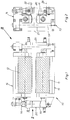
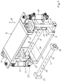
- the device 10 according to the invention for greasing workpieces in the form of strips or plates consists of a plurality of greasing rollers 11, 12 provided with fat-permeable material and aligned parallel to one another, each on one in a frame 13, 14 arranged hollow axis 15, 16 are mounted. Through these hollow axes 15, 16, the greasing agent is supplied to the interior of the greasing rollers 11, 12 via a plurality of closable, radial greasing agent outlet openings 18, which can be seen in FIG. 3 and are arranged in the longitudinal direction of the axis of symmetry 17.
- the lower and the upper frame 13, 14 are guided via linear guides 19 and pressure medium cylinders 20 arranged at both end regions in a manner that is exactly perpendicular to the central pass plane 21 of the workpiece, which is indicated by dash-dotted lines in FIG. 2, according to the double arrow 22 of FIG. 3.
- Both the pressure medium cylinders 20 and the ball guides 19 are arranged diagonally at the end regions of the lower and the upper frame 13 and 14.
- each hollow axis 15, 16 is provided at both ends with a shaped piece 23, 24 which can be inserted in a form-fitting manner in a correspondingly configured recess 25, 26 in the lower and in the upper frame 13, 14 and by means of it one generally designated 27 Locking device is releasably supported.
- the hollow axis 15 in the lower and also the hollow axis 16 in the upper frame 13, 14 are opposite to the conveying direction according to the arrow 28 in an insertion plane 29, 30 running parallel to the through plane 21 of the workpiece (not the board) (not shown) (see dash-dotted lines in Fig. 2) in the corresponding recesses 25, 26 can be used.
- the fittings 23, 24 in the lower and upper frame 13, 14 are cuboid. However, they can also have a cube shape. Furthermore, it is possible to form the shaped pieces 23, 24 and the corresponding recesses 25, 26 in the lower and upper frames 13, 14 at one end in a semicircular shape and to provide them with continuously adjoining, mutually parallel, flat surfaces. Such a design is indicated by dash-dotted lines in FIG. 3 in the left half.
- the locking device 27 of FIG. 3 consists of two screws 31, 32 which pass through the lower frame 13 and which can be provided with an external or internal hexagon head or also with a slotted head. With their external thread 33, the two screws 31, 32 engage in a corresponding internal thread 34 of the bores 35 in the lower and upper frame 13, 14 and clamp the shaped piece 23 on its lower surface 38.
- the screws 31, 32 consist of hollow screws with a ball 36 under the pretension of a spring, not shown, which engages in the locking position in a dome 37 provided in the shaped piece 23.
- the bias of the spring is advantageously dimensioned so large that automatic loosening of the hollow screws 31, 32 under the influence of all conceivable external forces, including vibrational forces, is excluded.
- the invention also allows the screws 31, 32 to be designed as full screws, secured at their heads with spring washers against unintentional rotation and provided at their free end with a cutting ring or a centering cone which, in the locking position, fits into a fitting 23, 24
- the hollow axles 15, 16 with their greasing rollers 11, 12 can also be used by technically untrained persons only in a single installation position and thus correctly in the corresponding recesses 25, 26.
- the hollow axes 15, 16 are connected in a rotationally fixed manner to the shaped pieces 23, 24.
Landscapes
- Engineering & Computer Science (AREA)
- Mechanical Engineering (AREA)
- Rollers For Roller Conveyors For Transfer (AREA)
- Bending Of Plates, Rods, And Pipes (AREA)
- Clamps And Clips (AREA)
- Processing And Handling Of Plastics And Other Materials For Molding In General (AREA)
- Press Drives And Press Lines (AREA)
Applications Claiming Priority (2)
| Application Number | Priority Date | Filing Date | Title |
|---|---|---|---|
| DE4332818 | 1993-09-28 | ||
| DE4332818A DE4332818A1 (de) | 1993-09-28 | 1993-09-28 | Vorrichtung zum Befetten von Werkstücken in Band- oder Platinenform |
Publications (2)
| Publication Number | Publication Date |
|---|---|
| EP0657227A1 true EP0657227A1 (fr) | 1995-06-14 |
| EP0657227B1 EP0657227B1 (fr) | 1998-11-11 |
Family
ID=6498720
Family Applications (1)
| Application Number | Title | Priority Date | Filing Date |
|---|---|---|---|
| EP94114126A Expired - Lifetime EP0657227B1 (fr) | 1993-09-28 | 1994-09-08 | Dispositif pour le graissage de pièces en forme de bandes ou de plaques |
Country Status (5)
| Country | Link |
|---|---|
| EP (1) | EP0657227B1 (fr) |
| AT (1) | ATE173184T1 (fr) |
| DE (2) | DE4332818A1 (fr) |
| DK (1) | DK0657227T3 (fr) |
| ES (1) | ES2126033T3 (fr) |
Cited By (2)
| Publication number | Priority date | Publication date | Assignee | Title |
|---|---|---|---|---|
| CN102673315A (zh) * | 2012-05-17 | 2012-09-19 | 常德占 | 一种具有润滑装置的钢板底座 |
| CN111822267A (zh) * | 2020-06-20 | 2020-10-27 | 科顺防水科技股份有限公司 | 一种防水卷材沥青涂覆上料设备 |
Families Citing this family (2)
| Publication number | Priority date | Publication date | Assignee | Title |
|---|---|---|---|---|
| DE4436848C2 (de) * | 1993-09-28 | 2001-11-08 | Raziol Zibulla & Sohn Gmbh | Vorrichtung zum Auftrag von flüssigen Medien, insbesondere von Befettungsmitteln, auf Werkstücke in Band- oder Platinenform |
| CN105864615A (zh) * | 2016-06-03 | 2016-08-17 | 海宁亚太化纤有限公司 | 一种纺纱机械自动润滑设备 |
Citations (6)
| Publication number | Priority date | Publication date | Assignee | Title |
|---|---|---|---|---|
| DE2716054A1 (de) * | 1977-04-09 | 1978-10-19 | Wilhelm Helmes | Vorrichtung zum befeuchten eines bandes mit schmierfluessigkeit vor dem loch-stanzen |
| SU633646A1 (ru) * | 1976-03-01 | 1978-11-25 | Новосибирское Отделение Всесоюзного Государственного Научно-Исследовательского И Проектного Институт Вниипроектэлектромонтаж | Устройство дл смазки полосового и ленточного материала |
| JPS5830366A (ja) * | 1981-08-19 | 1983-02-22 | Junichiro Takeda | 液体等の塗布方法および装置 |
| JPS5897405A (ja) * | 1981-12-03 | 1983-06-09 | Ishikawajima Harima Heavy Ind Co Ltd | 圧延機 |
| DE3507846C1 (de) * | 1985-03-06 | 1986-08-14 | Zibulla & Sohn GmbH Raziol Schmierungstechnik, 5860 Iserlohn | Vorrichtung zum Befetten von Werkstücken bei der spanlosen Umformung und beim Walzen, insbesondere Rollenbandöler |
| FR2674150A1 (fr) * | 1991-03-18 | 1992-09-25 | Vallet Gerard | Installation pour la lubrification de toles pour l'emboutissage. |
Family Cites Families (3)
| Publication number | Priority date | Publication date | Assignee | Title |
|---|---|---|---|---|
| DE2004706A1 (de) * | 1970-02-03 | 1971-08-26 | Goetzewerke Friedrich Goetze Ag, 5673 Burscheid | Vorrichtung zum gleichmaßigen Auftragen von Flüssigkeiten auf Werkstoffbahnen |
| DE7538002U (de) * | 1975-11-28 | 1976-04-22 | Horst Kirchner Maschinenbau, 7081 Essingen | Auftragmaschine zum auftragen zaehfluessiger medien, wie leim, lack ect. in form eines filmes auf ebene werkstueckflaechen |
| DE9304899U1 (de) * | 1993-03-31 | 1993-06-17 | Zibulla & Sohn GmbH Raziol-Schmierungstechnik, 5860 Iserlohn | Vorrichtung zum Befetten von Werkstücken in Band- oder Platinenform |
-
1993
- 1993-09-28 DE DE4332818A patent/DE4332818A1/de not_active Withdrawn
-
1994
- 1994-09-08 EP EP94114126A patent/EP0657227B1/fr not_active Expired - Lifetime
- 1994-09-08 DK DK94114126T patent/DK0657227T3/da active
- 1994-09-08 ES ES94114126T patent/ES2126033T3/es not_active Expired - Lifetime
- 1994-09-08 AT AT94114126T patent/ATE173184T1/de not_active IP Right Cessation
- 1994-09-08 DE DE59407278T patent/DE59407278D1/de not_active Expired - Lifetime
Patent Citations (6)
| Publication number | Priority date | Publication date | Assignee | Title |
|---|---|---|---|---|
| SU633646A1 (ru) * | 1976-03-01 | 1978-11-25 | Новосибирское Отделение Всесоюзного Государственного Научно-Исследовательского И Проектного Институт Вниипроектэлектромонтаж | Устройство дл смазки полосового и ленточного материала |
| DE2716054A1 (de) * | 1977-04-09 | 1978-10-19 | Wilhelm Helmes | Vorrichtung zum befeuchten eines bandes mit schmierfluessigkeit vor dem loch-stanzen |
| JPS5830366A (ja) * | 1981-08-19 | 1983-02-22 | Junichiro Takeda | 液体等の塗布方法および装置 |
| JPS5897405A (ja) * | 1981-12-03 | 1983-06-09 | Ishikawajima Harima Heavy Ind Co Ltd | 圧延機 |
| DE3507846C1 (de) * | 1985-03-06 | 1986-08-14 | Zibulla & Sohn GmbH Raziol Schmierungstechnik, 5860 Iserlohn | Vorrichtung zum Befetten von Werkstücken bei der spanlosen Umformung und beim Walzen, insbesondere Rollenbandöler |
| FR2674150A1 (fr) * | 1991-03-18 | 1992-09-25 | Vallet Gerard | Installation pour la lubrification de toles pour l'emboutissage. |
Non-Patent Citations (3)
| Title |
|---|
| PATENT ABSTRACTS OF JAPAN vol. 7, no. 108 (C - 165) 11 May 1983 (1983-05-11) * |
| PATENT ABSTRACTS OF JAPAN vol. 7, no. 197 (M - 239) 27 August 1983 (1983-08-27) * |
| SOVIET INVENTIONS ILLUSTRATED Section Ch Week B35, 10 October 1979 Derwent World Patents Index; Class M21, AN 64292B/35 * |
Cited By (3)
| Publication number | Priority date | Publication date | Assignee | Title |
|---|---|---|---|---|
| CN102673315A (zh) * | 2012-05-17 | 2012-09-19 | 常德占 | 一种具有润滑装置的钢板底座 |
| CN111822267A (zh) * | 2020-06-20 | 2020-10-27 | 科顺防水科技股份有限公司 | 一种防水卷材沥青涂覆上料设备 |
| CN111822267B (zh) * | 2020-06-20 | 2021-09-07 | 科顺防水科技股份有限公司 | 一种防水卷材沥青涂覆上料设备 |
Also Published As
| Publication number | Publication date |
|---|---|
| DK0657227T3 (da) | 1999-07-26 |
| DE4332818A1 (de) | 1995-03-30 |
| DE59407278D1 (de) | 1998-12-17 |
| ES2126033T3 (es) | 1999-03-16 |
| EP0657227B1 (fr) | 1998-11-11 |
| ATE173184T1 (de) | 1998-11-15 |
Similar Documents
| Publication | Publication Date | Title |
|---|---|---|
| DE2746921C3 (de) | Vorrichtung und Verfahren zur Herstellung von Verbindungen in und zur Prüfung von pneumatischen und hydraulischen Systemen | |
| DE19636375A1 (de) | Schnellverschluß für eine Palette unter Späneflug | |
| DE2855906A1 (de) | Spritzvorrichtung | |
| DE3136440A1 (de) | Spannvorrichtung zum spannen von werkzeugen | |
| EP0657227A1 (fr) | Dispositif pour le graissage de pièces en forme de bandes ou de plaques | |
| DE2857655C2 (de) | Vorrichtung zum Aufspannen von Wirkstücken auf einem Werkzeugmaschinentisch | |
| DE1511000B2 (de) | Offenendspinnmaschine | |
| DE3507846C1 (de) | Vorrichtung zum Befetten von Werkstücken bei der spanlosen Umformung und beim Walzen, insbesondere Rollenbandöler | |
| EP1163973A2 (fr) | Table pour une machine d'usinage | |
| DE3606147C1 (de) | Vorrichtung zur Aufnahme von scherenartig zusammenwirkenden,kreisfoermigen Schneidwerkzeugen | |
| EP2213414A2 (fr) | Meuleuse large | |
| DE3123291C2 (de) | Rollenbett an einer kontinuierlich arbeitenden Presse | |
| DE3511580C2 (fr) | ||
| DE102020120260A1 (de) | Werkzeugmaschinenhand | |
| DE9314505U1 (de) | Vorrichtung zum Befetten von Werkstücken in Band- oder Platinenform | |
| DE3742953C2 (fr) | ||
| EP0059448B1 (fr) | Dispositif de changement d'outils pour machine à travailler le bois | |
| EP0168792B1 (fr) | Plaque d'échange à chariots porte-outil pour une presse automatique à estamper et cintrer | |
| EP0688611B1 (fr) | Dispositif de graissage de plaques ou de bandes, comprenant des rouleaux de graissage rapidement interchangeables | |
| WO2022084196A1 (fr) | Système de rampe de pulvérisation modulaire pour refroidir et/ou lubrifier sélectivement des cylindres | |
| DE8506390U1 (de) | Vorrichtung zum Befetten von Werkstücken bei der spanlosen Umformung und beim Walzen, insbesondere Rollenbandöler | |
| DE69618346T2 (de) | Modulare prägevorrichtung für nahrungsmittel oder dgl. | |
| DE4228007A1 (de) | Honkopf mit spiralvorschub | |
| DE1527981C (de) | Profilwalzmaschine | |
| DE4436848C2 (de) | Vorrichtung zum Auftrag von flüssigen Medien, insbesondere von Befettungsmitteln, auf Werkstücke in Band- oder Platinenform |
Legal Events
| Date | Code | Title | Description |
|---|---|---|---|
| PUAI | Public reference made under article 153(3) epc to a published international application that has entered the european phase |
Free format text: ORIGINAL CODE: 0009012 |
|
| AK | Designated contracting states |
Kind code of ref document: A1 Designated state(s): AT CH DE DK ES FR GB IT LI NL PT SE |
|
| 17P | Request for examination filed |
Effective date: 19950513 |
|
| 17Q | First examination report despatched |
Effective date: 19961213 |
|
| GRAG | Despatch of communication of intention to grant |
Free format text: ORIGINAL CODE: EPIDOS AGRA |
|
| GRAG | Despatch of communication of intention to grant |
Free format text: ORIGINAL CODE: EPIDOS AGRA |
|
| GRAH | Despatch of communication of intention to grant a patent |
Free format text: ORIGINAL CODE: EPIDOS IGRA |
|
| GRAH | Despatch of communication of intention to grant a patent |
Free format text: ORIGINAL CODE: EPIDOS IGRA |
|
| ITF | It: translation for a ep patent filed | ||
| GRAA | (expected) grant |
Free format text: ORIGINAL CODE: 0009210 |
|
| AK | Designated contracting states |
Kind code of ref document: B1 Designated state(s): AT CH DE DK ES FR GB IT LI NL PT SE |
|
| REF | Corresponds to: |
Ref document number: 173184 Country of ref document: AT Date of ref document: 19981115 Kind code of ref document: T |
|
| REG | Reference to a national code |
Ref country code: CH Ref legal event code: EP |
|
| GBT | Gb: translation of ep patent filed (gb section 77(6)(a)/1977) |
Effective date: 19981112 |
|
| REG | Reference to a national code |
Ref country code: CH Ref legal event code: NV Representative=s name: MOINAS SAVOYE & CRONIN |
|
| REF | Corresponds to: |
Ref document number: 59407278 Country of ref document: DE Date of ref document: 19981217 |
|
| ET | Fr: translation filed | ||
| REG | Reference to a national code |
Ref country code: PT Ref legal event code: SC4A Free format text: AVAILABILITY OF NATIONAL TRANSLATION Effective date: 19981112 |
|
| REG | Reference to a national code |
Ref country code: ES Ref legal event code: FG2A Ref document number: 2126033 Country of ref document: ES Kind code of ref document: T3 |
|
| REG | Reference to a national code |
Ref country code: DK Ref legal event code: T3 |
|
| PLBE | No opposition filed within time limit |
Free format text: ORIGINAL CODE: 0009261 |
|
| STAA | Information on the status of an ep patent application or granted ep patent |
Free format text: STATUS: NO OPPOSITION FILED WITHIN TIME LIMIT |
|
| 26N | No opposition filed | ||
| PGFP | Annual fee paid to national office [announced via postgrant information from national office to epo] |
Ref country code: SE Payment date: 20010821 Year of fee payment: 8 |
|
| PGFP | Annual fee paid to national office [announced via postgrant information from national office to epo] |
Ref country code: PT Payment date: 20010830 Year of fee payment: 8 Ref country code: GB Payment date: 20010830 Year of fee payment: 8 |
|
| PGFP | Annual fee paid to national office [announced via postgrant information from national office to epo] |
Ref country code: DK Payment date: 20010921 Year of fee payment: 8 |
|
| PGFP | Annual fee paid to national office [announced via postgrant information from national office to epo] |
Ref country code: AT Payment date: 20010925 Year of fee payment: 8 |
|
| PGFP | Annual fee paid to national office [announced via postgrant information from national office to epo] |
Ref country code: ES Payment date: 20010926 Year of fee payment: 8 |
|
| PGFP | Annual fee paid to national office [announced via postgrant information from national office to epo] |
Ref country code: FR Payment date: 20010927 Year of fee payment: 8 |
|
| PGFP | Annual fee paid to national office [announced via postgrant information from national office to epo] |
Ref country code: CH Payment date: 20010928 Year of fee payment: 8 |
|
| PGFP | Annual fee paid to national office [announced via postgrant information from national office to epo] |
Ref country code: NL Payment date: 20010930 Year of fee payment: 8 |
|
| REG | Reference to a national code |
Ref country code: GB Ref legal event code: IF02 |
|
| PG25 | Lapsed in a contracting state [announced via postgrant information from national office to epo] |
Ref country code: GB Free format text: LAPSE BECAUSE OF NON-PAYMENT OF DUE FEES Effective date: 20020908 Ref country code: AT Free format text: LAPSE BECAUSE OF NON-PAYMENT OF DUE FEES Effective date: 20020908 |
|
| PG25 | Lapsed in a contracting state [announced via postgrant information from national office to epo] |
Ref country code: SE Free format text: LAPSE BECAUSE OF NON-PAYMENT OF DUE FEES Effective date: 20020909 Ref country code: ES Free format text: LAPSE BECAUSE OF NON-PAYMENT OF DUE FEES Effective date: 20020909 |
|
| PG25 | Lapsed in a contracting state [announced via postgrant information from national office to epo] |
Ref country code: LI Free format text: LAPSE BECAUSE OF NON-PAYMENT OF DUE FEES Effective date: 20020930 Ref country code: DK Free format text: LAPSE BECAUSE OF NON-PAYMENT OF DUE FEES Effective date: 20020930 Ref country code: CH Free format text: LAPSE BECAUSE OF NON-PAYMENT OF DUE FEES Effective date: 20020930 |
|
| PG25 | Lapsed in a contracting state [announced via postgrant information from national office to epo] |
Ref country code: PT Free format text: LAPSE BECAUSE OF NON-PAYMENT OF DUE FEES Effective date: 20030331 |
|
| PG25 | Lapsed in a contracting state [announced via postgrant information from national office to epo] |
Ref country code: NL Free format text: LAPSE BECAUSE OF NON-PAYMENT OF DUE FEES Effective date: 20030401 |
|
| GBPC | Gb: european patent ceased through non-payment of renewal fee |
Effective date: 20020908 |
|
| REG | Reference to a national code |
Ref country code: DK Ref legal event code: EBP |
|
| EUG | Se: european patent has lapsed | ||
| REG | Reference to a national code |
Ref country code: CH Ref legal event code: PL |
|
| PG25 | Lapsed in a contracting state [announced via postgrant information from national office to epo] |
Ref country code: FR Free format text: LAPSE BECAUSE OF NON-PAYMENT OF DUE FEES Effective date: 20030603 |
|
| REG | Reference to a national code |
Ref country code: PT Ref legal event code: MM4A Free format text: LAPSE DUE TO NON-PAYMENT OF FEES Effective date: 20030331 |
|
| REG | Reference to a national code |
Ref country code: FR Ref legal event code: ST |
|
| REG | Reference to a national code |
Ref country code: ES Ref legal event code: FD2A Effective date: 20031011 |
|
| PG25 | Lapsed in a contracting state [announced via postgrant information from national office to epo] |
Ref country code: IT Free format text: LAPSE BECAUSE OF NON-PAYMENT OF DUE FEES Effective date: 20050908 |
|
| PGFP | Annual fee paid to national office [announced via postgrant information from national office to epo] |
Ref country code: DE Payment date: 20130829 Year of fee payment: 20 |
|
| REG | Reference to a national code |
Ref country code: DE Ref legal event code: R071 Ref document number: 59407278 Country of ref document: DE |
|
| PG25 | Lapsed in a contracting state [announced via postgrant information from national office to epo] |
Ref country code: DE Free format text: LAPSE BECAUSE OF EXPIRATION OF PROTECTION Effective date: 20140909 |