EP0657245A1 - Vorrichtung zur Überwachen von Werkzeugbruchen oder zur Ermittelung der Anwesenheit eines Werkzeuges mittels eines Fluidstrahles - Google Patents
Vorrichtung zur Überwachen von Werkzeugbruchen oder zur Ermittelung der Anwesenheit eines Werkzeuges mittels eines Fluidstrahles Download PDFInfo
- Publication number
- EP0657245A1 EP0657245A1 EP94810699A EP94810699A EP0657245A1 EP 0657245 A1 EP0657245 A1 EP 0657245A1 EP 94810699 A EP94810699 A EP 94810699A EP 94810699 A EP94810699 A EP 94810699A EP 0657245 A1 EP0657245 A1 EP 0657245A1
- Authority
- EP
- European Patent Office
- Prior art keywords
- jet
- liquid
- sensor
- pressure
- signal
- Prior art date
- Legal status (The legal status is an assumption and is not a legal conclusion. Google has not performed a legal analysis and makes no representation as to the accuracy of the status listed.)
- Withdrawn
Links
- 239000007788 liquid Substances 0.000 claims description 22
- 238000001514 detection method Methods 0.000 claims description 3
- 230000005355 Hall effect Effects 0.000 claims description 2
- 230000000694 effects Effects 0.000 claims description 2
- 239000000696 magnetic material Substances 0.000 claims 1
- 239000012528 membrane Substances 0.000 claims 1
- 238000005086 pumping Methods 0.000 claims 1
- 230000035945 sensitivity Effects 0.000 claims 1
- 238000003754 machining Methods 0.000 abstract description 3
- 239000012530 fluid Substances 0.000 abstract 4
- 239000002173 cutting fluid Substances 0.000 abstract 1
- 238000012544 monitoring process Methods 0.000 abstract 1
- 230000002950 deficient Effects 0.000 description 2
- 230000003071 parasitic effect Effects 0.000 description 1
- 238000000926 separation method Methods 0.000 description 1
Images

Classifications
-
- B—PERFORMING OPERATIONS; TRANSPORTING
- B23—MACHINE TOOLS; METAL-WORKING NOT OTHERWISE PROVIDED FOR
- B23Q—DETAILS, COMPONENTS, OR ACCESSORIES FOR MACHINE TOOLS, e.g. ARRANGEMENTS FOR COPYING OR CONTROLLING; MACHINE TOOLS IN GENERAL CHARACTERISED BY THE CONSTRUCTION OF PARTICULAR DETAILS OR COMPONENTS; COMBINATIONS OR ASSOCIATIONS OF METAL-WORKING MACHINES, NOT DIRECTED TO A PARTICULAR RESULT
- B23Q17/00—Arrangements for observing, indicating or measuring on machine tools
- B23Q17/09—Arrangements for observing, indicating or measuring on machine tools for indicating or measuring cutting pressure or for determining cutting-tool condition, e.g. cutting ability, load on tool
- B23Q17/0904—Arrangements for observing, indicating or measuring on machine tools for indicating or measuring cutting pressure or for determining cutting-tool condition, e.g. cutting ability, load on tool before or after machining
- B23Q17/0909—Detection of broken tools
Definitions
- the object of the present invention is to detect breakage or the presence of the tool in an environment affected by splashes of cutting liquid or shavings. This detection is obtained by interrupting a jet of liquid whose tool is an obstacle, on the other hand if the tool is broken or not present the liquid jet is not interrupted, and this can be detected.
- Figure 1 is a schematic view of the essential elements of an apparatus according to the invention.
- the device consists of four very distinct elements, a double piston (2) to create sufficient pressure to obtain a jet of liquid via a nozzle (9), the jet of which strikes a sensor (10) whose the function is to transform the presence or not of the jet of liquid into an electrical signal, this signal will be analyzed by an electronic circuit (fig. 2), the output signal of which can be used to control a machine.
- the double piston (fig.) to create sufficient pressure to obtain a jet of liquid via a nozzle (9), the jet of which strikes a sensor (10) whose the function is to transform the presence or not of the jet of liquid into an electrical signal, this signal will be analyzed by an electronic circuit (fig. 2), the output signal of which can be used to control a machine.
- the double piston (fig. 1) to create sufficient pressure to obtain a jet of liquid via a nozzle (9), the jet of which strikes a sensor (10) whose the function is to transform the presence or not of the jet of liquid into an electrical signal, this signal will be analyzed by an electronic circuit (fig. 2), the
- the two flanges (6) are connected externally (13) to each other which has the effect of always having liquid under pressure through the nozzle (9), despite the inversion of the double piston (1) .
- the reversal control is provided by a Hall effect sensor (8) in each flange (6), as well as a magnet (10) on each end of the double piston.
- the outlet (17) is connected to an electrovalve (14) which has the function of interrupting and letting the pressure pass alternately several times per seconds, therefore we have a jet of fractionated liquid (12), which causes a pressure difference on the sensor (10) with each fraction of the liquid jet (12) in addition to the fact that the frequency is controlled by an electronic oscillator which controls the solenoid valve (14 ), a circuit electronic discriminator analyzes if the signal from the sensor (10) is in phase with the oscillator this function is intended to prevent parasitic jets generating an erroneous signal.
- the nozzle (9) has the function of creating a jet of concentric liquid the diameter of which remains constant over a greater distance than the tool holder, the diameter of the orifice of the nozzle can vary depending on the tool to be detected.
- a timer which is activated at each reversal the purpose of the piston is to make sure that the nozzle is not blocked or that the piston does not work, because if there is no reversal after a certain period of time the timer will give a signal on the optocoupler which will cause the same signal as the broken tool.
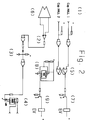
- the electronic circuit consists of an amplifier (2) whose input is connected to the sensor (1) and the output to an optocoupler (4) by via an RC circuit (3) the output of the optocoupler (4) can be used to control the machine stop.
- the Flip-Flop (5) has the function of memorizing the signal of each Hall sensor (6) and to control via the transistor (7) the solenoid valve which distributes in each chamber to obtain an alternating movement of the double piston.
- the square signal generator (8) ensures the control via the transistor (9), the solenoid valve for intermittent shutdown of the liquid jet.
Landscapes
- Engineering & Computer Science (AREA)
- Mechanical Engineering (AREA)
- Fluid-Pressure Circuits (AREA)
Applications Claiming Priority (2)
| Application Number | Priority Date | Filing Date | Title |
|---|---|---|---|
| CH363493 | 1993-12-07 | ||
| CH3634/93 | 1993-12-07 |
Publications (1)
| Publication Number | Publication Date |
|---|---|
| EP0657245A1 true EP0657245A1 (de) | 1995-06-14 |
Family
ID=4260203
Family Applications (1)
| Application Number | Title | Priority Date | Filing Date |
|---|---|---|---|
| EP94810699A Withdrawn EP0657245A1 (de) | 1993-12-07 | 1994-12-06 | Vorrichtung zur Überwachen von Werkzeugbruchen oder zur Ermittelung der Anwesenheit eines Werkzeuges mittels eines Fluidstrahles |
Country Status (1)
| Country | Link |
|---|---|
| EP (1) | EP0657245A1 (de) |
Cited By (5)
| Publication number | Priority date | Publication date | Assignee | Title |
|---|---|---|---|---|
| DE10240764A1 (de) * | 2002-08-30 | 2004-03-18 | Nordmann, Klaus, Dr.-Ing. | Staudrucksensor |
| US6823270B1 (en) * | 2001-06-20 | 2004-11-23 | Curtis Roys | Fluid flow monitoring system |
| DE102008009570A1 (de) | 2008-02-16 | 2009-08-20 | Nordmann, Klaus, Dr.-Ing. | Verfahren zur Werkzeugbruchkontrolle mittels der Turbulenzen eines Kühlschmierstoff- oder Druckluftstrahls |
| US7720574B1 (en) | 2001-06-20 | 2010-05-18 | Curtis Roys | Fluid flow monitor and control system |
| CN103600265A (zh) * | 2013-08-02 | 2014-02-26 | 浙江吉利汽车研究院有限公司 | 一种刀具检测装置及其检测方法 |
Citations (6)
| Publication number | Priority date | Publication date | Assignee | Title |
|---|---|---|---|---|
| FR1344965A (fr) * | 1962-09-04 | 1963-12-06 | Ceske Zd Y Motocyklove Narodni | Dispositif de contrôle et surveillance des extrêmités d'outils, notamment forets,tarauds |
| US3609053A (en) * | 1969-04-29 | 1971-09-28 | Ite Imperial Corp | Broken tool detector |
| DE3018123A1 (de) * | 1980-05-12 | 1981-11-19 | Samson Ag, 6000 Frankfurt | Vorrichtung zur ueberwachung der funktionsfaehigkeit eines bohrwerkzeugs oder sonstigen beweglichen organs |
| DE3021026A1 (de) * | 1980-06-03 | 1981-12-10 | Samson Ag, 6000 Frankfurt | Vorrichtung zur ueberwachung der funktionsfaehigkeit eines bohrwerkzeugs oder sonstigen beweglichen organs |
| JPS5713281A (en) * | 1980-06-28 | 1982-01-23 | Far East Eng Kk | Reciprocating pump |
| EP0538236A1 (de) * | 1991-09-30 | 1993-04-21 | Hoerbiger Ventilwerke Aktiengesellschaft | Piezo-Ventil |
-
1994
- 1994-12-06 EP EP94810699A patent/EP0657245A1/de not_active Withdrawn
Patent Citations (6)
| Publication number | Priority date | Publication date | Assignee | Title |
|---|---|---|---|---|
| FR1344965A (fr) * | 1962-09-04 | 1963-12-06 | Ceske Zd Y Motocyklove Narodni | Dispositif de contrôle et surveillance des extrêmités d'outils, notamment forets,tarauds |
| US3609053A (en) * | 1969-04-29 | 1971-09-28 | Ite Imperial Corp | Broken tool detector |
| DE3018123A1 (de) * | 1980-05-12 | 1981-11-19 | Samson Ag, 6000 Frankfurt | Vorrichtung zur ueberwachung der funktionsfaehigkeit eines bohrwerkzeugs oder sonstigen beweglichen organs |
| DE3021026A1 (de) * | 1980-06-03 | 1981-12-10 | Samson Ag, 6000 Frankfurt | Vorrichtung zur ueberwachung der funktionsfaehigkeit eines bohrwerkzeugs oder sonstigen beweglichen organs |
| JPS5713281A (en) * | 1980-06-28 | 1982-01-23 | Far East Eng Kk | Reciprocating pump |
| EP0538236A1 (de) * | 1991-09-30 | 1993-04-21 | Hoerbiger Ventilwerke Aktiengesellschaft | Piezo-Ventil |
Non-Patent Citations (1)
| Title |
|---|
| PATENT ABSTRACTS OF JAPAN vol. 6, no. 74 (M - 127) 11 May 1982 (1982-05-11) * |
Cited By (9)
| Publication number | Priority date | Publication date | Assignee | Title |
|---|---|---|---|---|
| US6823270B1 (en) * | 2001-06-20 | 2004-11-23 | Curtis Roys | Fluid flow monitoring system |
| US7379827B1 (en) | 2001-06-20 | 2008-05-27 | Curtis Roys | Fluid flow monitoring system |
| US7720574B1 (en) | 2001-06-20 | 2010-05-18 | Curtis Roys | Fluid flow monitor and control system |
| US7970558B1 (en) | 2001-06-20 | 2011-06-28 | Coltec Industrial Products Llc | Fluid flow monitor and control system |
| US8561477B2 (en) | 2001-06-20 | 2013-10-22 | Coltec Industrial Products Llc | Fluid flow monitor and control system |
| DE10240764A1 (de) * | 2002-08-30 | 2004-03-18 | Nordmann, Klaus, Dr.-Ing. | Staudrucksensor |
| DE10240764B4 (de) * | 2002-08-30 | 2005-07-28 | Nordmann, Klaus, Dr.-Ing. | Vorrichtung zum Erfassen der Position und der bruchbedingten Verkürzung eines Werkzeugs oder Werkstückes in einer Werkzeugmaschine |
| DE102008009570A1 (de) | 2008-02-16 | 2009-08-20 | Nordmann, Klaus, Dr.-Ing. | Verfahren zur Werkzeugbruchkontrolle mittels der Turbulenzen eines Kühlschmierstoff- oder Druckluftstrahls |
| CN103600265A (zh) * | 2013-08-02 | 2014-02-26 | 浙江吉利汽车研究院有限公司 | 一种刀具检测装置及其检测方法 |
Similar Documents
| Publication | Publication Date | Title |
|---|---|---|
| JP4776141B2 (ja) | 噴霧ピストル | |
| US4846003A (en) | Acoustic impedance system for pipette tip detection | |
| US4487601A (en) | Bubble detector circuit with variable reference level | |
| CN1294676A (zh) | 一种用于分类流量细胞计数器的振动系统 | |
| EP0657245A1 (de) | Vorrichtung zur Überwachen von Werkzeugbruchen oder zur Ermittelung der Anwesenheit eines Werkzeuges mittels eines Fluidstrahles | |
| EP0853236A1 (de) | Flüssigkeitsdetektor | |
| US4909081A (en) | Systems for detecting magnetic particles in fluids | |
| US7463158B2 (en) | Acoustic particle alarm including particle sensor | |
| US5943294A (en) | Level detector for fluent material | |
| GB2236180A (en) | Detection of bubbles in flowing liquids | |
| US20010042407A1 (en) | Apparatus for detecting and measuring foam forming compounds in aqueous solutions | |
| KR19990036129A (ko) | 파이프내의 액체 특성 탐지 및 펌프 제어 방법 | |
| CA3024668C (en) | Centrifugal separator with a sensor device | |
| US7620505B2 (en) | Device for determining and/or monitoring the volume, and/or mass, flow rate of a medium | |
| FR2768941A1 (fr) | Dispositif contre le colmatage d'un filtre | |
| FR2623109A1 (fr) | Dispositif permettant la diffusion de produits fluides | |
| US4065675A (en) | Flow monitoring devices | |
| US6189547B1 (en) | Ultrasonic washing apparatus | |
| FR2459456A1 (fr) | Debitmetre a turbine | |
| FR2478255A1 (fr) | Dispositif de detection par ultrasons de fermeture d'un clapet | |
| US4550314A (en) | Meter monitor apparatus | |
| DE3810669C2 (de) | Vorrichtung zur Überwachung des Pegelstandes einer Flüssigkeit | |
| KR950008839A (ko) | 빨래 건조기의 필터막힘감지장치 | |
| EP0402656A2 (de) | Luftverschmutzungswarngerät | |
| EP0117195A1 (de) | Elektromagnetisches Ventil mit piezoelektrischer Betätigung |
Legal Events
| Date | Code | Title | Description |
|---|---|---|---|
| PUAI | Public reference made under article 153(3) epc to a published international application that has entered the european phase |
Free format text: ORIGINAL CODE: 0009012 |
|
| AK | Designated contracting states |
Kind code of ref document: A1 Designated state(s): CH DE ES FR LI |
|
| 17P | Request for examination filed |
Effective date: 19951121 |
|
| STAA | Information on the status of an ep patent application or granted ep patent |
Free format text: STATUS: THE APPLICATION IS DEEMED TO BE WITHDRAWN |
|
| 18D | Application deemed to be withdrawn |
Effective date: 19970701 |