EP0657256B1 - Vorrichtung zum Rillen eines Garantieverschlusses aus Kunststoff und Verfahren zum Einrichten derselben - Google Patents
Vorrichtung zum Rillen eines Garantieverschlusses aus Kunststoff und Verfahren zum Einrichten derselben Download PDFInfo
- Publication number
- EP0657256B1 EP0657256B1 EP94115819A EP94115819A EP0657256B1 EP 0657256 B1 EP0657256 B1 EP 0657256B1 EP 94115819 A EP94115819 A EP 94115819A EP 94115819 A EP94115819 A EP 94115819A EP 0657256 B1 EP0657256 B1 EP 0657256B1
- Authority
- EP
- European Patent Office
- Prior art keywords
- knife
- apparatus part
- holder
- closure
- arc
- Prior art date
- Legal status (The legal status is an assumption and is not a legal conclusion. Google has not performed a legal analysis and makes no representation as to the accuracy of the status listed.)
- Expired - Lifetime
Links
- 239000004033 plastic Substances 0.000 title claims abstract description 7
- 238000000034 method Methods 0.000 title claims description 16
- 238000005520 cutting process Methods 0.000 claims description 19
- 230000002093 peripheral effect Effects 0.000 claims description 6
- 230000000295 complement effect Effects 0.000 claims 1
- 238000010276 construction Methods 0.000 description 4
- 238000012423 maintenance Methods 0.000 description 3
- 230000001419 dependent effect Effects 0.000 description 2
- 230000000007 visual effect Effects 0.000 description 2
- 239000004743 Polypropylene Substances 0.000 description 1
- 239000011324 bead Substances 0.000 description 1
- 238000000748 compression moulding Methods 0.000 description 1
- 229910003460 diamond Inorganic materials 0.000 description 1
- 239000010432 diamond Substances 0.000 description 1
- 238000001746 injection moulding Methods 0.000 description 1
- 238000004519 manufacturing process Methods 0.000 description 1
- -1 polypropylene Polymers 0.000 description 1
- 229920001155 polypropylene Polymers 0.000 description 1
- 238000005096 rolling process Methods 0.000 description 1
Images


Classifications
-
- B—PERFORMING OPERATIONS; TRANSPORTING
- B26—HAND CUTTING TOOLS; CUTTING; SEVERING
- B26D—CUTTING; DETAILS COMMON TO MACHINES FOR PERFORATING, PUNCHING, CUTTING-OUT, STAMPING-OUT OR SEVERING
- B26D7/00—Details of apparatus for cutting, cutting-out, stamping-out, punching, perforating, or severing by means other than cutting
- B26D7/26—Means for mounting or adjusting the cutting member; Means for adjusting the stroke of the cutting member
- B26D7/2628—Means for adjusting the position of the cutting member
-
- B—PERFORMING OPERATIONS; TRANSPORTING
- B26—HAND CUTTING TOOLS; CUTTING; SEVERING
- B26D—CUTTING; DETAILS COMMON TO MACHINES FOR PERFORATING, PUNCHING, CUTTING-OUT, STAMPING-OUT OR SEVERING
- B26D3/00—Cutting work characterised by the nature of the cut made; Apparatus therefor
- B26D3/08—Making a superficial cut in the surface of the work without removal of material, e.g. scoring, incising
-
- B—PERFORMING OPERATIONS; TRANSPORTING
- B26—HAND CUTTING TOOLS; CUTTING; SEVERING
- B26D—CUTTING; DETAILS COMMON TO MACHINES FOR PERFORATING, PUNCHING, CUTTING-OUT, STAMPING-OUT OR SEVERING
- B26D7/00—Details of apparatus for cutting, cutting-out, stamping-out, punching, perforating, or severing by means other than cutting
- B26D7/01—Means for holding or positioning work
- B26D7/02—Means for holding or positioning work with clamping means
-
- B—PERFORMING OPERATIONS; TRANSPORTING
- B26—HAND CUTTING TOOLS; CUTTING; SEVERING
- B26F—PERFORATING; PUNCHING; CUTTING-OUT; STAMPING-OUT; SEVERING BY MEANS OTHER THAN CUTTING
- B26F2210/00—Perforating, punching, cutting-out, stamping-out, severing by means other than cutting of specific products
- B26F2210/04—Making plastic pilferproof screw caps by cutting a tamper ring
-
- Y—GENERAL TAGGING OF NEW TECHNOLOGICAL DEVELOPMENTS; GENERAL TAGGING OF CROSS-SECTIONAL TECHNOLOGIES SPANNING OVER SEVERAL SECTIONS OF THE IPC; TECHNICAL SUBJECTS COVERED BY FORMER USPC CROSS-REFERENCE ART COLLECTIONS [XRACs] AND DIGESTS
- Y10—TECHNICAL SUBJECTS COVERED BY FORMER USPC
- Y10T—TECHNICAL SUBJECTS COVERED BY FORMER US CLASSIFICATION
- Y10T82/00—Turning
- Y10T82/16—Severing or cut-off
- Y10T82/16016—Processes
-
- Y—GENERAL TAGGING OF NEW TECHNOLOGICAL DEVELOPMENTS; GENERAL TAGGING OF CROSS-SECTIONAL TECHNOLOGIES SPANNING OVER SEVERAL SECTIONS OF THE IPC; TECHNICAL SUBJECTS COVERED BY FORMER USPC CROSS-REFERENCE ART COLLECTIONS [XRACs] AND DIGESTS
- Y10—TECHNICAL SUBJECTS COVERED BY FORMER USPC
- Y10T—TECHNICAL SUBJECTS COVERED BY FORMER US CLASSIFICATION
- Y10T82/00—Turning
- Y10T82/16—Severing or cut-off
- Y10T82/16426—Infeed means
- Y10T82/16967—Infeed means with means to support and/or rotate work
-
- Y—GENERAL TAGGING OF NEW TECHNOLOGICAL DEVELOPMENTS; GENERAL TAGGING OF CROSS-SECTIONAL TECHNOLOGIES SPANNING OVER SEVERAL SECTIONS OF THE IPC; TECHNICAL SUBJECTS COVERED BY FORMER USPC CROSS-REFERENCE ART COLLECTIONS [XRACs] AND DIGESTS
- Y10—TECHNICAL SUBJECTS COVERED BY FORMER USPC
- Y10T—TECHNICAL SUBJECTS COVERED BY FORMER US CLASSIFICATION
- Y10T83/00—Cutting
- Y10T83/02—Other than completely through work thickness
- Y10T83/0207—Other than completely through work thickness or through work presented
- Y10T83/023—With infeeding of work
-
- Y—GENERAL TAGGING OF NEW TECHNOLOGICAL DEVELOPMENTS; GENERAL TAGGING OF CROSS-SECTIONAL TECHNOLOGIES SPANNING OVER SEVERAL SECTIONS OF THE IPC; TECHNICAL SUBJECTS COVERED BY FORMER USPC CROSS-REFERENCE ART COLLECTIONS [XRACs] AND DIGESTS
- Y10—TECHNICAL SUBJECTS COVERED BY FORMER USPC
- Y10T—TECHNICAL SUBJECTS COVERED BY FORMER US CLASSIFICATION
- Y10T83/00—Cutting
- Y10T83/02—Other than completely through work thickness
- Y10T83/0333—Scoring
- Y10T83/0341—Processes
-
- Y—GENERAL TAGGING OF NEW TECHNOLOGICAL DEVELOPMENTS; GENERAL TAGGING OF CROSS-SECTIONAL TECHNOLOGIES SPANNING OVER SEVERAL SECTIONS OF THE IPC; TECHNICAL SUBJECTS COVERED BY FORMER USPC CROSS-REFERENCE ART COLLECTIONS [XRACs] AND DIGESTS
- Y10—TECHNICAL SUBJECTS COVERED BY FORMER USPC
- Y10T—TECHNICAL SUBJECTS COVERED BY FORMER US CLASSIFICATION
- Y10T83/00—Cutting
- Y10T83/04—Processes
- Y10T83/0596—Cutting wall of hollow work
-
- Y—GENERAL TAGGING OF NEW TECHNOLOGICAL DEVELOPMENTS; GENERAL TAGGING OF CROSS-SECTIONAL TECHNOLOGIES SPANNING OVER SEVERAL SECTIONS OF THE IPC; TECHNICAL SUBJECTS COVERED BY FORMER USPC CROSS-REFERENCE ART COLLECTIONS [XRACs] AND DIGESTS
- Y10—TECHNICAL SUBJECTS COVERED BY FORMER USPC
- Y10T—TECHNICAL SUBJECTS COVERED BY FORMER US CLASSIFICATION
- Y10T83/00—Cutting
- Y10T83/849—With signal, scale, or indicator
- Y10T83/852—Responsive to force
-
- Y—GENERAL TAGGING OF NEW TECHNOLOGICAL DEVELOPMENTS; GENERAL TAGGING OF CROSS-SECTIONAL TECHNOLOGIES SPANNING OVER SEVERAL SECTIONS OF THE IPC; TECHNICAL SUBJECTS COVERED BY FORMER USPC CROSS-REFERENCE ART COLLECTIONS [XRACs] AND DIGESTS
- Y10—TECHNICAL SUBJECTS COVERED BY FORMER USPC
- Y10T—TECHNICAL SUBJECTS COVERED BY FORMER US CLASSIFICATION
- Y10T83/00—Cutting
- Y10T83/849—With signal, scale, or indicator
- Y10T83/853—Indicates tool position
- Y10T83/855—Relative to another element
- Y10T83/863—Adjustable guide for traversing tool; e.g., radial saw guide or miter saw guide
Definitions
- This invention relates to a method of preparing and to an apparatus for forming a circumferential score in a plastic closure according to the preambles of claims 1 and 6, respectively.
- Such scores are used to define a tamper indicating band on the closure connected to the peripheral skirt by a plurality of bridges. The bridges are broken when the closure is removed from a container.
- CA-A-1,161,611 shows scoring of bottle caps by conveying the caps with a turret along an arcuate knife.
- the knife is clamped in a knife holder which can be adjusted by adjusting means formed by a threaded rod with a knob thereon.
- tamper indicating closure includes molded circumferentially spaced bridges in order to define a tamper indicating band on the closure. Such construction requires costly more complex molds which also require maintenance. Typical patents showing such tamper indicating closures comprise US-A-4,613,052, 4,721,218, 4,801,031, 5,090,246 and 5,090,788.
- Another type of tamper indicating closure comprises utilizing an interrupted edged knife to produce bridges such as shown in US-A-4,322,009.
- a tamper indicating closure which comprises a base wall and a peripheral skirt having an internal thread adapted to engage the threads of a container wherein a tamper indicating band is provided on the skirt by a plurality of circumferentially spaced bridges.
- the band includes portions adapted to engage an annular bead on the container.
- the bridges are formed by using a primary knife having an interrupted cutting edge to produce a circumferential score in the side wall of the closure leaving spaced connectors or bridges.
- a secondary knife is used having a continuous uninterrupted cutting edge to provide a continuous external score line to provide an accurately dimensional radial thickness of the bridges.
- the closures engage the successive primary and secondary knives and are moved such that the closures roll relative to the knives.
- each arcuate knife is mounted directly onto the apparatus, and its radial position and concentricity are set while the knife is mounted on the apparatus, using adjusting micrometer screws, one at each end of the arcuate blade.
- Such an apparatus has the disadvantage of loss of machine productive time while the operator is setting blades. It is also difficult to maintain knife concentricity with the center of rotation of the apparatus. This requires operator skill in setting of the knives, and effective maintenance of the arcuate setting.
- the invention is based on the problem of setting knifes or blades without loss of machine production time.
- each knife blade is accurately set utilizing a remote setting fixture and the method of preparing it; wherein the setting fixture does not require the use of a dial indicator and, therefore, is not affected by the variability of the dial indicator setting and needs less skill in use; wherein the setting fixture cannot be over adjusted; and wherein the adjustment is less dependent on operator skill.
- a method and apparatus for scoring plastic tamper indicating closures to provide the tamper indicating band that is connected to the closure by bridges formed by scoring.
- the scoring is achieved by successively moving a rotating closure on rotating mandrel past a stationary primary knife blade having an arcuate concave interrupted cutting edge to form the bridges and then past a secondary knife blade having an arcuate concave uninterrupted cutting edge to accurately dimension the bridges.
- the method and apparatus provides for supporting each knife blade on a holder wherein the position of the blade can be set by setting the blade into a knife blade holder using a setting fixture remote from the apparatus, clamping the blade within the knife blade holder, transferring the holder to a machine mounting on the apparatus, then attaching the holder to the machine mounting without further adjustment, such that the arcuate knife blade is aligned such that the center of the radius of the arc of each arcuate knife blade is substantially coincident with the center of the apparatus.
- Each knife blade holder is preferably mounted on a slide on the rotary apparatus such that the arcuate edge can be finely adjusted so that the concave arc is parallel to the path of travel of the mandrels and at the required depth for the successive scoring.
- the method and apparatus includes:
- FIG. 1 is a fragmentary plan view of a rotary scoring apparatus embodying the invention.
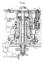
- FIG. 2 is a sectional view taken along the line 2-2 in FIG. 1, parts being broken away.
- FIG. 3 is a fragmentary partly diagrammatic plan view of a portion of the apparatus shown in FIG. 1.
- FIG. 4 is a fragmentary part sectional elevational view of a portion of the apparatus taken along the line 4-4 in FIG. 3.
- FIG. 5 is a fragmentary elevational view taken along the line 5-5 in FIG. 3.
- FIG. 6 is a fragmentary sectional view taken along the line 6-6 in FIG. 3.
- FIG. 7 is a partly diagrammatic plan view showing one of the knife blades having an interrupted cutting edge mounted on the apparatus.
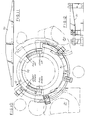
- FIG. 8 is a plan view of a setting fixture with the knife blade shown in FIG. 7 mounted thereon.
- FIG. 9 is a sectional view taken along the line 9-9 in FIG. 8.
- FIG. 10 is a partly diagrammatic view of the apparatus cams utilized in the rotary apparatus for moving the closures into each of the knife blades and raising and lowering the tooling as the apparatus rotates.
- FIG. 11 is a fragmentary elevational view of a portion of the cams on the apparatus.
- FIG. 12 is a fragmentary plan view of a portion of the apparatus.
- the method and apparatus embodying the invention includes a rotary scoring machine or apparatus 20 that has a base 21.
- a column 22 is mounted on the base 21 and a turret 23 is mounted for rotation on the column 22 by spaced bearings 24, 25.
- the turret 23 supports a plurality of sets of tooling including an upper tooling 26 and a lower tooling 27.
- the upper tooling 26 functions to hold a closure C in position on the lower tooling 27 so that it can be moved and rotated past successive arcuate knife blades, as presently described.
- Closures C are made of plastic, such as polypropylene, by injection molding or compression molding and comprise a base wall and peripheral skirt.
- the tamper indicating function is provided by a score line and is preferably of the type shown in US-A-5,090,788.
- Closures C are moved successively into the turret 23 and onto support pads of the lower tooling by a starwheel 30. Af ter the closures C are scored, they are removed from the turret by a starwheel 31 (FIG. 1).
- each closure C includes a base wall and a peripheral skirt and is moved past successive cutting knife blades 33, 34 mounted on holders, as presently described.
- the knife blade 33 has an interrupted concave arcuate cutting edge and the knife blade 34 has a continuous concave arcuate cutting edge such that as a closure C is moved by the turret and the closure is rotated into the successive knife blades, the primary knife blade 33 produces a circumferential score in the sidewall of the closure leaving spaced connectors or bridges and the secondary knife blade 34 provides a continuous external score line and an accurately dimensional radial thickness of the bridges, as more fully discussed in EP-A-0 621 475 A1.
- Each knife blade 33, 34 is in the form of a flat blade clamped in a knife blade holder 40 which is mounted on a linear machine slide 41 which is in turn mounted on the machine base 21 such that the linear slide 41 is radial to the rotation of a machine mounted turret (FIG. 6) .
- each set of upper tooling 26 on the turret 23 includes a mandrel 43 with its axis parallel to the axis of rotation of the turret 26.
- Each mandrel 43 is rotated past an arcuate fixed gear 44 as the turret is rotated and a pinion gear 45 on each mandrel 43 meshes with fixed gear 44 to rotate the mandrel.
- a closure C is carried on each mandrel 43 and is brought successively into tangential contact with the blades 33, 34 such that scoring takes place in the side wall or skirt of the closure C to delineate the band.
- the rotation of each closure C preferably is a substantially true rolling motion with each blade.
- Each arcuate blade 33, 34 is designed such that at the desired depth of cut, the blade cutting edge is concentric to the turret center of rotation.
- a blade setting fixture 60 enables the pre-setting of each arcuate blade 33, 34 in the holder 40 such that when transferred to the machine mounting the arcuate blade will be aligned such that both the center of the radius of the arc of the arcuate blade and the midpoint of said arc lies on a radial line from the center of the turret parallel to the linear adjustment of the machine slide on which it is mounted.
- a position can be established whereby the blade arc is concentric to the center of rotation of the turret.
- Each knife blade holder 40 includes knife blade holding plates 46a, 46b between which a knife blade 33 or 34 is clamped by headed screws 47.
- the knife blade has openings through which screws 47 extend.
- the plates 46a, 46b and knife blade holder further include openings 48, 49, 50 for engaging dowels 51 on the dovetail slide 52 on the base 21 of the apparatus (FIGS. 3, 4).
- Each knife blade 33, 34 is adjusted in a fixture 60 in a similar manner.
- the radial depth of scoring of each knife blade can be controlled by rotating a knob 54 on the slide in visual guidance by a visual dial indicator 59.
- This construction comprises a screw 55 on which knob 54 is mounted. Screw 55 is journalled on slide 52 and engages a nut 56 fixed on base 53.
- the blade setting fixture 60 includes a base 61, a pair of pilot holes 62 for the mounting of fixed cylindrical stops 63 in the form of rolls and a pair of cam shafts 64 supporting eccentric cams 65 connected to the shafts 64 by torque limiter knobs 66.
- the fixture includes a diamond shaped dowel 57 and a regular dowel 58 (to allow for pitch error) and securing screws (not shown) so as to replicate the machine mounting of the knife holder 40 on the base 61.
- the fixed stops 63 are machined to preset dimensions for each particular blade profile/cap diameter combination, and selected and fitted accordingly.
- a blade is secured snugly but free to move within the holding plates 46a, 46b and the assembly is mounted onto the setting fixture 60.
- the adjustment knobs 66 By carefully rotating the adjustment knobs 66, the blade is moved toward the fixed stops 63 until the blade cutting edge contacts the stops 63.
- the torque limiter knobs 66 slip, the final blade position is reached and the blade can be finally clamped between the holder plates 46a, 46b, by tightening screw 47.
- the blade arc will change for differing closure diameters, and within a limited range it is possible by geometry to ensure that the fixed stops 63 are designed such that a particular "zero" position of the slide as indicated by the digital indicator on the slide, would be the correct position for the desired depth of cut. For closure diameters outside this range, it may be necessary to establish a different slide position f or which the desired depth of cut would be theoretically correct in order that the blade projection from the blade holder is held to a practical minimum. However, due to variability in the parts, and the need to exactly control the depth of cut to ensure adequate band performance, it may be necessary to marginally deviate from this desired setting.
- the slide 52 provides this adjustment and as mentioned is equipped with a digital indicator 59 to provide accurate feedback on the radial adjustment. The resulting minimal blade arc eccentricity to the turret center of rotation is negligible in practice.
- Cams 70, 71 are provided for lifting and lowering the closure C on the lower tooling 27 into engagement with mandrel 43 by engaging rollers 72, 73, respectively, on an actuator 75 which supports a closure supporting pad 84.
- a cam roller 77 extends into a slot 78 on the turret 23 to guide the vertical movement of pad 84 (FIGS. 2, 10-12).
- each set of lower tooling 27 comprises a block 80 fixed on a shaft 81 slidable in upper and lower linear ball bearings 82, 83 and with antirotation means comprising the roller 77 on the block 80 operating in slot 78 on the turret 23.
- Block 80 supports spring loaded closure support pad 84.
- the tooling 27 is more readily accessible for changing the tooling.
Landscapes
- Forests & Forestry (AREA)
- Engineering & Computer Science (AREA)
- Mechanical Engineering (AREA)
- Life Sciences & Earth Sciences (AREA)
- Closures For Containers (AREA)
- Cartons (AREA)
- Casting Or Compression Moulding Of Plastics Or The Like (AREA)
- Details Of Cutting Devices (AREA)
- Conveying And Assembling Of Building Elements In Situ (AREA)
- Shaping Of Tube Ends By Bending Or Straightening (AREA)
- Lining Or Joining Of Plastics Or The Like (AREA)
- Earth Drilling (AREA)
- Heating, Cooling, Or Curing Plastics Or The Like In General (AREA)
- Closing Of Containers (AREA)
- Perforating, Stamping-Out Or Severing By Means Other Than Cutting (AREA)
Claims (11)
- Verfahren zum Einrichten einer Vorrichtung zur Erzeugung einer Umfangsrille in einem Garantieverschluß (C) aus Kunststoff mit einer Basiswandung und einer Umfangsringwandung, mit folgenden Merkmalen:ein drehbares Geräteteil (23) zum Verschieben des Verschlusses (C) auf einem Bogen um das Drehzentrum dieses Geräteteils entlang eines Ritzmessers;ein stationäres Geräteteil (21) umfassend:ein Messer (33, 34) mit mindestens einer bogenförmigen, konkaven Schneidkante, die im Hinblick auf Konzentrizität zum Drehzentrum des drehbaren Geräteteils ausgebildet ist, undeinen Messerhalter (40) mit einer Klemmeinrichtung (46a, 46b) zum Lösen und Festklemmen des Messers, um das Messer während des Ritzens des Verschlusses (C) stationär zu halten,wobei das Verfahren folgende Schritte aufweist:am Messerhalter (40) werden Festlegeeinrichtungen (50) vorgesehen;an dem stationären Geräteteil werden zweite Festlegeeinrichtungen (51) vorgesehen, die in die ersten Festlegeeinrichtungen (50) eingreifen;eine Montagevorrichtung (60) mit dritten Festlegeeinrichtungen (57, 58) zur Festlegung des Werkzeughalters (40) auf der Montageeinrichtung (60) durch Eingriff in die ersten Festlegeeinrichtung (50) weist im Abstand voneinander angeordnete Anschläge (63) auf, die einen Anlagebogen mit der bogenförmigen Schneidkante des Messers bestimmen, so daß sich der Bogen der Messerklinge in einer vorbestimmten Stellung relativ zum Halter (40) befindet, wenn die Schneidkante an den Anschlägen anliegt;das Messer (33, 34) wird in dem Messerhalter (40) positioniert;der Messerhalter (40) wird auf der Montagevorrichtung (60) positioniert;das Messer (33, 34) wird relativ zum Messerhalter (40) gegen die Anschläge (63) mit vorbestimmter Kraft verschoben;die Klemmeinrichtung (46a, 46b) wird zum Festziehen des Messers (33, 34) relativ zum Messerhalter (40) festgezogen;der Messerhalter (40) wird von der Montagevorrichtung (60) entfernt;der Messerhalter (40) wird auf dem stationären Geräteteil (21) positioniert, indem die ersten Festlegeeinrichtungen (50) des Messerhalters (40) zum Eingriff mit den zweiten Festlegeeinrichtungen (51) auf dem stationären Geräteteil (21) gebracht werden, so daß die bogenförmige Kante des Messers im richtigen Bogen positioniert wird und der Krümmungsradius des Messerbogens im wesentlichen dem Drehzentrum des drehbaren Geräteteils (23) entspricht und auf einer radialen Linie des drehbaren Geräteteils liegt.
- Verfahren nach Anspruch 1,
dadurch gekennzeichnet, daß zur Schaffung der Festlegeeinrichtungen für den Messerhalter (40) komplementäre Zapfen (51; 57, 58) und Öffnungen (50) vorgesehen werden. - Verfahren nach Anspruch 1,
dadurch gekennzeichnet, daß zur Verschiebung des Messers (33, 34) gegen die Anschläge (63) die der Schneidkante des Messers gegenüber angeordnete Kante in Anlage kommt und eine vorbestimmte Kraft auf diese gegenüberliegende Kante des Messers ausgeübt wird. - Verfahren nach Anspruch 1,
dadurch gekennzeichnet, daß ein Kern (43) an dem drehbaren Geräteteil (23) zum Halten des Verschlusses (C) vorgesehen wird und daß ein Stützlager dem Kern (43) zugeordnet wird. - Verfahren nach einem der Ansprüche 1 bis 4,
dadurch gekennzeichnet, daß die Positionierung und Verschiebung des bogenförmigen Messers (33, 34) derart erfolgt, daß das Zentrum des Mittelpunkts des Bogens auf der radialen Linie liegt, daß ein Schlitten (41) am stationären Geräteteil (21) vorgesehen ist, auf welchem der Werkzeughalter (40) positioniert wird, und daß der Werkzeughalter (40) auf diesem Schlitten (41) zur Feineinstellung des Messers verschoben wird, so daß der konkave Bogen parallel zur Bewegungsbahn der Verschlüsse (C) und an der erforderlichen Tiefenstellung für das Ritzen liegt. - Vorrichtung zur Erzeugung eines Garantieverschlusses aus einem Verschluß (C) aus Kunststoff mit einer Basiswandung und einer Umfangsringwand durch Erzeugung einer Umfangsritzung, mit folgenden Merkmalen:dadurch gekennzeichnet,ein drehbarer Geräteteil (23) zur Verschiebung der Verschlüsse (C) entlang eines Bogens um das Drehzentrum des Apparateteils entlang eines Ritzmessers;ein stationärer Geräteteil (21), umfassend:ein Messer (33, 34) mit mindestens einer bogenförmig konkaven Schneidkante, die im Hinblick auf Konzentrizität zum Drehzentrum ausgelegt ist, undein Werkzeughalter (40) mit einer Klemmeinrichtung (46a, 46b) zum Lösen und Festklemmen des Messers, um das Messer während des Ritzens des Verschlusses (C) stationär zu halten,daß der Werkzeughalter (40) erste Festlegeeinrichtungen (50) aufweist, die in zweite Festlegeeinrichtungen (51) des stationären Geräteteils (21) eingreifen können, so daß der Werkzeughalter (40) zusammen mit dem Messer (33, 34) von dem stationären Geräteteil (21) entfernt und wieder an dieses angesetzt werden kann;daß eine von der Vorrichtung getrennte Montageeinrichtung (60) mit dritten Festlegeeinrichtungen (57, 58) zur Aufnahme des Messerhalters (40) zusammen mit dem Messer (33, 34) vorgesehen ist, wenn vom stationären Geräteteil (21) entfernt,daß die Montagevorrichtung (60) eine Anschlagseinrichtung (63), die einen Bogen zur Anlage an der bogenförmigen Schneidkante des Messers (33, 34) definiert, sowie eine Verschiebeeinrichtung (64, 65, 66) aufweist, um das Messer (33, 34) relativ zum Werkzeughalter (40) und gegen die Anschlagseinrichtung (63) mit einer vorbestimmten Kraft zu führen, wobei die Anschlagseinrichtung in Abstand voneinander angeordnete Anschläge aufweist, so daß, wenn die bogenförmige Kante der Messerklinge an den Anschlägen anliegt, diese so positioniert ist, daß sich der Bogen der Messerklinge in der vorbestimmten Stellung relativ zum Halter befindet;daß die Klemmeinrichtungen (46a, 46b) des Werkezughalters (40) dafür ausgebildet sind, beim Festziehen die Stellung des Messers relativ zum Werkzeughalter festzulegen, wie von der Montagevorrichtung (60) eingestellt, unddaß der Werkzeughalter (40) zusammen mit dem darin befestigten Messer (33, 34), infolge der ersten Festlegeeinrichtungen (50), zu den zweiten Festlegeeinrichtungen (51) des stationären Geräteteils (21) paßt, wobei der Krümmungsradius des Messerbogens im wesentlichen mit dem Drehzentrum des drehbaren Geräteteils (23) übereinstimmt.
- Vorrichtung nach Anspruch 6,
dadurch gekennzeichnet, daß die ersten, zweiten und dritten Festlegeeinrichtungen Zapfen (51, 57, 58) und Öffnungen (50) umfassen, die komplementär gestaltet sind und zueinander passen. - Vorrichtung nach Anspruch 6 oder 7,
dadurch gekennzeichnet, daß die Einrichtung zur Verschiebung des Messers (33, 34) gegen die Anschlagseinrichtung (63) drehbare, im Abstand voneinander angeordnete, exzentrische Nocken (65) umfaßt, die gedreht werden können, um das Messer gegen die Anschlagseinrichtung (63) zu verschieben. - Vorrichtung nach Anspruch 8,
dadurch gekennzeichnet, daß Kraftbegrenzungsmittel (66) vorgesehen sind, welche den drehbaren Nocken (65) zugeordnet sind. - Vorrichtung nach einem der Ansprüche 6 bis 9,
dadurch gekennzeichnet, daß der drehbare Geräteteil (23) folgende Teile umfaßt:eine Mehrzahl von Kernen (43) zum Halten der Verschlüsse (C),eine Mehrzahl von Stützunterlagen (84), auf welchen Verschlüsse (C) abgestützt werden, wobei jede Stützunterlage (84) auf einem Block (80) vorgesehen ist, ein Stab (81), auf welchem der Block (80) montiert ist, und in Abstand voneinander angeordnete Längslager (82, 83) zur Führung des Stabes (81) für eine vertikale , lineare Verschiebung. - Vorrichtung nach einem der Ansprüche 6 bis 10,
dadurch gekennzeichnet, daß der stationäre Geräteteil (21) nebeneinander angeordnete Schlitten (41) umfaßt, die jeweils einen Messerhalter (40) mit einer Klinge (33, 34) stützt, wobei die Messerhalter (40) und die Klingen (33, 34) nebeneinander angeordnet sind, um das Messer mit der mindestens bogenförmigen, konkaven Schneidkante zu bilden.
Priority Applications (1)
| Application Number | Priority Date | Filing Date | Title |
|---|---|---|---|
| EP99116034A EP0960700A1 (de) | 1993-10-14 | 1994-10-07 | Vorrichtung zum Rillen eines Garantieverschlusses aus Kunststoff |
Applications Claiming Priority (2)
| Application Number | Priority Date | Filing Date | Title |
|---|---|---|---|
| US08/135,830 US5522293A (en) | 1993-10-14 | 1993-10-14 | Method and apparatus for accurately positioning a knife blade for scoring plastic tamper indicating closures |
| US135830 | 1993-10-14 |
Related Child Applications (1)
| Application Number | Title | Priority Date | Filing Date |
|---|---|---|---|
| EP99116034.2 Division-Into | 1999-08-16 |
Publications (3)
| Publication Number | Publication Date |
|---|---|
| EP0657256A2 EP0657256A2 (de) | 1995-06-14 |
| EP0657256A3 EP0657256A3 (de) | 1995-09-06 |
| EP0657256B1 true EP0657256B1 (de) | 2001-04-04 |
Family
ID=22469902
Family Applications (2)
| Application Number | Title | Priority Date | Filing Date |
|---|---|---|---|
| EP99116034A Withdrawn EP0960700A1 (de) | 1993-10-14 | 1994-10-07 | Vorrichtung zum Rillen eines Garantieverschlusses aus Kunststoff |
| EP94115819A Expired - Lifetime EP0657256B1 (de) | 1993-10-14 | 1994-10-07 | Vorrichtung zum Rillen eines Garantieverschlusses aus Kunststoff und Verfahren zum Einrichten derselben |
Family Applications Before (1)
| Application Number | Title | Priority Date | Filing Date |
|---|---|---|---|
| EP99116034A Withdrawn EP0960700A1 (de) | 1993-10-14 | 1994-10-07 | Vorrichtung zum Rillen eines Garantieverschlusses aus Kunststoff |
Country Status (14)
| Country | Link |
|---|---|
| US (2) | US5522293A (de) |
| EP (2) | EP0960700A1 (de) |
| JP (1) | JPH07115430B2 (de) |
| AT (1) | ATE200241T1 (de) |
| AU (1) | AU675735B2 (de) |
| BR (1) | BR9404078A (de) |
| CA (1) | CA2123386A1 (de) |
| CO (1) | CO4340635A1 (de) |
| DE (1) | DE69427016T2 (de) |
| DK (1) | DK0657256T3 (de) |
| ES (1) | ES2155458T3 (de) |
| GR (1) | GR3036111T3 (de) |
| PT (1) | PT657256E (de) |
| ZA (1) | ZA948088B (de) |
Families Citing this family (23)
| Publication number | Priority date | Publication date | Assignee | Title |
|---|---|---|---|---|
| US5522293A (en) * | 1993-10-14 | 1996-06-04 | Owens-Illinois Closure Inc. | Method and apparatus for accurately positioning a knife blade for scoring plastic tamper indicating closures |
| DE19758040C2 (de) * | 1997-12-29 | 2001-08-23 | Alcoa Gmbh Verpackwerke | Schneidvorrichtung für einen Kunststoffverschluß |
| US6119883A (en) * | 1998-12-07 | 2000-09-19 | Owens-Illinois Closure Inc. | Tamper-indicating closure and method of manufacture |
| US6382443B1 (en) | 1999-04-28 | 2002-05-07 | Owens-Illinois Closure Inc. | Tamper-indicating closure with lugs on a stop flange for spacing the flange from the finish of a container |
| US6152316A (en) * | 1999-05-17 | 2000-11-28 | Owens-Illinois Closure Inc. | Tamper-indicating closure and method of manufacture |
| JP4640747B2 (ja) * | 2001-06-28 | 2011-03-02 | 日本クラウンコルク株式会社 | タンパーエビデント特性を有する容器蓋の成形方法 |
| US6826994B1 (en) * | 2002-12-20 | 2004-12-07 | Chi-Ti Liao | Breaking-line cutting machine for the twist-off bottle cap |
| US20040187523A1 (en) * | 2003-03-24 | 2004-09-30 | Corning Incorporated | Score bar instrumented with a force sensor |
| ITMO20030177A1 (it) | 2003-06-19 | 2004-12-20 | Sacmi | Apparato per la produzione di capsule |
| US20080092369A1 (en) * | 2006-09-22 | 2008-04-24 | Chi-Ti Liao | Combination of two machines for making a cap of containers |
| CN100526032C (zh) * | 2007-08-08 | 2009-08-12 | 东莞金富包装材料有限公司 | 一种瓶盖切环机的挂盖装置 |
| CN101745936B (zh) * | 2009-12-28 | 2012-03-07 | 浙江华岳包装机械有限公司 | 裁切省力式切刀装置 |
| CN102756406B (zh) * | 2011-04-29 | 2016-09-07 | 瓦尔特·纳尔迪 | 用于锯齿刀片对正的操作方法 |
| US9227335B2 (en) | 2013-12-03 | 2016-01-05 | Axon Llc | System and method for cutting tubular shrink sleeve material for application to containers |
| TWI589498B (zh) * | 2015-04-02 | 2017-07-01 | 邁可約瑟夫 麥奎爾 | 容器用之蓋子 |
| CN105818206B (zh) * | 2016-05-25 | 2017-10-31 | 沈玉琼 | 一种塑料圆形罐体夹持机构 |
| CN111229557B (zh) * | 2019-03-19 | 2021-04-09 | 义乌市易开盖实业公司 | 扭开盖的刮胶下料装置及方法 |
| CN112297112A (zh) * | 2019-07-30 | 2021-02-02 | 苏州腾达光学科技有限公司 | 一种oca胶体用分条机的分切辊 |
| IT201900014004A1 (it) * | 2019-08-05 | 2021-02-05 | Sacmi | Apparato per Tagliare Capsule |
| CN110450435B (zh) * | 2019-08-16 | 2020-09-04 | 浙江庆丰绝热科技股份有限公司 | 一种聚氨酯保温板成型加工方法 |
| EP3831557A1 (de) * | 2019-12-05 | 2021-06-09 | PackSys Global AG | Vorrichtung und verfahren zum herstellen einer schnittgeometrie in einer verschlusskappe für einen behälter |
| CN112720964A (zh) * | 2021-01-16 | 2021-04-30 | 安徽金田加贝智能设备有限公司 | 一种塑料制品的自动切边机 |
| IT202100007262A1 (it) * | 2021-03-25 | 2022-09-25 | Sacmi | Dispositivo di taglio per tagliare capsule |
Family Cites Families (35)
| Publication number | Priority date | Publication date | Assignee | Title |
|---|---|---|---|---|
| CA399618A (en) * | 1941-09-30 | Pasquale Colio William | Coating composition | |
| US1943107A (en) * | 1931-06-11 | 1934-01-09 | Waterbury Farrel Foundry & Mac | Vertical automatic shell-trimming machine |
| US2507427A (en) * | 1946-07-11 | 1950-05-09 | West Co | Container-sealing machine |
| US2745135A (en) * | 1950-09-29 | 1956-05-15 | Anchor Hocking Glass Corp | Molding machine |
| US2952035A (en) * | 1953-10-16 | 1960-09-13 | Anchor Hocking Glass Corp | Apparatus for applying gaskets to closure caps |
| US2952036A (en) * | 1955-01-04 | 1960-09-13 | Anchor Hocking Glass Corp | Apparatus for making composite articles |
| US2954585A (en) * | 1955-08-03 | 1960-10-04 | Continental Can Co | Crown cap lining machine |
| US2877493A (en) * | 1956-01-04 | 1959-03-17 | Anchor Hocking Glass Corp | Device for molding gaskets |
| US3210979A (en) * | 1962-05-03 | 1965-10-12 | Thelma E Laxo | Can beading and parting machine |
| US3481233A (en) * | 1966-08-22 | 1969-12-02 | Chemetron Corp | Method and apparatus for removing the outer surface of an embossment of a cylindrical skirt of a cap |
| US3481232A (en) * | 1967-10-23 | 1969-12-02 | Chemetron Corp | Method and apparatus for making nonpilferable container closures |
| US3600816A (en) * | 1968-04-05 | 1971-08-24 | Towa Electric | Rotary cutter blade-adjusting apparatus |
| US3577595A (en) * | 1968-08-26 | 1971-05-04 | Zapata Industries Inc | Rotatable crown-filling machine and method for applying sealing rings of plastic to the periphery of the crown interior |
| US3606550A (en) * | 1969-04-21 | 1971-09-20 | Everede Tool Co | Method and apparatus for setting the position of a bore cutting tool |
| DE1930043B2 (de) * | 1969-06-13 | 1974-07-18 | L. Schuler Gmbh, 7320 Goeppingen | Vorrichtung zum Sicken, Rändeln, Bördeln, Beschneiden oder ähnlichen Bearbeiten von Hülsen od.dgl. Werkstücken |
| US3867763A (en) * | 1969-07-07 | 1975-02-25 | Wickman Mach Tool Sales Ltd | Setting fixture for machine tools |
| DE2035467C3 (de) * | 1969-07-29 | 1979-06-13 | Ettore Imola Busi (Italien) | Vorrichtung zum Formen von inneren Belägen aus thermoplastischem Kunststoff in Verschlußkapseln o.dgl |
| US3994613A (en) * | 1975-03-26 | 1976-11-30 | Cedar Rapids Engineering Company | Device for positioning cutters in an annular cutter holder |
| US3988953A (en) * | 1975-04-21 | 1976-11-02 | J. R. Simplot Company | Method and apparatus for treating vegetable segments |
| CH593111A5 (de) * | 1975-05-26 | 1977-11-30 | Oertli Werkzeuge Ag | |
| US4014228A (en) * | 1975-09-10 | 1977-03-29 | Ball Corporation | Method and apparatus for trimming cylindrical articles |
| US4322009A (en) * | 1980-05-19 | 1982-03-30 | Owens-Illinois, Inc. | Tamper proof molded plastic closure |
| US4545496A (en) * | 1981-07-24 | 1985-10-08 | H-C Industries, Inc. | Plastic closure with mechanical pilfer band |
| JPS5818231A (ja) * | 1981-07-28 | 1983-02-02 | Q P Corp | 合成樹脂製容器の口部封止部切除方法およびその装置 |
| CA1161611A (en) * | 1982-03-29 | 1984-02-07 | Hamelin Inc. | Process and apparatus for production of bottle caps with tear strips |
| US4613052A (en) * | 1985-04-29 | 1986-09-23 | Owens-Illinois, Inc. | Tamper-indicating closure, container and combination thereof |
| ZA87954B (en) * | 1986-02-18 | 1987-09-30 | Coors Co Adolph | Apparatus and method for trimming a can body |
| US4721218A (en) * | 1987-02-17 | 1988-01-26 | Owens-Illinois Closure Inc. | Tamper indicating package |
| US4801031A (en) * | 1987-05-28 | 1989-01-31 | Owens-Illinois Closure Inc. | Tamper-indicating closures and packages |
| US5090788A (en) * | 1989-07-27 | 1992-02-25 | Owens-Illinois Closure Inc. | Tamper indicating package |
| DE4013289C2 (de) * | 1990-04-26 | 1998-10-15 | Kolbus Gmbh & Co Kg | Einstellehre für die Messer einer Dreimesserschneidemaschine |
| US5296701A (en) | 1993-04-19 | 1994-03-22 | Owens-Brockway Glass Container Inc. | Apparatus for inspecting containers having a dual optical transmission means, a dual light sensing means and a rotating head |
| US5488888A (en) * | 1993-04-19 | 1996-02-06 | Owens-Illinois Closure Inc. | Method of forming bridges in tamper indicating closures |
| US5522293A (en) * | 1993-10-14 | 1996-06-04 | Owens-Illinois Closure Inc. | Method and apparatus for accurately positioning a knife blade for scoring plastic tamper indicating closures |
| US5557999A (en) * | 1994-01-14 | 1996-09-24 | H-C Industries, Inc. | Method for manufacturing a tamper-indicating plastic closure |
-
1993
- 1993-10-14 US US08/135,830 patent/US5522293A/en not_active Expired - Lifetime
-
1994
- 1994-04-14 ZA ZA948088A patent/ZA948088B/xx unknown
- 1994-05-11 CA CA002123386A patent/CA2123386A1/en not_active Abandoned
- 1994-10-07 ES ES94115819T patent/ES2155458T3/es not_active Expired - Lifetime
- 1994-10-07 AU AU74495/94A patent/AU675735B2/en not_active Ceased
- 1994-10-07 PT PT94115819T patent/PT657256E/pt unknown
- 1994-10-07 AT AT94115819T patent/ATE200241T1/de not_active IP Right Cessation
- 1994-10-07 EP EP99116034A patent/EP0960700A1/de not_active Withdrawn
- 1994-10-07 EP EP94115819A patent/EP0657256B1/de not_active Expired - Lifetime
- 1994-10-07 DK DK94115819T patent/DK0657256T3/da active
- 1994-10-07 DE DE69427016T patent/DE69427016T2/de not_active Expired - Fee Related
- 1994-10-12 CO CO94046768A patent/CO4340635A1/es unknown
- 1994-10-13 BR BR9404078A patent/BR9404078A/pt not_active IP Right Cessation
- 1994-10-14 JP JP6275591A patent/JPH07115430B2/ja not_active Expired - Lifetime
-
1997
- 1997-09-29 US US08/939,857 patent/US5916342A/en not_active Expired - Lifetime
-
2001
- 2001-06-22 GR GR20010400961T patent/GR3036111T3/el not_active IP Right Cessation
Also Published As
| Publication number | Publication date |
|---|---|
| AU7449594A (en) | 1995-05-04 |
| DK0657256T3 (da) | 2001-06-18 |
| EP0960700A1 (de) | 1999-12-01 |
| AU675735B2 (en) | 1997-02-13 |
| DE69427016D1 (de) | 2001-05-10 |
| US5522293A (en) | 1996-06-04 |
| EP0657256A3 (de) | 1995-09-06 |
| DE69427016T2 (de) | 2001-10-18 |
| ATE200241T1 (de) | 2001-04-15 |
| EP0657256A2 (de) | 1995-06-14 |
| US5916342A (en) | 1999-06-29 |
| ZA948088B (en) | 1995-06-07 |
| CA2123386A1 (en) | 1995-04-15 |
| JPH07115430B2 (ja) | 1995-12-13 |
| BR9404078A (pt) | 1995-06-13 |
| JPH07178851A (ja) | 1995-07-18 |
| CO4340635A1 (es) | 1996-07-30 |
| ES2155458T3 (es) | 2001-05-16 |
| PT657256E (pt) | 2001-08-30 |
| GR3036111T3 (en) | 2001-09-28 |
Similar Documents
| Publication | Publication Date | Title |
|---|---|---|
| EP0657256B1 (de) | Vorrichtung zum Rillen eines Garantieverschlusses aus Kunststoff und Verfahren zum Einrichten derselben | |
| US5564319A (en) | Apparatus for forming bridges in tamper indicating closures | |
| US5320469A (en) | Can seamer | |
| US5953974A (en) | Apparatus for cutting slots in corrugated and twin-wall pipes | |
| US6817276B1 (en) | Apparatus for forming bridges in tamper-indicating closures | |
| EP0312703A2 (de) | Schneidvorrichtung | |
| US6085626A (en) | Rapid adjustment rotary dies | |
| US4388848A (en) | Cutter ring and method of making same | |
| EP0619168A1 (de) | Vorrichtung zur Ausformung des Schlitzes eines abreissbaren Garantiebandes für eine Verschlusskappe aus Kunststoffmaterial | |
| US4931004A (en) | Form carrier and actuating device for the vulcanization of tires for motor vehicles | |
| US4580492A (en) | Product code wheel assembly | |
| JPH11808A (ja) | 工具の偏心修正装置 | |
| US4288680A (en) | Apparatus for cutting mould notches for strip steel cutting tools | |
| US5493939A (en) | Universal cylinder mount for use in an engraver | |
| US5150594A (en) | Machine for beading cylindrical cans or can bodies | |
| US4266329A (en) | Apparatus for positioning out-of-round workpieces particularly piston rings | |
| CA2021074A1 (en) | Labelling machine for the labelling of containers | |
| US5688537A (en) | Mold centering system for injection-molding machine | |
| US4856105A (en) | Method and apparatus for making piston rings | |
| JPH0223313B2 (de) | ||
| GB2059311A (en) | Support means for use with machine tools | |
| JP7789791B2 (ja) | 切断装置と、キャップを切断する方法 | |
| US5564321A (en) | Can trimmer | |
| US4108320A (en) | Aligning and stamping arrangement | |
| GB2077152A (en) | Machining or measuring tapering surfaces |
Legal Events
| Date | Code | Title | Description |
|---|---|---|---|
| PUAI | Public reference made under article 153(3) epc to a published international application that has entered the european phase |
Free format text: ORIGINAL CODE: 0009012 |
|
| AK | Designated contracting states |
Kind code of ref document: A2 Designated state(s): AT BE CH DE DK ES FR GB GR IE IT LI LU MC NL PT SE |
|
| PUAL | Search report despatched |
Free format text: ORIGINAL CODE: 0009013 |
|
| AK | Designated contracting states |
Kind code of ref document: A3 Designated state(s): AT BE CH DE DK ES FR GB GR IE IT LI LU MC NL PT SE |
|
| 17P | Request for examination filed |
Effective date: 19960115 |
|
| 17Q | First examination report despatched |
Effective date: 19980511 |
|
| GRAG | Despatch of communication of intention to grant |
Free format text: ORIGINAL CODE: EPIDOS AGRA |
|
| GRAG | Despatch of communication of intention to grant |
Free format text: ORIGINAL CODE: EPIDOS AGRA |
|
| GRAG | Despatch of communication of intention to grant |
Free format text: ORIGINAL CODE: EPIDOS AGRA |
|
| GRAH | Despatch of communication of intention to grant a patent |
Free format text: ORIGINAL CODE: EPIDOS IGRA |
|
| GRAG | Despatch of communication of intention to grant |
Free format text: ORIGINAL CODE: EPIDOS AGRA |
|
| GRAH | Despatch of communication of intention to grant a patent |
Free format text: ORIGINAL CODE: EPIDOS IGRA |
|
| GRAG | Despatch of communication of intention to grant |
Free format text: ORIGINAL CODE: EPIDOS AGRA |
|
| GRAH | Despatch of communication of intention to grant a patent |
Free format text: ORIGINAL CODE: EPIDOS IGRA |
|
| GRAH | Despatch of communication of intention to grant a patent |
Free format text: ORIGINAL CODE: EPIDOS IGRA |
|
| GRAA | (expected) grant |
Free format text: ORIGINAL CODE: 0009210 |
|
| ITF | It: translation for a ep patent filed | ||
| AK | Designated contracting states |
Kind code of ref document: B1 Designated state(s): AT BE CH DE DK ES FR GB GR IE IT LI LU MC NL PT SE |
|
| REF | Corresponds to: |
Ref document number: 200241 Country of ref document: AT Date of ref document: 20010415 Kind code of ref document: T |
|
| REG | Reference to a national code |
Ref country code: CH Ref legal event code: EP |
|
| REG | Reference to a national code |
Ref country code: IE Ref legal event code: FG4D |
|
| ET | Fr: translation filed | ||
| REF | Corresponds to: |
Ref document number: 69427016 Country of ref document: DE Date of ref document: 20010510 |
|
| REG | Reference to a national code |
Ref country code: ES Ref legal event code: FG2A Ref document number: 2155458 Country of ref document: ES Kind code of ref document: T3 |
|
| REG | Reference to a national code |
Ref country code: DK Ref legal event code: T3 |
|
| REG | Reference to a national code |
Ref country code: CH Ref legal event code: NV Representative=s name: BOVARD AG PATENTANWAELTE |
|
| PG25 | Lapsed in a contracting state [announced via postgrant information from national office to epo] |
Ref country code: MC Free format text: LAPSE BECAUSE OF NON-PAYMENT OF DUE FEES Effective date: 20011007 Ref country code: LU Free format text: LAPSE BECAUSE OF NON-PAYMENT OF DUE FEES Effective date: 20011007 Ref country code: GB Free format text: LAPSE BECAUSE OF NON-PAYMENT OF DUE FEES Effective date: 20011007 Ref country code: DK Free format text: LAPSE BECAUSE OF NON-PAYMENT OF DUE FEES Effective date: 20011007 Ref country code: AT Free format text: LAPSE BECAUSE OF NON-PAYMENT OF DUE FEES Effective date: 20011007 |
|
| PG25 | Lapsed in a contracting state [announced via postgrant information from national office to epo] |
Ref country code: SE Free format text: LAPSE BECAUSE OF NON-PAYMENT OF DUE FEES Effective date: 20011008 Ref country code: IE Free format text: LAPSE BECAUSE OF FAILURE TO SUBMIT A TRANSLATION OF THE DESCRIPTION OR TO PAY THE FEE WITHIN THE PRESCRIBED TIME-LIMIT Effective date: 20011008 Ref country code: ES Free format text: LAPSE BECAUSE OF NON-PAYMENT OF DUE FEES Effective date: 20011008 |
|
| PG25 | Lapsed in a contracting state [announced via postgrant information from national office to epo] |
Ref country code: LI Free format text: LAPSE BECAUSE OF NON-PAYMENT OF DUE FEES Effective date: 20011031 Ref country code: GR Free format text: LAPSE BECAUSE OF NON-PAYMENT OF DUE FEES Effective date: 20011031 Ref country code: CH Free format text: LAPSE BECAUSE OF NON-PAYMENT OF DUE FEES Effective date: 20011031 Ref country code: BE Free format text: LAPSE BECAUSE OF NON-PAYMENT OF DUE FEES Effective date: 20011031 |
|
| REG | Reference to a national code |
Ref country code: GB Ref legal event code: IF02 |
|
| PLBE | No opposition filed within time limit |
Free format text: ORIGINAL CODE: 0009261 |
|
| STAA | Information on the status of an ep patent application or granted ep patent |
Free format text: STATUS: NO OPPOSITION FILED WITHIN TIME LIMIT |
|
| 26N | No opposition filed | ||
| BERE | Be: lapsed |
Owner name: OWENS-ILLINOIS CLOSURE INC. Effective date: 20011031 |
|
| PG25 | Lapsed in a contracting state [announced via postgrant information from national office to epo] |
Ref country code: NL Free format text: LAPSE BECAUSE OF NON-PAYMENT OF DUE FEES Effective date: 20020501 |
|
| GBPC | Gb: european patent ceased through non-payment of renewal fee |
Effective date: 20011007 |
|
| EUG | Se: european patent has lapsed |
Ref document number: 94115819.8 |
|
| REG | Reference to a national code |
Ref country code: DK Ref legal event code: EBP |
|
| REG | Reference to a national code |
Ref country code: CH Ref legal event code: PL |
|
| PG25 | Lapsed in a contracting state [announced via postgrant information from national office to epo] |
Ref country code: FR Free format text: LAPSE BECAUSE OF NON-PAYMENT OF DUE FEES Effective date: 20020628 |
|
| NLV4 | Nl: lapsed or anulled due to non-payment of the annual fee |
Effective date: 20020501 |
|
| PG25 | Lapsed in a contracting state [announced via postgrant information from national office to epo] |
Ref country code: DE Free format text: LAPSE BECAUSE OF NON-PAYMENT OF DUE FEES Effective date: 20020702 |
|
| REG | Reference to a national code |
Ref country code: IE Ref legal event code: MM4A |
|
| REG | Reference to a national code |
Ref country code: FR Ref legal event code: ST |
|
| PG25 | Lapsed in a contracting state [announced via postgrant information from national office to epo] |
Ref country code: PT Free format text: LAPSE BECAUSE OF NON-PAYMENT OF DUE FEES Effective date: 20030430 |
|
| REG | Reference to a national code |
Ref country code: ES Ref legal event code: FD2A Effective date: 20021113 |
|
| PG25 | Lapsed in a contracting state [announced via postgrant information from national office to epo] |
Ref country code: IT Free format text: LAPSE BECAUSE OF NON-PAYMENT OF DUE FEES;WARNING: LAPSES OF ITALIAN PATENTS WITH EFFECTIVE DATE BEFORE 2007 MAY HAVE OCCURRED AT ANY TIME BEFORE 2007. THE CORRECT EFFECTIVE DATE MAY BE DIFFERENT FROM THE ONE RECORDED. Effective date: 20051007 |
|
| PG25 | Lapsed in a contracting state [announced via postgrant information from national office to epo] |
Ref country code: PT Free format text: LAPSE BECAUSE OF NON-PAYMENT OF DUE FEES Effective date: 20011007 |