EP0657258A1 - Procédé pour la fabrication d'éléments de construction, en particulier à partir de matières minérales renforcées de fibres - Google Patents
Procédé pour la fabrication d'éléments de construction, en particulier à partir de matières minérales renforcées de fibres Download PDFInfo
- Publication number
- EP0657258A1 EP0657258A1 EP94118641A EP94118641A EP0657258A1 EP 0657258 A1 EP0657258 A1 EP 0657258A1 EP 94118641 A EP94118641 A EP 94118641A EP 94118641 A EP94118641 A EP 94118641A EP 0657258 A1 EP0657258 A1 EP 0657258A1
- Authority
- EP
- European Patent Office
- Prior art keywords
- reinforcement
- extrusion
- extrusion head
- mold
- pressure
- Prior art date
- Legal status (The legal status is an assumption and is not a legal conclusion. Google has not performed a legal analysis and makes no representation as to the accuracy of the status listed.)
- Withdrawn
Links
- 238000000034 method Methods 0.000 title claims abstract description 51
- 239000000835 fiber Substances 0.000 title claims abstract description 46
- 239000000463 material Substances 0.000 title claims description 39
- 229910052500 inorganic mineral Inorganic materials 0.000 title description 3
- 239000011707 mineral Substances 0.000 title description 3
- 238000001125 extrusion Methods 0.000 claims abstract description 61
- 230000002787 reinforcement Effects 0.000 claims abstract description 41
- 239000004566 building material Substances 0.000 claims abstract description 10
- 238000009434 installation Methods 0.000 claims abstract 5
- 238000004519 manufacturing process Methods 0.000 claims description 13
- 230000001154 acute effect Effects 0.000 claims 1
- 238000003780 insertion Methods 0.000 claims 1
- 230000037431 insertion Effects 0.000 claims 1
- 239000002131 composite material Substances 0.000 abstract description 20
- 238000002347 injection Methods 0.000 abstract description 15
- 239000007924 injection Substances 0.000 abstract description 15
- 235000011837 pasties Nutrition 0.000 abstract description 4
- 238000005266 casting Methods 0.000 abstract description 3
- XLYOFNOQVPJJNP-UHFFFAOYSA-N water Substances O XLYOFNOQVPJJNP-UHFFFAOYSA-N 0.000 description 13
- 239000004568 cement Substances 0.000 description 11
- 238000013461 design Methods 0.000 description 9
- 210000003128 head Anatomy 0.000 description 9
- 230000006835 compression Effects 0.000 description 6
- 238000007906 compression Methods 0.000 description 6
- 239000010410 layer Substances 0.000 description 5
- 239000011159 matrix material Substances 0.000 description 5
- 239000004744 fabric Substances 0.000 description 3
- 210000001061 forehead Anatomy 0.000 description 3
- 239000004033 plastic Substances 0.000 description 3
- 229920000049 Carbon (fiber) Polymers 0.000 description 2
- 239000004917 carbon fiber Substances 0.000 description 2
- 239000006185 dispersion Substances 0.000 description 2
- 230000002349 favourable effect Effects 0.000 description 2
- 238000012423 maintenance Methods 0.000 description 2
- 239000000203 mixture Substances 0.000 description 2
- 229920000642 polymer Polymers 0.000 description 2
- 238000012545 processing Methods 0.000 description 2
- 238000005507 spraying Methods 0.000 description 2
- 230000008961 swelling Effects 0.000 description 2
- 238000012549 training Methods 0.000 description 2
- 229910000831 Steel Inorganic materials 0.000 description 1
- 239000000654 additive Substances 0.000 description 1
- 230000002411 adverse Effects 0.000 description 1
- 238000004873 anchoring Methods 0.000 description 1
- 238000005452 bending Methods 0.000 description 1
- 239000010962 carbon steel Substances 0.000 description 1
- 239000004567 concrete Substances 0.000 description 1
- 239000008032 concrete plasticizer Substances 0.000 description 1
- 238000010276 construction Methods 0.000 description 1
- 239000012792 core layer Substances 0.000 description 1
- 230000001419 dependent effect Effects 0.000 description 1
- 238000011161 development Methods 0.000 description 1
- 239000002657 fibrous material Substances 0.000 description 1
- 239000003365 glass fiber Substances 0.000 description 1
- 239000004574 high-performance concrete Substances 0.000 description 1
- 238000005192 partition Methods 0.000 description 1
- 239000004014 plasticizer Substances 0.000 description 1
- 238000003825 pressing Methods 0.000 description 1
- 238000002203 pretreatment Methods 0.000 description 1
- 238000007493 shaping process Methods 0.000 description 1
- 239000007787 solid Substances 0.000 description 1
- 229920002994 synthetic fiber Polymers 0.000 description 1
Images


Classifications
-
- B—PERFORMING OPERATIONS; TRANSPORTING
- B28—WORKING CEMENT, CLAY, OR STONE
- B28B—SHAPING CLAY OR OTHER CERAMIC COMPOSITIONS; SHAPING SLAG; SHAPING MIXTURES CONTAINING CEMENTITIOUS MATERIAL, e.g. PLASTER
- B28B1/00—Producing shaped prefabricated articles from the material
- B28B1/52—Producing shaped prefabricated articles from the material specially adapted for producing articles from mixtures containing fibres, e.g. asbestos cement
-
- B—PERFORMING OPERATIONS; TRANSPORTING
- B28—WORKING CEMENT, CLAY, OR STONE
- B28B—SHAPING CLAY OR OTHER CERAMIC COMPOSITIONS; SHAPING SLAG; SHAPING MIXTURES CONTAINING CEMENTITIOUS MATERIAL, e.g. PLASTER
- B28B1/00—Producing shaped prefabricated articles from the material
- B28B1/24—Producing shaped prefabricated articles from the material by injection moulding
-
- B—PERFORMING OPERATIONS; TRANSPORTING
- B28—WORKING CEMENT, CLAY, OR STONE
- B28B—SHAPING CLAY OR OTHER CERAMIC COMPOSITIONS; SHAPING SLAG; SHAPING MIXTURES CONTAINING CEMENTITIOUS MATERIAL, e.g. PLASTER
- B28B3/00—Producing shaped articles from the material by using presses; Presses specially adapted therefor
- B28B3/20—Producing shaped articles from the material by using presses; Presses specially adapted therefor wherein the material is extruded
Definitions
- the present invention relates to a method for the production of components, in particular rod-shaped or plate-shaped components with and without a profiled cross section made of fiber-reinforced mineral-bound building materials, and to systems for carrying out such a method.
- the present invention relates to a method for producing components with improved mechanical properties.
- the mechanical properties can only be improved by increasing the fiber content if the water / cement value does not have to be increased at the same time. This is achieved when the matrix and fibers are not premixed, but are separately introduced into the mold by spraying, which, however, involves a correspondingly high outlay and is therefore generally uneconomical for series production.
- a method is known from EP 0 173 873 in which the hydraulically setting mass is applied to a base in a predetermined thickness, whereupon fiber chips are sprinkled onto the surface and pressed into the matrix.
- continuous fibers can also be placed and / or drawn into the mass of the panel to be produced.
- rod-shaped components with a constant cross-section can be produced extremely efficiently. Due to the low water / cement value of the stiff plastic processable fiber composite material there are favorable properties with regard to strength, shrinkage and swelling. Disadvantages are the extremely brittle fracture behavior and the inadequate surface properties for many applications.
- This goal was achieved by providing a process for the production of components, in particular from fiber-reinforced cementitious building materials, which is characterized in that the building material is introduced into a support mold under pressure, so that it is exposed to the same pressure conditions at every point of the component.
- the method is preferably carried out in such a way that the flow of the material freshly introduced into the mold is largely laminar.
- This method is particularly suitable for all filled e.g. fiber-reinforced cementitious building materials.
- Known filling materials in particular fiber bundles or. Short fibers obtained from fiber bundles can be used.
- Natural and artificial fibers for example mineral, metallic or organic fibers as well as carbon fibers as individual fibers or bundled both as short and as continuous fibers, can be considered as fiber reinforcement. Examples of such fiber materials are AR glass fibers, plastic fibers, carbon fibers and steel wires. These can be used both alone and in combinations of materials. Possible pre-treatments of the reinforcement materials are known.
- the cementitious building materials can contain commonly used additives, for example concrete plasticizers, high-performance concrete plasticizers and polymer dispersions.
- Preferred building materials usually contain polymer dispersions in such amounts that the solids content is 0-10% by volume with respect to the entire matrix.
- the short fiber content is only limited by the processability. However, corresponding mixtures preferably contain 0.3 to 3% by volume of short fibers, preferably 1.5 to 2.5% by volume, and have a water / cement value in the range from 0.2 to 0.5, in particular 0 , 2 to 0.3.
- the filled material is introduced into a space 6 from a pressure vessel 1, which is provided with an agitator 2, a pressure relief valve 3 and a riser pipe 4, via a pressure hose 5 and the piston rod tube 9, which is limited by the injection mold 6a, 6b and the piston surface 8. Due to the inflow of the material, the piston 8, 9 is displaced within the mold 6a, 6b in the opposite direction to the material flow. In order to prevent a pressure drop in the space 6, the piston surface 8 is sealed off from the injection mold 6a with a seal 10. Of course, the piston 8, 9 can also be moved actively.
- the device shown in Figure 1 is also very well suited for the production of components with additional endless, directed reinforcement, for example with spun threads, yarn, wires or rovings (fiber strands).
- the piston with the reinforcement 11 moved into the starting position against the forehead of form 6b.
- the guide bores 8a in the piston surface 8 hold the individual reinforcement threads in position.
- the reinforcement 11 is anchored in the forehead of shape 6b.
- the designated partitions 7 of the forehead respectively. another fastening device, clamp or. hold the individual threads or the wires and position them. After anchoring, the reinforcement is slightly tensioned.
- Compressed air usually with 2 to 3 bar acts on the fiber composite material filled in a pressure vessel 1.
- the pressure acting on the material surface conveys the composite material via a riser pipe 4 into the pressure hose 5. From there, the material reaches the piston rod pipe 9 and on to the mouth in the piston chamber 6.
- the pressing of the fiber composite material into the piston chamber 6 pushes the injection piston 8.9 back.
- the piston counterforce regulates the pressure in the system.
- the fiber composite material flows around the reinforcement 11 as soon as it leaves the piston surface (guide). This ensures that the reinforcement 11 is positioned with millimeter accuracy.
- the piston moves during the injection process, it carries the reinforcement, which, for example, has previously been unwound from coils (not shown) and has been fixed in the end face 6b.
- a slight vibration can be provided directly on the piston in order to additionally compress the fiber composite material.
- the injection into a closed mold achieves a high-quality surface of the component that is smooth on all sides and good dimensional stability.
- the injection method using pistons also enables precise positioning of the reinforcement by guiding it in the piston surface and precise arrangement of the reinforcement at every point in the profile cross-section.
- a process similar to piston injection is the extrusion process.
- Simple extrusion is suitable for components that are not additionally reinforced with continuous fibers.
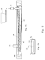
- a suitable system is shown in Figure 2.
- extrusion is carried out in a support mold 6a, 6b by means of a special extrusion head which tapers towards the mouth.
- the special design of the extrusion head enables pressure to be built up, which leads to the favorable discharge conditions of a preform with simultaneous additional compression. Immediately after discharge, the support mold is compressed again, which improves the shape accuracy and enables the surface finish.
- the pasty fiber composite material is conveyed into the extrusion head 13 via a pressure hose 5.
- the flow path of the fiber composite material becomes when entering the extrusion head 13 with a deflection of about 90 ° usually broken. This eliminates the influence on the flow behavior by the delivery hose 5 in the head 13.
- the material is compressed in the extrusion head 13, which tapers towards the mouth, and is given the preform, which is similar to the final shape of the component, by the corresponding design of the head at the mouth. Due to the compression in the extrusion head 13 and the narrowing shape of the head extension above and to the side at the mouth of the extrusion head 13, a largely laminar flow is achieved at the mouth.
- the fiber composite material is discharged and pressed into the support mold 6a, 6b by the narrowing shape of the head extension.
- the special design of the mouth in particular also its weak inclination with respect to the bottom of the support mold 6a, 6b, allows the air to escape and thus prevents it from being trapped.
- a small vibrator 15 on the drag mold 14 supports the entire discharge process and, in conjunction with other processes, brings about a high surface quality of the component.
- FIG. 1 A method using two extruders (duplex extrusion) is shown in FIG.
- two pumps 12 pasty fiber composite materials are each conveyed via a pressure hose 5 into the extrusion head 13a or into the extrusion head 13b.
- the delivery rate can be set separately for each pump 12, which influences the delivery rate and delivery pressure.
- the flow path of the materials is severely broken upon entry into the extrusion heads 13a, 13b with a deflection of preferably approximately 90 °.
- the material is compressed in both extrusion heads and is given the appropriate preforms by the appropriate design of the heads at the mouth, which together are similar to the final shape of the component.
- the compression stage is designed differently depending on the component, so that laminar flow conditions of the same speed arise at the mouth even with uneven profile cross sections.
- the fiber composite material of the first extrusion head 13a is discharged and pressed into the support mold 6a, 6b by the narrowing shape of the head extension.
- the special design of the mouth in particular the head extension at the top and the inclination of the extrusion heads 13a, 13b relative to the bottom of the support mold, allow the air to escape and thus prevent it from being trapped.
- a reinforcement guide 8a can be provided, through which a continuous, oriented reinforcement material can be fed from an unwinding device via a tensioning device (not shown).
- the reinforcement material is guided over the reinforcement guide 8a to the clamping device for the reinforcement 7 and is slightly tensioned.
- the reinforcement material is fed in under constant light tension, for example unwound from spools.
- the guide between the mouths of the two extrusion heads 13a, 13b positions the reinforcement on the first extrusion layer with millimeter precision.
- the fiber composite material of the extrusion head 13b is discharged.
- the elongated upper part of the head 13b presses the second extrusion layer against the first and embeds the additional reinforcement, fabric, cord, spun threads, yarn, rovings, wire, etc. in between.
- endlessly longitudinal and / or transverse reinforced components can be manufactured with good homogeneity.
- fabric and cord allow any choice of reinforcement orientation and thus the determination of the properties depending on the component.
- the method can also be carried out with more than two extrusion heads, whereby an endless, oriented reinforcement does not necessarily have to be provided for each layer. it can also be used for the production of composite materials with or without oriented reinforcement, especially for those with at least one layer of a pasty, fibrous, cementitious building material.
- composite cross-sections from different construction or Materials are manufactured. For example, a core layer with a lower bulk density can be introduced between two cementitious layers.
- the special extrusion process of the present invention in particular the duplex extrusion, is characterized by the following special features:
- the extrusion takes place in a support mold 6a, 6b, whereby precise dimensions of the contour and a smooth, non-porous surface in the region of the support mold are achieved.
- the deformation and compression in the extrusion heads result in a compact structure and ensure good shape even with relatively dry material.
- the surface in particular also becomes denser.
- the duplex resp. Multiplex extrusion enables the reinforcement to be precisely positioned by guide 8a at the mouth between the at least two extrusion heads 13a, 13b.
- the reinforcement level is freely selectable and can therefore be precisely matched to the component and its stress.
- the drag mold 14 causes slow pressure reduction in the molded component. With slight vibration at the same time, a pore-free surface of the component on the mold side and a dimensionally stable contour on the rear of the component are achieved.
- extrusion systems according to the invention have few wearing parts and only require relatively simple extrusion tools. Therefore, you only need a small amount of maintenance and relatively inexpensive extrusion tools.
- extrusion heads 13a, 13b, etc. are preferably separable from one another, so that the “threading” of the reinforcement for the first time is simplified.
Landscapes
- Engineering & Computer Science (AREA)
- Ceramic Engineering (AREA)
- Manufacturing & Machinery (AREA)
- Chemical & Material Sciences (AREA)
- Mechanical Engineering (AREA)
- Press-Shaping Or Shaping Using Conveyers (AREA)
Applications Claiming Priority (2)
| Application Number | Priority Date | Filing Date | Title |
|---|---|---|---|
| CH3654/93 | 1993-12-08 | ||
| CH365493A CH688033A5 (de) | 1993-12-08 | 1993-12-08 | Verfahren fuer die Herstellung von Bauteilen aus faserverstaerkten mineralisch gebundenen Baustoffen. |
Publications (1)
| Publication Number | Publication Date |
|---|---|
| EP0657258A1 true EP0657258A1 (fr) | 1995-06-14 |
Family
ID=4260663
Family Applications (1)
| Application Number | Title | Priority Date | Filing Date |
|---|---|---|---|
| EP94118641A Withdrawn EP0657258A1 (fr) | 1993-12-08 | 1994-11-26 | Procédé pour la fabrication d'éléments de construction, en particulier à partir de matières minérales renforcées de fibres |
Country Status (2)
| Country | Link |
|---|---|
| EP (1) | EP0657258A1 (fr) |
| CH (1) | CH688033A5 (fr) |
Cited By (2)
| Publication number | Priority date | Publication date | Assignee | Title |
|---|---|---|---|---|
| DE19654564A1 (de) * | 1996-12-27 | 1998-07-02 | Fertig Decken Union Gmbh | Aus Beton im Gießverfahren hergestelltes Bauelement oder Bauteil sowie Verfahren zur Herstellung dieses Bauelementes oder Bauteiles |
| DE10037766A1 (de) * | 2000-08-03 | 2002-02-14 | Hochtief Fertigteilbau Gmbh | Spannbetonhohlplatte und Verfahren zur Herstellung derselben |
Citations (14)
| Publication number | Priority date | Publication date | Assignee | Title |
|---|---|---|---|---|
| GB184555A (en) * | 1921-05-10 | 1922-08-10 | William Sykes | Improvements in or relating to the manufacture of lengthy articles of plastic material, with special reference to reinforced concrete |
| DE1121523B (de) * | 1959-02-25 | 1962-01-04 | Gustav Hoke Dr Ing | Verfahren und Vorrichtung zum Herstellen von Koerpern aus Beton, Faserzement u. dgl. entluefteten Massen |
| FR1293755A (fr) * | 1961-05-26 | 1962-05-18 | Eternit Sa | Procédé et dispositif pour fabriquer, dans un moule, un corps à partir d'un mélange aqueux et fibreux |
| US3146508A (en) * | 1959-11-03 | 1964-09-01 | Henry A Berliner | Apparatus for extruding reinforced members |
| GB1143514A (en) * | 1966-06-02 | 1969-02-26 | Uralita Sa | Moulds for the manufacture of asbestos-cement products |
| GB1277309A (en) * | 1969-09-22 | 1972-06-14 | Oscar Lee Reed | Post forming machine |
| DE2734483A1 (de) * | 1977-07-30 | 1979-02-08 | Norbert Colberg | Bauteil aus zementgebundenem faser- und/oder spanmaterial |
| JPS6186209A (ja) * | 1984-10-03 | 1986-05-01 | 株式会社クボタ | 無機質板材の製造方法 |
| JPH01103943A (ja) * | 1987-10-15 | 1989-04-21 | Kubota Ltd | 無機質製品の押出成形方法 |
| DE3903640A1 (de) * | 1988-02-09 | 1989-08-17 | N Proizv Ob Energostroiprom | Verfahren und anlage zur herstellung von hohlkoerpern aus baustoffgemischen, vorzugsweise betongemischen |
| EP0347092A2 (fr) * | 1988-06-11 | 1989-12-20 | Redland Roof Tiles Limited | Procédé pour la fabrication d'éléments de construction en béton |
| JPH0269368A (ja) * | 1988-09-02 | 1990-03-08 | Kubota Ltd | 無機質製品の押出成形方法 |
| WO1993020990A1 (fr) * | 1992-04-14 | 1993-10-28 | Assadollah Redjvani | Procede de moulage de beton en continu par extrusion |
| DE4218710C1 (de) * | 1992-06-06 | 1993-11-18 | Hochtief Ag Hoch Tiefbauten | Anlage zum Herstellen von Tübbingen für eine Tunnelauskleidung |
-
1993
- 1993-12-08 CH CH365493A patent/CH688033A5/de not_active IP Right Cessation
-
1994
- 1994-11-26 EP EP94118641A patent/EP0657258A1/fr not_active Withdrawn
Patent Citations (14)
| Publication number | Priority date | Publication date | Assignee | Title |
|---|---|---|---|---|
| GB184555A (en) * | 1921-05-10 | 1922-08-10 | William Sykes | Improvements in or relating to the manufacture of lengthy articles of plastic material, with special reference to reinforced concrete |
| DE1121523B (de) * | 1959-02-25 | 1962-01-04 | Gustav Hoke Dr Ing | Verfahren und Vorrichtung zum Herstellen von Koerpern aus Beton, Faserzement u. dgl. entluefteten Massen |
| US3146508A (en) * | 1959-11-03 | 1964-09-01 | Henry A Berliner | Apparatus for extruding reinforced members |
| FR1293755A (fr) * | 1961-05-26 | 1962-05-18 | Eternit Sa | Procédé et dispositif pour fabriquer, dans un moule, un corps à partir d'un mélange aqueux et fibreux |
| GB1143514A (en) * | 1966-06-02 | 1969-02-26 | Uralita Sa | Moulds for the manufacture of asbestos-cement products |
| GB1277309A (en) * | 1969-09-22 | 1972-06-14 | Oscar Lee Reed | Post forming machine |
| DE2734483A1 (de) * | 1977-07-30 | 1979-02-08 | Norbert Colberg | Bauteil aus zementgebundenem faser- und/oder spanmaterial |
| JPS6186209A (ja) * | 1984-10-03 | 1986-05-01 | 株式会社クボタ | 無機質板材の製造方法 |
| JPH01103943A (ja) * | 1987-10-15 | 1989-04-21 | Kubota Ltd | 無機質製品の押出成形方法 |
| DE3903640A1 (de) * | 1988-02-09 | 1989-08-17 | N Proizv Ob Energostroiprom | Verfahren und anlage zur herstellung von hohlkoerpern aus baustoffgemischen, vorzugsweise betongemischen |
| EP0347092A2 (fr) * | 1988-06-11 | 1989-12-20 | Redland Roof Tiles Limited | Procédé pour la fabrication d'éléments de construction en béton |
| JPH0269368A (ja) * | 1988-09-02 | 1990-03-08 | Kubota Ltd | 無機質製品の押出成形方法 |
| WO1993020990A1 (fr) * | 1992-04-14 | 1993-10-28 | Assadollah Redjvani | Procede de moulage de beton en continu par extrusion |
| DE4218710C1 (de) * | 1992-06-06 | 1993-11-18 | Hochtief Ag Hoch Tiefbauten | Anlage zum Herstellen von Tübbingen für eine Tunnelauskleidung |
Non-Patent Citations (3)
| Title |
|---|
| DATABASE WPI Week 8624, Derwent World Patents Index; AN 86-152871 * |
| PATENT ABSTRACTS OF JAPAN vol. 13, no. 326 (C - 620) 24 July 1989 (1989-07-24) * |
| PATENT ABSTRACTS OF JAPAN vol. 14, no. 250 (C - 0723) 29 May 1990 (1990-05-29) * |
Cited By (3)
| Publication number | Priority date | Publication date | Assignee | Title |
|---|---|---|---|---|
| DE19654564A1 (de) * | 1996-12-27 | 1998-07-02 | Fertig Decken Union Gmbh | Aus Beton im Gießverfahren hergestelltes Bauelement oder Bauteil sowie Verfahren zur Herstellung dieses Bauelementes oder Bauteiles |
| DE19654564C2 (de) * | 1996-12-27 | 2000-01-20 | Fertig Decken Union Gmbh | Werk- und baustellengerechtes Gießverfahren zum Herstellen eines durch Fasern verstärkten großformatigen Bauteiles mit einer relativ großen Dicke aus Beton |
| DE10037766A1 (de) * | 2000-08-03 | 2002-02-14 | Hochtief Fertigteilbau Gmbh | Spannbetonhohlplatte und Verfahren zur Herstellung derselben |
Also Published As
| Publication number | Publication date |
|---|---|
| CH688033A5 (de) | 1997-04-30 |
Similar Documents
| Publication | Publication Date | Title |
|---|---|---|
| EP0710313B1 (fr) | Dispositif d'ancrage de cables en materiaux composites a haute performance renforces par des fibres | |
| DE69210543T2 (de) | Herstellungsverfahren zum Formen eines Verbundproduktes | |
| DE69115891T2 (de) | Faserverstärkte verbundwerkstoffe | |
| DE69424444T2 (de) | Hochfeste seele für drahtseile | |
| DE69712420T2 (de) | Extrusion von faserverstärkten Thermoplasten | |
| DE19655331B4 (de) | Vorrichtung zur Herstellung von mit Verstärkungsfasern durchsetzten Kunststoffteilen | |
| EP0149195B1 (fr) | Mousse composite à peau integrée et son procédé de fabrication | |
| DE69514662T2 (de) | Verfahren und vorrichtung zum herstellen von körpern aus teilchenförmigem material und daraus hergestellte produkte | |
| WO1990006218A1 (fr) | Preforme en dechets de matiere synthetique files ou extrudes | |
| DE19930920A1 (de) | Langfaserverstärktes thermoplastisches Material und Verfahren zum Herstellen desselben | |
| DE69429736T2 (de) | Verfahren zum herstellen von langfaserverstärkten harzzusammensetzungen | |
| DE69025225T2 (de) | Faserverstärktes Verbundmaterial aus Polymerharz und Verfahren zu seiner Herstellung | |
| EP0364828B1 (fr) | Installation d'imprégnation par extrusion | |
| EP3705250B1 (fr) | Procédé de fabrication d'un composant en béton et dispositif de fabrication de pièce en béton | |
| DE4302409C2 (de) | Zug- oder Felsanker mit angeformtem Gewinde sowie Verfahren zur Herstellung derselben | |
| DE4416160A1 (de) | Verfahren und Vorrichtung zur kontinuierlichen Herstellung faserverstärkter Formkörper aus hydraulisch abbindbaren Massen | |
| EP3141362B1 (fr) | Procede de fabrication d'une structure en mortier ou en beton et systeme adapte | |
| DE19625426A1 (de) | Verbindungsvorrichtung, Verfahren zur Herstellung derselben, Vorrichtung zur Durchführung des Verfahrens und Verwendung der Verbindungsvorrichtung | |
| EP0151930A2 (fr) | Procédé pour la fabrication d'un élément tubulaire et tuyau composite obtenu par ledit procédé | |
| DE3438448C2 (fr) | ||
| EP0657258A1 (fr) | Procédé pour la fabrication d'éléments de construction, en particulier à partir de matières minérales renforcées de fibres | |
| DE3839835A1 (de) | Lang- und kurzfaserverstaerkte gewindestangen und -bolzen aus thermoplastischen kunststoffen | |
| DE1440200B2 (de) | Verbindungselement fuer haengeisolatoren der kappen- und kloeppelbauart in einer isolatorenkette und verfahren zur herstellung solcher verbindungselemente | |
| EP0185960B1 (fr) | Fabrication de matière plastique renforcée | |
| DE69314905T2 (de) | Verfahren zum Herstellen von rohrförmigen Elementen aus kunstharzgebundenen Fasern, die ineinanderschiebbar sind, um eine Angelrute mit kontrollierter Bewegung zu bilden, und mit diesem Verfahren hergestellte Elemente |
Legal Events
| Date | Code | Title | Description |
|---|---|---|---|
| PUAI | Public reference made under article 153(3) epc to a published international application that has entered the european phase |
Free format text: ORIGINAL CODE: 0009012 |
|
| AK | Designated contracting states |
Kind code of ref document: A1 Designated state(s): AT BE CH DE FR IT LI NL |
|
| 17P | Request for examination filed |
Effective date: 19951201 |
|
| 17Q | First examination report despatched |
Effective date: 19980423 |
|
| STAA | Information on the status of an ep patent application or granted ep patent |
Free format text: STATUS: THE APPLICATION IS DEEMED TO BE WITHDRAWN |
|
| 18D | Application deemed to be withdrawn |
Effective date: 20000418 |