EP0657373A2 - Sauggreifer - Google Patents
Sauggreifer Download PDFInfo
- Publication number
- EP0657373A2 EP0657373A2 EP94119351A EP94119351A EP0657373A2 EP 0657373 A2 EP0657373 A2 EP 0657373A2 EP 94119351 A EP94119351 A EP 94119351A EP 94119351 A EP94119351 A EP 94119351A EP 0657373 A2 EP0657373 A2 EP 0657373A2
- Authority
- EP
- European Patent Office
- Prior art keywords
- suction cups
- article
- size
- operative position
- vacuum chuck
- Prior art date
- Legal status (The legal status is an assumption and is not a legal conclusion. Google has not performed a legal analysis and makes no representation as to the accuracy of the status listed.)
- Granted
Links
Images


Classifications
-
- B—PERFORMING OPERATIONS; TRANSPORTING
- B65—CONVEYING; PACKING; STORING; HANDLING THIN OR FILAMENTARY MATERIAL
- B65G—TRANSPORT OR STORAGE DEVICES, e.g. CONVEYORS FOR LOADING OR TIPPING, SHOP CONVEYOR SYSTEMS OR PNEUMATIC TUBE CONVEYORS
- B65G47/00—Article or material-handling devices associated with conveyors; Methods employing such devices
- B65G47/74—Feeding, transfer, or discharging devices of particular kinds or types
- B65G47/90—Devices for picking-up and depositing articles or materials
- B65G47/91—Devices for picking-up and depositing articles or materials incorporating pneumatic, e.g. suction, grippers
- B65G47/918—Devices for picking-up and depositing articles or materials incorporating pneumatic, e.g. suction, grippers with at least two picking-up heads
-
- Y—GENERAL TAGGING OF NEW TECHNOLOGICAL DEVELOPMENTS; GENERAL TAGGING OF CROSS-SECTIONAL TECHNOLOGIES SPANNING OVER SEVERAL SECTIONS OF THE IPC; TECHNICAL SUBJECTS COVERED BY FORMER USPC CROSS-REFERENCE ART COLLECTIONS [XRACs] AND DIGESTS
- Y10—TECHNICAL SUBJECTS COVERED BY FORMER USPC
- Y10S—TECHNICAL SUBJECTS COVERED BY FORMER USPC CROSS-REFERENCE ART COLLECTIONS [XRACs] AND DIGESTS
- Y10S294/00—Handling: hand and hoist-line implements
- Y10S294/907—Sensor controlled device
Definitions
- This invention relates to a vacuum chuck apparatus for chucking an article like a plate, box or the like, and more particularly to a vacuum chuck apparatus which has a plurality of suction cups and in which the number of the suction cups to be actually operated is changed according the size of the article to be handled.
- the vacuum chuck apparatus for chucking an article like a plate, box or the like such as a glass plate, a corrugated box or the like.
- the vacuum chuck apparatus has a plurality of suction cups fixed to a base member such as a chuck frame.
- the suction cups are pressed against a predetermined surface of the article to be chucked and the air in the suction cups is evacuated to make the pressure in the space surrounded by each suction cup and the predetermined surface of the article, whereby the article is chucked by the vacuum chuck apparatus by suction.
- the vacuum chuck apparatus When such a vacuum chuck apparatus is used for transferring articles, the vacuum chuck apparatus should agree with the size of the article. However when separate vacuum chuck apparatuses are prepared for the articles of different sizes, operating cost rises and a large spaces is required.
- a single vacuum chuck apparatus can be used for chucking articles of different sizes.
- An example of such a "free-size" vacuum chuck apparatus is disclosed in Japanese Utility Model Publication No. 47(1972)-12624.
- a plurality of suction cups are mounted in array on a chuck frame.
- the suction cups positioned in the middle of the array are fixed to the chuck frame and are constantly operated irrespective of the size of the article to be chucked, while the suction cups positioned in end portions of the array are mounted on the chuck frame to be movable between an operative position where they can chuck the article by suction together with the fixed suction cups and a retracted position above the operative position.
- the suction cups in the end portions are manually moved to the retracted position and held there by means of engagement members.
- the suction cups in the retracted position is moved to the operative position by manually disengaging the engagement members.
- the suction cups in the end portions of a suction cup array are mounted on the chuck frame to be movable between the operative position and the retracted position above the operative position and at the same time held by arms to be rotatable in a horizontal plane.
- the movable suction cups are manually swung in the horizontal plane when the size of the article to be chucked changes.
- each suction cup is supported by a shaft and a pinion is formed on an upper part of the shaft.
- the pinion is in mesh with a pair of opposed rack members extending in a horizontal direction.
- the position of the suction cup can be manually changed by pushing up the shaft to disengage the pinion from the rack members, moving the shaft along the rack members and then engaging pinion with the rack members again.
- the suction cups are manually moved when changing the size of the articles to be chucked by the vacuum chuck apparatus, and accordingly, in a line where articles of various sizes are transferred mixed together, the line must be stopped to change the positions of the suction cups every time the size of the article changes, which greatly deteriorates the operating efficiency of the line and makes it impossible to use the vacuum chuck apparatus for an unmanned automated system.
- the primary object of the present invention is to provide a free-size vacuum chuck apparatus in which the number of the suction cups to be actually operated can be automatically changed according to the size of the article to be chucked.
- a plurality of suction cups are arranged in array and are supported to be movable up and down independently from each other between an operative position where each of the suction cups can attract the article by suction and a retracted position above the operative position.
- all the suction cups are first positioned in the operative position and some of the suction cups are automatically moved to the retracted position according to a size signal representing the size of the article to be chucked so that only the suction cups necessary for chucking the article of the size represented by the size signal remain in the operative position.
- all the suction cups are first positioned in the retracted position and some of the suction cups are automatically moved to the operative position according to a size signal representing the size of the article to be chucked so that only the suction cups necessary for chucking the article of the size represented by the size signal are positioned in the operative position.
- the article size designating means may be a means which detects the size of the article and outputs a size signal representing the detected size of the article, or a means which outputs a size signal representing the size of the article which is given by an operator or an external article size detecting means.
- the vacuum chuck apparatus of this embodiment may have one or more fixed suction cups which are constantly held in the operative position.
- Such fixed suction cups are generally disposed in the middle of the array of the suction cups.
- the movable suction cups may be normally held in said operative position and selectively moved to the retracted position according to the size of the article to be chucked, or may be normally held in said retracted position and selectively moved to the operative position according to the size of the article to be chucked.
- the drive means may comprise an air cylinder.
- a single acting retracting air cylinder or a double acting air cylinder may be used.
- the pressure at which the suction cup is pressed against the article can be finely adjusted by controlling the pressure of air to be supplied to the air cylinder, which is particularly advantageous when the article to be chucked is fragile, apt to be scratched or soft.
- the movable suction cups are selectively positioned in the operative position or the retracted position automatically according to the size signal representing the size of the article. Accordingly the vacuum chuck apparatus can be automatically adapted to various sizes, and the time and labor required for adapting the apparatus to the size of the article to be chucked can be greatly reduced, which results in great reduction of cost and great improvement of the operating efficiency.
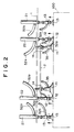
- a vacuum chuck apparatus in accordance with an embodiment of the present invention includes a support structure comprising a chuck frame 1 which is moved up and down by a lift means (not shown) and a sub frame 2 which is fixed to the chuck frame 1 to be opposed to the lower surface of the chuck frame 1 at a predetermined distance therefrom.
- a support structure comprising a chuck frame 1 which is moved up and down by a lift means (not shown) and a sub frame 2 which is fixed to the chuck frame 1 to be opposed to the lower surface of the chuck frame 1 at a predetermined distance therefrom.
- Four suction cups 11 are fixed to the sub frame 2 by way of suction cup holders 14, and four suction cups 12 and four suction cups 13 are mounted on the chuck frame 1 to surround the four suction cups 11.
- the suction cups 12 and 13 mounted on the chuck frame 1 to be movable up and down and the suction cups 12 are positioned nearer to the center of the chuck frame 1 than the suction cups 13.
- the suction cups 12 will be referred to as “the inner movable suction cups 12" and the suction cups 13 will be referred to as “the outer movable suction cups 13" while the suction cups 11 will be referred to as “the fixed suction cups 11", hereinbelow.
- Each of the fixed suction cups 11 is fixed to the sub frame 2 with its attracting surface faced downward and connected to a vacuum pump 40 through vacuum hoses 35 and 36 and an electromagnetic valve 37.
- the vacuum hoses 35 for a pair of fixed suction cups 11 which are diagonally opposed to each other (See Figure 3) are connected to one vacuum hose 36.
- the electromagnetic valve 37 is opened and closed by a predetermined control signal.
- the movable suction cups 12 and 13 are mounted on the chuck frame 1 by way of single acting retracting air cylinders 22 and 21 with their attracting surface faced downward.
- the movable suction cups 12 and 13 are normally held in the operative position shown by the solid line in Figure 2, and are lifted to the retracted position shown by the dotted line when the size of the article 100 to be chucked is small and they need not be operated.
- the air cylinders 22 and 21 lift the movable suction cups 12 and 13 to the retracted position under the pressure of air supplied from an air pump 60.
- the air cylinders 22 for the inner movable suction cups 12 and the air cylinders 21 for the outer movable suction cups 13 are connected to the air pump 60 through separate air lines. That is, each of the air cylinders 22 for the inner movable suction cups 12 is connected to a common air pipe 53a through a discrete air hose 52a, and the common air pipe 53a is connected to the air pump 60 through air hoses 54a and 56a.
- An electromagnetic valve 55a is provided between the air hoses 54a and 56a.
- Each of the air cylinders 21 for the outer movable suction cups 13 is connected to a common air pipe 53b through a discrete air hose 52b, and the common air pipe 53b is connected to the air pump 60 through air hoses 54b and 56b.
- An electromagnetic valve 55b is provided between the air hoses 54b and 56b. The electromagnetic valves 55a and 55b are separately opened and closed by a control signal.
- Each of the inner movable suction cups 12 is connected to the vacuum pump 40 through a discrete vacuum hose 32a, a common air pipe 33a and a vacuum hose 34a and an electromagnetic valve 39a is provided between the vacuum hose 34a and the vacuum pump 40.
- Each of the outer movable suction cups 13 is connected to the vacuum pump 40 through a discrete vacuum hose 32b, a common air pipe 33b and a vacuum hose 34b and an electromagnetic valve 39b is provided between the vacuum hose 34b and the vacuum pump 40.
- the electromagnetic valves 39a and 39b are separately opened and closed by a control signal.
- the vacuum chuck apparatus is further provided with an article size designating means 80 which outputs a size signal S representing the size of the article 100 to be chucked and a controller 70 which outputs the control signals for selectively opening and closing the electromagnetic valves 55a, 55b, 37, 39a and 39b according to the size signal S.
- the article size designating means 80 may be a means which detects the size of the article 100 and outputs a size signal S representing the detected size of the article 100, or a means which outputs a size signal S representing the size of the article 100 which is given by an operator or an external article size detecting means.
- the vacuum chuck apparatus of this embodiment operates in the following manner.
- the chuck frame 1 is moved downward until the suction cups in the operative position (11; 11, 12 and 13; 11 and 12; or 11 and 13) are brought into abutment against the upper surface of the article 100 and then further moved downward by about 10mm (buffer stroke) to press the suction cups against the upper surface of the article 100.
- the electromagnetic valves for supplying suction to the suction cups in the operative position are opened and suction is supplied to the suction cups, whereby the article 100 is attracted by the suction cups by suction.
- the chuck frame 1 is lifted in this state, the article 100 is also lifted.
- the chuck frame 1 When the article 100 is to be put on a place, the chuck frame 1 is moved downward to position the article 100 on the place and the electromagnetic valves for supplying suction to the suction cups in the operative position are closed to stop supply of suction to the suction cups. Thereafter air is introduced into the suction cups through vent holes (not shown) and the article 100 is released from the suction cups.
- the fixed suction cups 11 are constantly held in the operative position, they are normally operated irrespective of the size of the article 100.
- the vacuum chuck apparatus of this embodiment is controlled in the following manner.
- the article size designating means 80 When the size of the article 100 is as indicated at d in Figure 3, the article size designating means 80 outputs a size signal S d representing the size d and the size signal S d is input into the controller 70.
- the controller 70 causes all the suction cups 11, 12 and 13 to operate. That is, the controller 70 outputs the control signals to close the electromagnetic valves 55a and 55b so that the air cylinders 22 and 21 for the inner movable suction cups 12 and the outer movable suction cups 13 are not supplied with air from the air pump 60, whereby the air cylinders 22 and 21 are all kept stretched and the suction cups 12 and 13 are all held in the operative position. In the operative position, all the suction cups 11 to 13 are positioned in a horizontal plane.
- the controller 70 outputs the control signals to open the electromagnetic valves 37, 39a and 39b so that all the suction cups 11 to 13 are supplied with suction from the vacuum pump 40, whereby the article 100 is attracted by the suction cups 11 to 13 by suction.
- the controller 70 causes the electromagnetic valves 37, 39a and 39b to close so that supply of suction to the suction cups 11 to 13 is cut.
- the article size designating means 80 When the size of the article 100 is as indicated at c in Figure 3, the article size designating means 80 outputs a size signal S c representing the size c and the size signal S c is input into the controller 70.
- the controller 70 causes the inner movable suction cups 12 which are not necessary for chucking the article 100 of the size c to move to the retracted position.
- the controller 70 outputs the control signal to open the electromagnetic valve 55a so that the air cylinders 22 for the inner movable suction cups 12 are supplied with air from the air pump 60 with the electromagnetic valve 55b kept closed, whereby the air cylinders 22 for the inner movable suction cups 12 are caused to contract and the inner movable suction cups 12 are lifted to the retracted position while the air cylinders 21 for the outer movable suction cups 13 are kept stretched and the outer movable suction cups 13 are kept in the operative position.
- the controller 70 outputs the control signals to open the electromagnetic valves 37 and 39b and to keep the electromagnetic valve 39a closed so that the suction cups 11 and 13 are supplied with suction from the vacuum pump 40, whereby the article 100 is attracted by the suction cups 11 and 13 by suction.
- the controller 70 causes the electromagnetic valves 37 and 39b to close so that supply of suction to the suction cups 11 and 13 is cut.
- the article size designating means 80 When the size of the article 100 is as indicated at b in Figure 3, the article size designating means 80 outputs a size signal S b representing the size b and the size signal S b is input into the controller 70.
- the controller 70 causes the outer movable suction cups 13 which are not necessary for chucking the article 100 of the size b to move to the retracted position.
- the controller 70 outputs the control signal to open the electromagnetic valve 55b so that the air cylinders 21 for the outer movable suction cups 13 are supplied with air from the air pump 60 with the electromagnetic valve 55a kept closed, whereby the air cylinders 21 for the outer movable suction cups 13 are caused to contract and the outer movable suction cups 13 are lifted to the retracted position while the air cylinders 22 for the inner movable suction cups 12 are kept stretched and the inner movable suction cups 12 are kept in the operative position.
- the controller 70 outputs the control signals to open the electromagnetic valves 37 and 39a and to keep the electromagnetic valve 39b closed so that the suction cups 11 and 12 are supplied with suction from the vacuum pump 40, whereby the article 100 is attracted by the suction cups 11 and 12 by suction.
- the controller 70 causes the electromagnetic valves 37 and 39a to close so that supply of suction to the suction cups 11 and 12 is cut.
- the article size designating means 80 When the size of the article 100 is as indicated at a in Figure 3, the article size designating means 80 outputs a size signal S a representing the size a and the size signal S a is input into the controller 70.
- the controller 70 causes the inner and outer movable suction cups 12 and 13 which are not necessary for chucking the article 100 of the size b to move to the retracted position.
- the controller 70 outputs the control signals to open the electromagnetic valve 55a and 55b so that the air cylinders 22 and 21 for the inner and outer movable suction cups 12 and 13 are supplied with air from the air pump 60, whereby the air cylinders 22 and 21 for the inner and outer movable suction cups 12 and 13 are caused to contract and the inner and outer movable suction cups 13 are lifted to the retracted position.
- the controller 70 outputs the control signals to open the electromagnetic valves 37 and to keep the electromagnetic valves 39a and 39b closed so that the fixed suction cups 11 are supplied with suction from the vacuum pump 40, whereby the article 100 is attracted by the fixed suction cups 11 by suction.
- the controller 70 causes the electromagnetic valves 37 to close so that supply of suction to the fixed suction cups 11 is cut.
- a vacuum chuck apparatus shown in Figure 1 was made in the following specifications. That is, the fixed suction cups 11 were of urethane rubber and 80mm in diameter. The inner and outer suction cups 12 and 13 were of urethane rubber and 50mm in diameter. The air cylinders 21 and 22 were 20mm in diameter and 25mm in stroke.
- the vacuum chuck apparatus was housed in a casing of 500mm x 450mm x 150mm made by welding thin iron plates and was about 35kg in weight.
- corrugated boxes containing therein photosensitive materials were handled.
- the sizes and the weights of the corrugated boxes were as follows.
- the maximum load of the vacuum chuck apparatus was 60kg, the maximum lifting speed was 1000mm/sec, and the maximum rotational speed about the vertical axis and the horizontal axis was 2.44 rad/sec (140°C/sec).
- the article positioning accuracy of the apparatus was within plus or minus 1mm.
- the movable suction cups 12 and 13 are selectively positioned in the operative position or the retracted position automatically according to the size signal representing the size of the article. Accordingly the vacuum chuck apparatus can be automatically adapted to various sizes, and the time and labor required for adapting the apparatus to the size of the article to be chucked can be greatly reduced, which results in great reduction of cost and great improvement of the operating efficiency.
- a single acting retracting air cylinder is used as the drive means for moving the movable suction cup between the operative position and the retracted position
- other various drive means may be used.
- a double acting air cylinder may be used and hydraulic or mechanical drive means may be used.
- the pressure at which the suction cup is pressed against the article can be finely adjusted by controlling the pressure of air to be supplied to the air cylinder, which is particularly advantageous when the article to be chucked is fragile, apt to be scratched or soft.
Landscapes
- Engineering & Computer Science (AREA)
- Mechanical Engineering (AREA)
- Sheets, Magazines, And Separation Thereof (AREA)
- Manipulator (AREA)
Applications Claiming Priority (3)
| Application Number | Priority Date | Filing Date | Title |
|---|---|---|---|
| JP30789493 | 1993-12-08 | ||
| JP5307894A JPH07157117A (ja) | 1993-12-08 | 1993-12-08 | 板状体または箱体の真空チャック装置 |
| JP307894/93 | 1993-12-08 |
Publications (3)
| Publication Number | Publication Date |
|---|---|
| EP0657373A2 true EP0657373A2 (de) | 1995-06-14 |
| EP0657373A3 EP0657373A3 (de) | 1996-03-13 |
| EP0657373B1 EP0657373B1 (de) | 2000-03-29 |
Family
ID=17974451
Family Applications (1)
| Application Number | Title | Priority Date | Filing Date |
|---|---|---|---|
| EP94119351A Expired - Lifetime EP0657373B1 (de) | 1993-12-08 | 1994-12-07 | Sauggreifer |
Country Status (4)
| Country | Link |
|---|---|
| US (1) | US5609377A (de) |
| EP (1) | EP0657373B1 (de) |
| JP (1) | JPH07157117A (de) |
| DE (1) | DE69423704T2 (de) |
Cited By (16)
| Publication number | Priority date | Publication date | Assignee | Title |
|---|---|---|---|---|
| EP0989080A1 (de) * | 1998-09-23 | 2000-03-29 | Soremartec S.A. | Greifvorrichtung zum automatischen Verpacken von Gegenständen |
| EP1232990A3 (de) * | 2001-02-15 | 2005-10-26 | Trumpf Sachsen GmbH | Einzelsteuerung für Sauggreifer in einem eine Vielzahl von Sauggreifern enthaltenden Ladegerät |
| DE10102106B4 (de) * | 2001-01-18 | 2008-05-29 | Trumpf Sachsen Gmbh | Verfahren und Vorrichtung zum Vereinzeln von dünnen flächigen Werkstücken mittels Saugern |
| CN104039209A (zh) * | 2011-11-18 | 2014-09-10 | 耐克国际有限公司 | 可变换板制造真空工具 |
| CN106914914A (zh) * | 2017-03-14 | 2017-07-04 | 黄河科技学院 | 一种用于机械制造的机械夹爪 |
| CN107572248A (zh) * | 2017-08-28 | 2018-01-12 | 昆山拓誉自动化科技有限公司 | 一种基于真空吸盘的输送装置 |
| US9937585B2 (en) | 2011-11-18 | 2018-04-10 | Nike, Inc. | Multi-functional manufacturing tool |
| CN109482485A (zh) * | 2018-12-28 | 2019-03-19 | 天津开发区天水华源机电设备技术有限公司 | 一种用于孔板填充的筛板装填机 |
| WO2019147697A1 (en) * | 2018-01-24 | 2019-08-01 | Amazon Technologies, Inc. | Robotic item handling using a variable area manipulator |
| CN110116922A (zh) * | 2019-05-28 | 2019-08-13 | 浙江工业大学 | 一种采用梯度吸附方式的无纺布自动分层装置及其方法 |
| CN111846941A (zh) * | 2019-04-26 | 2020-10-30 | J.施迈茨有限公司 | 真空抓持器 |
| WO2021045944A1 (en) * | 2019-09-04 | 2021-03-11 | The Steelastic Company, Llc | Transfer tooling for varying tire belt sizes |
| CN113371584A (zh) * | 2021-04-15 | 2021-09-10 | 芜湖市容川机电科技股份有限公司 | 一种齿轮箱体吊装装置 |
| CN113579810A (zh) * | 2021-08-03 | 2021-11-02 | 湖北中天瑞能科技发展有限公司 | 一种用于机床加工的高精度液压夹具 |
| CN117697669A (zh) * | 2024-01-24 | 2024-03-15 | 中冶东方工程技术有限公司 | 一种多规格异形零件磁吸喷码阵列式夹具及工作方法 |
| US12313395B2 (en) | 2011-11-18 | 2025-05-27 | Nike, Inc. | Automated 3-D modeling of shoe parts |
Families Citing this family (97)
| Publication number | Priority date | Publication date | Assignee | Title |
|---|---|---|---|---|
| JP3225336B2 (ja) * | 1995-07-13 | 2001-11-05 | 株式会社新川 | リードフレームの吸着保持装置 |
| GB9623306D0 (en) * | 1996-11-08 | 1997-01-08 | Palamatic Handling Syst | Baggage handling device |
| US6202999B1 (en) | 1997-02-14 | 2001-03-20 | Dek Printing Machines Ltd. | Workpiece support device |
| GB9703082D0 (en) * | 1997-02-14 | 1997-04-02 | Dek Printing Machines Ltd | Workpiece support device |
| US6394519B1 (en) * | 1998-03-27 | 2002-05-28 | R&D Engineering & Macining, Inc. | Adjustable pick-and-place tool for an automated robotic device or the like |
| DE19817426B4 (de) * | 1998-04-18 | 2004-06-09 | J. Schmalz Gmbh | Greifersystem, insbesondere Vakuumgreifersystem |
| JP2000006075A (ja) * | 1998-06-17 | 2000-01-11 | Sanken Electric Co Ltd | 電子素子支持板又は電子部品の集合体の搬送装置 |
| US6131973A (en) * | 1998-10-01 | 2000-10-17 | Sikorsky Aircraft Corporation | Vacuum transfer device |
| JP4035901B2 (ja) * | 1998-10-09 | 2008-01-23 | 村田機械株式会社 | 板材搬送装置 |
| US6345818B1 (en) | 1998-10-26 | 2002-02-12 | Fanuc Robotics North America Inc. | Robotic manipulator having a gripping tool assembly |
| DE29907404U1 (de) | 1999-04-28 | 1999-09-23 | Weinmann, Peter, 91217 Hersbruck | Vorrichtung zum Auflegen von Gegenständen |
| US6196532B1 (en) | 1999-08-27 | 2001-03-06 | Applied Materials, Inc. | 3 point vacuum chuck with non-resilient support members |
| US7367601B2 (en) * | 2000-06-29 | 2008-05-06 | Shibaura Mechatronics Corporation | Substrate transfer apparatus and substrate transfer method |
| AUPR315301A0 (en) * | 2001-02-19 | 2001-03-15 | Silverbrook Research Pty. Ltd. | An Apparatus (ART102) |
| JP2002263981A (ja) * | 2001-03-14 | 2002-09-17 | Murata Mach Ltd | 板材吸着持ち上げ装置の吸着制御装置 |
| DE10153784B4 (de) * | 2001-04-12 | 2005-02-03 | Trumpf Sachsen Gmbh | Modulares Steuersystem für eine Ladevorrichtung mit gezielter Sauggreifersteuerung |
| DE10140248B4 (de) * | 2001-08-09 | 2006-09-28 | J. Schmalz Gmbh | Unterdruckhandhabungseinrichtung |
| US6796106B1 (en) | 2001-08-24 | 2004-09-28 | Drago Bulich | Rotating vacuum assisted carousel for packaging cable |
| ITMI20020267A1 (it) * | 2002-02-12 | 2003-08-12 | Bavelloni Z Spa | Macchina automatica per la lavorazione di materiali in lastra in particolare lastre di vetro |
| US6979032B2 (en) * | 2002-11-15 | 2005-12-27 | Fmc Technologies, Inc. | Vacuum pick-up head with vacuum supply valve |
| US20040240981A1 (en) * | 2003-05-29 | 2004-12-02 | I-Scan Robotics | Robot stacking system for flat glass |
| US7641438B2 (en) * | 2003-08-14 | 2010-01-05 | Keyes Fibre Corporation | Variable-sized molded product tray denesting apparatus |
| US7309089B2 (en) * | 2004-02-04 | 2007-12-18 | Delaware Capital Formation, Inc. | Vacuum cup |
| US7766596B2 (en) * | 2004-03-30 | 2010-08-03 | Jlg Industries, Inc. | Attachment for a telescopic material handler for manipulating a load with five degrees of freedom |
| DE102004017898B4 (de) * | 2004-04-13 | 2008-07-10 | Festo Ag & Co | Saugvorrichtung und damit ausgestattete Handhabungsvorrichtung |
| DE102004042825B3 (de) * | 2004-08-28 | 2006-01-05 | J. Schmalz Gmbh | Verfahren zum Betreiben einer Unterdruckhandhabungseinrichtung |
| US7281739B2 (en) * | 2004-09-01 | 2007-10-16 | Delaware Capital Formation, Inc. | Adjustable mount for vacuum cup with offset mounting post and swivel |
| US7292427B1 (en) * | 2004-10-12 | 2007-11-06 | Kla-Tencor Technologies Corporation | Pin lift chuck assembly for warped substrates |
| US7296834B2 (en) * | 2004-10-14 | 2007-11-20 | Aidco International, Inc. | Air-powered vacuum tool for handling multiple workpieces |
| US7540309B2 (en) | 2005-07-11 | 2009-06-02 | Delaware Capital Formation, Inc. | Auto-release vacuum device |
| JP4580327B2 (ja) * | 2005-11-21 | 2010-11-10 | 東京エレクトロン株式会社 | 被処理体の取り出し方法及びプログラム記憶媒体並びに載置機構 |
| US7628434B2 (en) * | 2006-07-12 | 2009-12-08 | Honda Motor Co., Ltd. | Vacuum-operated vehicle glass handling system |
| DE102006046624A1 (de) * | 2006-09-29 | 2008-04-03 | Brötje-Automation GmbH | Verfahren und Transportvorrichtung zum Transportieren von Gegenständen |
| FR2907100B1 (fr) * | 2006-10-11 | 2010-10-01 | Sidel Participations | Installation d'emballage et de conditionnement. |
| US7798546B2 (en) * | 2006-11-09 | 2010-09-21 | Delaware Capital Formation, Inc. | Material handling device with level indicator |
| KR100817254B1 (ko) | 2007-03-27 | 2008-03-27 | 한국뉴매틱(주) | 내장 진공펌프를 갖는 레벨 보정기 |
| JP4655074B2 (ja) * | 2007-07-27 | 2011-03-23 | トヨタ自動車株式会社 | ワーク搬送装置およびワーク設置方法 |
| US20090142169A1 (en) * | 2007-11-30 | 2009-06-04 | Teradyne, Inc. | Vacuum Assisted Manipulation of Objects |
| ES2351466B1 (es) * | 2008-05-20 | 2011-11-29 | Europea De Soluciones Alimentarias, S.L. | Pinza para cuerpos esféricos o similares. |
| US7950708B2 (en) * | 2008-08-15 | 2011-05-31 | Amf Automation Technologies, Inc. | Programmable zoned end effector |
| US8251415B2 (en) | 2010-04-20 | 2012-08-28 | AMF automation Technologies, LLC | End effector with suction cups having internal valves |
| US8864200B2 (en) | 2010-04-20 | 2014-10-21 | AMF automation Technologies, LLC | End effector with internal valve |
| US8684434B2 (en) | 2011-11-02 | 2014-04-01 | AMF automation Technologies, LLC | End effector with internal valve |
| US8944481B2 (en) * | 2010-12-31 | 2015-02-03 | Fundacion Tecnalia Research & Innovation | Gripping device for manipulating flexible elements |
| US8528955B2 (en) | 2011-01-24 | 2013-09-10 | AMF automation Technologies, LLC | Robot end effector with cable management |
| US10552551B2 (en) | 2011-11-18 | 2020-02-04 | Nike, Inc. | Generation of tool paths for shore assembly |
| US8958901B2 (en) | 2011-11-18 | 2015-02-17 | Nike, Inc. | Automated manufacturing of shoe parts |
| US8960745B2 (en) * | 2011-11-18 | 2015-02-24 | Nike, Inc | Zoned activation manufacturing vacuum tool |
| US8755925B2 (en) | 2011-11-18 | 2014-06-17 | Nike, Inc. | Automated identification and assembly of shoe parts |
| US8696043B2 (en) * | 2011-11-18 | 2014-04-15 | Nike, Inc. | Hybrid pickup tool |
| US9451810B2 (en) | 2011-11-18 | 2016-09-27 | Nike, Inc. | Automated identification of shoe parts |
| JP5932365B2 (ja) * | 2012-01-26 | 2016-06-08 | 平田機工株式会社 | 保持装置及び保持方法 |
| CN102554543A (zh) * | 2012-02-24 | 2012-07-11 | 沪东中华造船(集团)有限公司 | 一种大规格铝合金带筋板真空吸盘式吊运装置 |
| CN102830524A (zh) * | 2012-09-04 | 2012-12-19 | 京东方科技集团股份有限公司 | 一种模组组装设备 |
| EP2814767B1 (de) * | 2013-01-30 | 2016-08-24 | LISEC Austria GmbH | Vorrichtung zum stapeln und entstapeln von plattenförmigen gegenständen |
| AT13964U1 (de) * | 2013-01-30 | 2015-01-15 | Inova Lisec Technologiezentrum | Verfahren und Vorrichtung zum Stapeln und Entstapeln von plattenförmigen Gegenständen |
| DE102014206308B4 (de) * | 2014-04-02 | 2021-07-22 | J. Schmalz Gmbh | Handhabungsanlage und Verfahren zum Betreiben einer Handhabungsanlage |
| US9205558B1 (en) * | 2014-07-16 | 2015-12-08 | Google Inc. | Multiple suction cup control |
| CN106794967B (zh) * | 2014-10-13 | 2019-05-28 | J.施迈茨有限公司 | 电池夹具 |
| US20160214812A1 (en) * | 2015-01-23 | 2016-07-28 | R.A. Pearson Company | End of Arm Tool for Grasping |
| KR102322479B1 (ko) | 2015-02-25 | 2021-11-05 | 삼성디스플레이 주식회사 | 기판 분리장치 |
| US9823160B2 (en) * | 2015-04-02 | 2017-11-21 | The Boeing Company | Apparatus and methods for testing suction cups mounted to a track |
| NL2014635B1 (en) * | 2015-04-14 | 2017-01-20 | Vmi Holland Bv | Gripper, gripper assembly and method for gripping a tire component. |
| WO2016194564A1 (ja) * | 2015-05-29 | 2016-12-08 | 株式会社村田製作所 | 吸引装置 |
| CN106312874B (zh) * | 2015-06-25 | 2018-05-22 | 江苏银环新能源科技有限公司 | 双玻无边框组件用挂钩自动装配装置 |
| CN105328706B (zh) * | 2015-11-16 | 2017-07-28 | 深圳博美德机器人股份有限公司 | 吸取装置和机器人 |
| KR101659517B1 (ko) | 2016-03-15 | 2016-09-23 | (주)브이텍 | 진공 펌프를 포함하는 진공 그리퍼 유닛 |
| CN105960106A (zh) * | 2016-04-21 | 2016-09-21 | 京东方科技集团股份有限公司 | 假压头及其工作方法 |
| EP3263292B1 (de) * | 2016-06-28 | 2025-07-16 | Tata Consultancy Services Limited | Adaptive greifervorrichtung |
| US10300611B2 (en) * | 2016-08-05 | 2019-05-28 | Mgs Machine Corporation | End effector assembly and method of operation to grasp non-planar articles |
| US9782901B1 (en) * | 2017-01-24 | 2017-10-10 | Bingotimes Digital Technology Co., Ltd. | Robotic arm suction cup capable of eliminating negative pressure |
| EP3369525A1 (de) * | 2017-03-01 | 2018-09-05 | Airbus SAS | Vorrichtung zum spannen eines roboterwerkzeugs auf einem werkstück |
| JP7013036B2 (ja) * | 2017-04-25 | 2022-01-31 | 株式会社Tism | 穿孔装置 |
| US11235939B2 (en) * | 2017-08-10 | 2022-02-01 | Kongsberg Precision Cutting Systems Belgium Bv | Vacuum lifter |
| US10889006B2 (en) * | 2017-10-24 | 2021-01-12 | HKC Corporation Limited | Suction device, suction system and handling equipment |
| CN108423427B (zh) * | 2018-03-05 | 2024-10-25 | 菲尼克斯(南京)智能制造技术工程有限公司 | 真空吸取装置和方法 |
| JP7117126B2 (ja) * | 2018-04-02 | 2022-08-12 | Kyoto Robotics株式会社 | ピッキング装置及びその方法 |
| US10611037B1 (en) * | 2018-06-15 | 2020-04-07 | Amazon Technologies, Inc. | Concentric suction cup array for end-of-arm tool |
| US10926403B1 (en) * | 2018-10-24 | 2021-02-23 | Amazon Technologies, Inc. | Gripping tool having adjustable gripping area, and related methods |
| CN109773821A (zh) * | 2019-01-09 | 2019-05-21 | 清华大学 | 一种吸盘手装置、机械臂设备及检测抓取状态方法 |
| US12202127B2 (en) * | 2019-03-31 | 2025-01-21 | Robotiq Inc. | Adjustable suction gripper |
| CN109975212B (zh) * | 2019-05-05 | 2024-08-06 | 南京光声超构材料研究院有限公司 | 移动装置及表面检测装置 |
| US11911894B2 (en) * | 2019-05-09 | 2024-02-27 | Intelligrated Headquarters, Llc | Method and system for manipulating articles |
| US10913165B1 (en) | 2019-05-31 | 2021-02-09 | Amazon Technologies, Inc. | Rotating end of arm tool including asymmetrical independently controllable suction zones |
| US11325266B1 (en) * | 2019-06-21 | 2022-05-10 | Amazon Technologies, Inc. | Bellows valve for vacuum systems |
| US11007654B2 (en) * | 2019-06-21 | 2021-05-18 | Intelligrated Headquarters, Llc | End manipulator for package picking and placing |
| CN211569380U (zh) * | 2019-11-15 | 2020-09-25 | 泰科电子(上海)有限公司 | 真空吸附模块 |
| TWI702179B (zh) * | 2019-12-05 | 2020-08-21 | 所羅門股份有限公司 | 取物系統及方法 |
| CN111098328A (zh) * | 2019-12-31 | 2020-05-05 | 昆山精讯电子技术有限公司 | 液晶面板抓取机械手 |
| JP6832599B1 (ja) * | 2020-02-20 | 2021-02-24 | 株式会社Mujin | グリッピング機構を有するロボットシステム |
| WO2022034709A1 (ja) * | 2020-08-11 | 2022-02-17 | 日東電工株式会社 | 枚葉光学フィルムの持ち上げ方法、及びその装置 |
| KR102897586B1 (ko) * | 2020-11-30 | 2025-12-10 | 삼성전자주식회사 | 기판 이송 장치 |
| US11840410B2 (en) * | 2020-12-08 | 2023-12-12 | Idaho Forest Group, LLC | Robotic system and method of stacking and unstacking wood boards and related materials and of stacking wood spacers and related materials |
| US11833669B2 (en) * | 2021-03-31 | 2023-12-05 | Dexterity, Inc. | Suction-based end effector with mixed cup sizes |
| CN115009629A (zh) * | 2022-03-02 | 2022-09-06 | 合肥龙旗智能科技有限公司 | 产品附件信息化管理方法、系统及附件装载装置及设备 |
| CN118323872A (zh) * | 2024-06-03 | 2024-07-12 | 意锐科(宁波)智能科技有限公司 | 一种便于转运的码垛机构 |
| CN119142976A (zh) * | 2024-11-15 | 2024-12-17 | 中集安瑞环科技股份有限公司 | 一种真空吸盘吊具 |
Family Cites Families (12)
| Publication number | Priority date | Publication date | Assignee | Title |
|---|---|---|---|---|
| DE297381C (de) * | ||||
| US4648588A (en) * | 1985-06-12 | 1987-03-10 | Rca Corporation | Articulated manipulation device |
| GB8602105D0 (en) * | 1986-01-29 | 1986-03-05 | Precision Eng Products Suffolk | Automatic article handling methods |
| DE3629968A1 (de) * | 1986-09-03 | 1988-03-10 | Messerschmitt Boelkow Blohm | Vorrichtung zum aufnehmen und ablegen von zuschnitten |
| FR2604984B1 (fr) * | 1986-10-08 | 1991-07-12 | Cazas Sarl Ets | Dispositif de securite pour appareil a depression |
| FR2628725B1 (fr) * | 1988-03-18 | 1990-08-10 | Applic Procedes Electro Mec | Dispositif de levage a ventouses |
| FR2633265B1 (fr) * | 1988-06-24 | 1991-06-07 | Centre Tech Cuir Chaussure | Dispositif pour la prehension de pieces souples isolees ou adjacentes, leur manipulation et leur depose, notamment de pieces en cuir et similaires |
| FR2639335A1 (fr) * | 1988-11-24 | 1990-05-25 | Centre Tech Cuir Chaussure | Dispositif a elements de prehension multiples, pour la saisie d'objets isoles |
| JP2699494B2 (ja) * | 1988-12-06 | 1998-01-19 | 松下電器産業株式会社 | 製品保持装置 |
| FR2642055A1 (de) * | 1989-01-20 | 1990-07-27 | Radiotechnique Compelec | |
| US5048811A (en) * | 1989-07-31 | 1991-09-17 | Aluminum Company Of America | Single head device for removing alternate articles from a stack of the articles |
| JPH0764450B2 (ja) * | 1990-06-08 | 1995-07-12 | アイダエンジニアリング株式会社 | 板材ピックアップ装置 |
-
1993
- 1993-12-08 JP JP5307894A patent/JPH07157117A/ja active Pending
-
1994
- 1994-12-07 DE DE69423704T patent/DE69423704T2/de not_active Expired - Lifetime
- 1994-12-07 EP EP94119351A patent/EP0657373B1/de not_active Expired - Lifetime
- 1994-12-08 US US08/351,698 patent/US5609377A/en not_active Expired - Lifetime
Cited By (27)
| Publication number | Priority date | Publication date | Assignee | Title |
|---|---|---|---|---|
| EP0989080A1 (de) * | 1998-09-23 | 2000-03-29 | Soremartec S.A. | Greifvorrichtung zum automatischen Verpacken von Gegenständen |
| DE10102106B4 (de) * | 2001-01-18 | 2008-05-29 | Trumpf Sachsen Gmbh | Verfahren und Vorrichtung zum Vereinzeln von dünnen flächigen Werkstücken mittels Saugern |
| EP1232990A3 (de) * | 2001-02-15 | 2005-10-26 | Trumpf Sachsen GmbH | Einzelsteuerung für Sauggreifer in einem eine Vielzahl von Sauggreifern enthaltenden Ladegerät |
| CN106743602A (zh) * | 2011-11-18 | 2017-05-31 | 耐克创新有限合伙公司 | 可变换板制造真空工具 |
| US11273514B2 (en) | 2011-11-18 | 2022-03-15 | Nike, Inc. | Multi-functional manufacturing tool |
| US9937627B2 (en) | 2011-11-18 | 2018-04-10 | Nike, Inc. | Manufacturing vacuum tool with selective activation of pickup zones |
| US9937585B2 (en) | 2011-11-18 | 2018-04-10 | Nike, Inc. | Multi-functional manufacturing tool |
| US12313395B2 (en) | 2011-11-18 | 2025-05-27 | Nike, Inc. | Automated 3-D modeling of shoe parts |
| CN104039209A (zh) * | 2011-11-18 | 2014-09-10 | 耐克国际有限公司 | 可变换板制造真空工具 |
| US11911893B2 (en) | 2011-11-18 | 2024-02-27 | Nike, Inc. | Manufacturing tool |
| US11389972B2 (en) | 2011-11-18 | 2022-07-19 | Nike, Inc. | Manufacturing tool with selective activation of pickup zones |
| CN106914914A (zh) * | 2017-03-14 | 2017-07-04 | 黄河科技学院 | 一种用于机械制造的机械夹爪 |
| CN107572248A (zh) * | 2017-08-28 | 2018-01-12 | 昆山拓誉自动化科技有限公司 | 一种基于真空吸盘的输送装置 |
| WO2019147697A1 (en) * | 2018-01-24 | 2019-08-01 | Amazon Technologies, Inc. | Robotic item handling using a variable area manipulator |
| US10902377B2 (en) | 2018-01-24 | 2021-01-26 | Amazon Technologies, Inc. | Robotic item handling using a variable area manipulator |
| CN109482485A (zh) * | 2018-12-28 | 2019-03-19 | 天津开发区天水华源机电设备技术有限公司 | 一种用于孔板填充的筛板装填机 |
| CN111846941A (zh) * | 2019-04-26 | 2020-10-30 | J.施迈茨有限公司 | 真空抓持器 |
| US11059186B2 (en) | 2019-04-26 | 2021-07-13 | J.Schmalz Gmbh | Vaccum gripper |
| EP3733572A1 (de) * | 2019-04-26 | 2020-11-04 | J. Schmalz GmbH | Flächensauggreifer |
| CN110116922B (zh) * | 2019-05-28 | 2023-06-06 | 浙江工业大学 | 一种采用梯度吸附方式的无纺布自动分层装置及其方法 |
| CN110116922A (zh) * | 2019-05-28 | 2019-08-13 | 浙江工业大学 | 一种采用梯度吸附方式的无纺布自动分层装置及其方法 |
| CN114364522A (zh) * | 2019-09-04 | 2022-04-15 | 斯第莱斯梯克有限公司 | 用于不同的轮胎皮带尺寸的传送工具 |
| WO2021045944A1 (en) * | 2019-09-04 | 2021-03-11 | The Steelastic Company, Llc | Transfer tooling for varying tire belt sizes |
| US12179449B2 (en) | 2019-09-04 | 2024-12-31 | The Steelastic Company, Llc | Transfer tooling for varying tire belt sizes |
| CN113371584A (zh) * | 2021-04-15 | 2021-09-10 | 芜湖市容川机电科技股份有限公司 | 一种齿轮箱体吊装装置 |
| CN113579810A (zh) * | 2021-08-03 | 2021-11-02 | 湖北中天瑞能科技发展有限公司 | 一种用于机床加工的高精度液压夹具 |
| CN117697669A (zh) * | 2024-01-24 | 2024-03-15 | 中冶东方工程技术有限公司 | 一种多规格异形零件磁吸喷码阵列式夹具及工作方法 |
Also Published As
| Publication number | Publication date |
|---|---|
| DE69423704T2 (de) | 2000-07-20 |
| EP0657373B1 (de) | 2000-03-29 |
| EP0657373A3 (de) | 1996-03-13 |
| DE69423704D1 (de) | 2000-05-04 |
| US5609377A (en) | 1997-03-11 |
| JPH07157117A (ja) | 1995-06-20 |
Similar Documents
| Publication | Publication Date | Title |
|---|---|---|
| EP0657373A2 (de) | Sauggreifer | |
| EP1165993B1 (de) | Ventil mit zwei schiebern und dessen anwendung | |
| US6231716B1 (en) | Processing chamber with rapid wafer exchange | |
| US6340405B2 (en) | Etching apparatus for manufacturing semiconductor devices | |
| CN109230389B (zh) | 多通道复合式直线振动传输系统 | |
| US5125706A (en) | Article holding apparatus | |
| WO2001001456A1 (en) | Semiconductor processing platform architecture having processing module isolation capabilities | |
| WO2024104437A1 (zh) | 一种冲压线装箱柔性过渡台 | |
| CN213997562U (zh) | 冲床联机自动冲压设备 | |
| CN213441245U (zh) | 复合板材生产系统 | |
| CN220886118U (zh) | 一种抽取式托盘码垛机及码垛系统 | |
| CN117817688B (zh) | 一种晶圆片智能手臂抓取组件及其接料机构 | |
| CN218464877U (zh) | 一种垂直式伺服电机机械手抓取上料装置 | |
| EP0069553A2 (de) | Industrieroboter | |
| US7021887B2 (en) | Singulator for stacked work pieces | |
| WO2004093147A2 (en) | Wafer carrier cleaning system | |
| US5769184A (en) | Coaxial drive elevator | |
| JPH0890475A (ja) | 荷役用ロボットハンド | |
| JPH08216079A (ja) | 荷役用ロボットハンド | |
| JPH0811078A (ja) | ロボットハンド | |
| CN118907849B (zh) | 一种陶瓷环码垛机的输送设备 | |
| JP3140969B2 (ja) | ワーク供給装置 | |
| CN221050907U (zh) | 一种可抓取托盘的码垛抓手 | |
| US12534311B2 (en) | Goods pick-up mechanism, destacking apparatus and destacking method | |
| CN223032280U (zh) | 一对多自动上下料一体机器人装置及使用其的自动化生产线 |
Legal Events
| Date | Code | Title | Description |
|---|---|---|---|
| PUAI | Public reference made under article 153(3) epc to a published international application that has entered the european phase |
Free format text: ORIGINAL CODE: 0009012 |
|
| AK | Designated contracting states |
Kind code of ref document: A2 Designated state(s): DE NL |
|
| PUAL | Search report despatched |
Free format text: ORIGINAL CODE: 0009013 |
|
| AK | Designated contracting states |
Kind code of ref document: A3 Designated state(s): DE NL |
|
| 17P | Request for examination filed |
Effective date: 19960626 |
|
| 17Q | First examination report despatched |
Effective date: 19970110 |
|
| GRAG | Despatch of communication of intention to grant |
Free format text: ORIGINAL CODE: EPIDOS AGRA |
|
| GRAG | Despatch of communication of intention to grant |
Free format text: ORIGINAL CODE: EPIDOS AGRA |
|
| GRAH | Despatch of communication of intention to grant a patent |
Free format text: ORIGINAL CODE: EPIDOS IGRA |
|
| GRAH | Despatch of communication of intention to grant a patent |
Free format text: ORIGINAL CODE: EPIDOS IGRA |
|
| GRAA | (expected) grant |
Free format text: ORIGINAL CODE: 0009210 |
|
| AK | Designated contracting states |
Kind code of ref document: B1 Designated state(s): DE NL |
|
| PG25 | Lapsed in a contracting state [announced via postgrant information from national office to epo] |
Ref country code: NL Free format text: LAPSE BECAUSE OF FAILURE TO SUBMIT A TRANSLATION OF THE DESCRIPTION OR TO PAY THE FEE WITHIN THE PRESCRIBED TIME-LIMIT Effective date: 20000329 |
|
| REF | Corresponds to: |
Ref document number: 69423704 Country of ref document: DE Date of ref document: 20000504 |
|
| EN | Fr: translation not filed | ||
| NLV1 | Nl: lapsed or annulled due to failure to fulfill the requirements of art. 29p and 29m of the patents act | ||
| PLBE | No opposition filed within time limit |
Free format text: ORIGINAL CODE: 0009261 |
|
| STAA | Information on the status of an ep patent application or granted ep patent |
Free format text: STATUS: NO OPPOSITION FILED WITHIN TIME LIMIT |
|
| 26N | No opposition filed | ||
| PGFP | Annual fee paid to national office [announced via postgrant information from national office to epo] |
Ref country code: DE Payment date: 20091112 Year of fee payment: 16 |
|
| REG | Reference to a national code |
Ref country code: DE Ref legal event code: R119 Ref document number: 69423704 Country of ref document: DE Effective date: 20110701 |
|
| PG25 | Lapsed in a contracting state [announced via postgrant information from national office to epo] |
Ref country code: DE Free format text: LAPSE BECAUSE OF NON-PAYMENT OF DUE FEES Effective date: 20110701 |