EP0657627B1 - Procédé et arrangement pour le mise en marche d'une chaudière de récupération avec au moins deux systèmes de pression séparés - Google Patents
Procédé et arrangement pour le mise en marche d'une chaudière de récupération avec au moins deux systèmes de pression séparés Download PDFInfo
- Publication number
- EP0657627B1 EP0657627B1 EP94119098A EP94119098A EP0657627B1 EP 0657627 B1 EP0657627 B1 EP 0657627B1 EP 94119098 A EP94119098 A EP 94119098A EP 94119098 A EP94119098 A EP 94119098A EP 0657627 B1 EP0657627 B1 EP 0657627B1
- Authority
- EP
- European Patent Office
- Prior art keywords
- pressure
- steam
- pressure system
- superheater
- turbine
- Prior art date
- Legal status (The legal status is an assumption and is not a legal conclusion. Google has not performed a legal analysis and makes no representation as to the accuracy of the status listed.)
- Expired - Lifetime
Links
- 238000000034 method Methods 0.000 title claims abstract description 22
- 239000002918 waste heat Substances 0.000 claims abstract description 27
- 239000007789 gas Substances 0.000 claims abstract description 16
- 238000010438 heat treatment Methods 0.000 abstract description 6
- XLYOFNOQVPJJNP-UHFFFAOYSA-N water Substances O XLYOFNOQVPJJNP-UHFFFAOYSA-N 0.000 description 5
- UGFAIRIUMAVXCW-UHFFFAOYSA-N Carbon monoxide Chemical compound [O+]#[C-] UGFAIRIUMAVXCW-UHFFFAOYSA-N 0.000 description 3
- 239000003546 flue gas Substances 0.000 description 3
- 230000005494 condensation Effects 0.000 description 2
- 238000009833 condensation Methods 0.000 description 2
- 239000003990 capacitor Substances 0.000 description 1
- 239000000498 cooling water Substances 0.000 description 1
- 230000007613 environmental effect Effects 0.000 description 1
- 238000001704 evaporation Methods 0.000 description 1
- 230000008020 evaporation Effects 0.000 description 1
- 238000010792 warming Methods 0.000 description 1
Images
Classifications
-
- F—MECHANICAL ENGINEERING; LIGHTING; HEATING; WEAPONS; BLASTING
- F01—MACHINES OR ENGINES IN GENERAL; ENGINE PLANTS IN GENERAL; STEAM ENGINES
- F01K—STEAM ENGINE PLANTS; STEAM ACCUMULATORS; ENGINE PLANTS NOT OTHERWISE PROVIDED FOR; ENGINES USING SPECIAL WORKING FLUIDS OR CYCLES
- F01K23/00—Plants characterised by more than one engine delivering power external to the plant, the engines being driven by different fluids
- F01K23/02—Plants characterised by more than one engine delivering power external to the plant, the engines being driven by different fluids the engine cycles being thermally coupled
- F01K23/06—Plants characterised by more than one engine delivering power external to the plant, the engines being driven by different fluids the engine cycles being thermally coupled combustion heat from one cycle heating the fluid in another cycle
- F01K23/10—Plants characterised by more than one engine delivering power external to the plant, the engines being driven by different fluids the engine cycles being thermally coupled combustion heat from one cycle heating the fluid in another cycle with exhaust fluid of one cycle heating the fluid in another cycle
- F01K23/106—Plants characterised by more than one engine delivering power external to the plant, the engines being driven by different fluids the engine cycles being thermally coupled combustion heat from one cycle heating the fluid in another cycle with exhaust fluid of one cycle heating the fluid in another cycle with water evaporated or preheated at different pressures in exhaust boiler
- F01K23/108—Regulating means specially adapted therefor
-
- Y—GENERAL TAGGING OF NEW TECHNOLOGICAL DEVELOPMENTS; GENERAL TAGGING OF CROSS-SECTIONAL TECHNOLOGIES SPANNING OVER SEVERAL SECTIONS OF THE IPC; TECHNICAL SUBJECTS COVERED BY FORMER USPC CROSS-REFERENCE ART COLLECTIONS [XRACs] AND DIGESTS
- Y02—TECHNOLOGIES OR APPLICATIONS FOR MITIGATION OR ADAPTATION AGAINST CLIMATE CHANGE
- Y02E—REDUCTION OF GREENHOUSE GAS [GHG] EMISSIONS, RELATED TO ENERGY GENERATION, TRANSMISSION OR DISTRIBUTION
- Y02E20/00—Combustion technologies with mitigation potential
- Y02E20/16—Combined cycle power plant [CCPP], or combined cycle gas turbine [CCGT]
Definitions
- the invention relates to a method for starting a waste heat boiler in one Gas turbine combined cycle power plant with two different pressure systems Pressure levels, whereby the steam generated only after reaching predetermined ones Pressure and temperature parameters used to operate a steam turbine and the steam generated in the pressure system with higher pressure until it is reached the predetermined pressure and temperature parameters to the at least one Pressure system with lower pressure is supplied to heat it, and an arrangement for performing this method.
- the waste heat from the exhaust gas of a gas turbine is usually utilized in that the exhaust gas stream is fed to a heat exchanger in which flows a medium to be heated. This is usually done in so-called Combined power plants, which in addition to the gas turbine already mentioned also have a steam turbine.
- the exhaust gas from the gas turbine is one so-called waste heat boiler supplied, which for steam generation and if necessary also for superheating the steam for the operation of the steam turbine serves.
- the steam is generated separately for each system.
- a method of the type mentioned is based on that in JP-A-62 276 205 shown system concept with a system of higher pressure and one System of lower pressure, according to which of the higher in the system Pressure generated steam to apply lower pressure to the system can be used, but this steam is preferably the the turbine stage associated with the lower pressure is supplied.
- This object is achieved by the following process steps solved, namely that during the heating phase when starting the systems with Higher and lower pressure connected to each other via a diversion station that the steam from the superheater of the pressure system is of higher pressure first flows into the superheater branch of the pressure system of lower pressure and at advanced heating of the pressure system lower pressure to a low pressure turbine flows; and that when a predetermined pressure level is reached in Pressure system lower pressure the diversion station is closed.
- the heat content of what is otherwise dissipated to the condenser High pressure steam, but its operating level to drive the Gas turbine has not yet reached is used to heat the steam volume in the Low pressure range, d. H. in the system with lower pressure, recycled, whereby on the one hand, the starting process can be accelerated overall, and on the other hand the environmental impact described is significantly reduced.
- An arrangement known from JP-A-62 276 205 for carrying out the invention Method has a waste heat boiler and at least two Printing systems of different pressures, each of which has at least one in each the evaporator located in the waste heat boiler and a superheater in the pressure system of higher pressure are assigned, each of the two pressure systems has a separate feed water line and a separate outlet line from the waste heat boiler to a steam turbine having.
- a diversion station for connecting the two Outlet lines are provided, by means of which the two pressure systems can be connected in this way are that the steam during the heating phase when starting the waste heat boiler from the superheater of the pressure system higher Pressure first in the superheater branch of the pressure system lower pressure flows and lower with advanced heating of the printing system Pressure flows to a low pressure turbine.
- the diversion station is designed to be switched off in order to interrupt the steam flow interrupt between different pressure systems can.
- the diversion station trained as a safety device as a replacement for a safety valve in the Pipeline system of higher pressure.
- This is a pressure relief via a Bypass provided in the LP system, which in a further embodiment the invention may have a safety valve, preferably in the boiler outlet.
- a diversion station for the high pressure system (s) may also omit safety valves for the high pressure system (s) can what is in a smaller apparatus and control engineering Effort.
- each of the outlet lines the superheater for the high pressure system (s) and for the low pressure system (s) can be connected to one another by means of the aforementioned diversion station are.
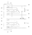
- the sole figure shows a circuit arrangement according to the invention.
- the single figure does not show a waste heat boiler 10 Combined power plant shown in more detail, in which in two separate pipe systems 12, 14 steam is generated due to the release of the waste heat of the exhaust gas Gas turbine of the combined cycle power plant, not shown in detail, which flows into the waste heat boiler 10 at the inlet 16 and at the outlet 18 leaves the waste heat boiler 10 to an exhaust gas fireplace to flow in.
- the waste heat boiler 10 designed so that the two mentioned Pipe systems 12, 14 for separate steam generation can be connected.
- This is the flue gas inlet 16 adjacent systems provided as high pressure system, while that is in the direction of flow of the flue gas behind it located piping systems 14 as a low pressure system is executed.
- the HD piping system 12 has an HD feed water line 20, which water to be evaporated one in the waste heat boiler 10 arranged economizer 22 feeds.
- the economiser 22 is on the output side with one also in the waste heat boiler arranged evaporator 24 connected, the outlet side to one in the waste heat boiler 10 immediately a superheater arranged in the vicinity of the flue gas inlet 16 26 connects, the outlet line 28 to one here Steam turbine not shown is guided.
- an LP feed water line 30 is provided which leads to a Economiser 32 is guided, the output side with a Evaporator circuit 34 is connected, the outlet side leads to a superheater 36, whose outlet line 38 a low-pressure steam turbine, also not shown leads.
- the low pressure system according to the arrows I or II to feed in this way the start-up process on the one hand to accelerate and so excessive Avoid heat pollution of the environment.
- the diversion station is pressure-cooled and closes automatically as soon as a certain one Pressure level reached on the LP side.
Landscapes
- Engineering & Computer Science (AREA)
- Chemical & Material Sciences (AREA)
- Combustion & Propulsion (AREA)
- Mechanical Engineering (AREA)
- General Engineering & Computer Science (AREA)
- Control Of Steam Boilers And Waste-Gas Boilers (AREA)
- Engine Equipment That Uses Special Cycles (AREA)
- Waste-Gas Treatment And Other Accessory Devices For Furnaces (AREA)
Claims (6)
- Procédé de démarrage d'une chaudière de récupération (10) dans une centrale combinée force-chaleur à turbine à gaz, avec deux circuits de pression (12, 14) avec des niveaux de pression différents qui présentent chacun une branche surchauffeur, la vapeur produite étant utilisée pour faire fonctionner une turbine à vapeur seulement lorsque des paramètres prédéterminés de pression et de température sont atteints, comportant les étapes suivantes:pendant la phase de montée en température, lors du démarrage, les circuits (12, 14) haute pression et basse pression sont connectés l'un à l'autre à l'aide d'un bloc de dérivation de telle sorte que la vapeur sortant du surchauffeur (26) du circuit (12) haute pression passe d'abord dans la branche surchauffeur du circuit (14) basse pression et, lorsque le circuit (14) se réchauffe s'écoule dans une turbine basse pression;lorsqu'un niveau de pression prédéterminé est atteint dans le circuit (14) basse pression, le bloc de dérivation (40) est fermé.
- Procédé selon la revendication 1, caractérisé par le fait que la chaleur de la vapeur du circuit (12) haute pression est apportée au circuit (14) basse pression par l'intermédiaire d'échangeurs.
- Procédé selon la revendication 1, caractérisé par le fait que la chaleur de la vapeur du circuit (12) haute pression est apportée au circuit (14) basse pression par injection dans le circuit (14).
- Installation pour la mise en oeuvre du procédé selon l'une des revendications précédentes, avec une chaudière de récupération (10), avec au moins deux circuits de pression (12, 14) avec des niveaux de pression différents, à chacun desquels sont associés, dans la chaudière de récupération, respectivement un vaporiseur (24, 34) et un surchauffeur (26, 36), chaque circuit de pression comportant une conduite d'eau d'alimentation (20, 30) séparée et une conduite de sortie (28, 38) séparée menant de la chaudière de récupération (10) à une turbine à vapeur et avec un bloc de dérivation (40) pour connecter les deux conduites de sortie (28, 38), à l'aide duquel les deux circuits de pression (12, 14) peuvent être connectés l'un à l'autre de telle sorte que la vapeur provenant du surchauffeur (26) du circuit (12) haute pression, pendant la phase de montée en température lors du démarrage, circule tout d'abord dans la branche réchauffeur du circuit (14) basse pression et lorsque le circuit (14) se réchauffe s'écoule dans une turbine basse pression.
- Installation selon la revendication 4, caractérisée par le fait que le bloc de dérivation (40) est agencé en dispositif de sécurité faisant office de moyen de remplacement d'une soupape de sécurité pour le circuit (12) haute pression.
- Installation selon la revendication 4 ou 5, caractérisée par le fait que chaque circuit (12, 14) comporte un économiseur (22, 32) dont la sortie débouche dans le circuit de vaporiseur (24, 34) concerné.
Applications Claiming Priority (2)
| Application Number | Priority Date | Filing Date | Title |
|---|---|---|---|
| DE4342002 | 1993-12-09 | ||
| DE4342002A DE4342002A1 (de) | 1993-12-09 | 1993-12-09 | Anfahren eines Abhitzekessels mit wenigstens zwei getrennten Drucksystemen |
Publications (2)
| Publication Number | Publication Date |
|---|---|
| EP0657627A1 EP0657627A1 (fr) | 1995-06-14 |
| EP0657627B1 true EP0657627B1 (fr) | 1998-08-19 |
Family
ID=6504580
Family Applications (1)
| Application Number | Title | Priority Date | Filing Date |
|---|---|---|---|
| EP94119098A Expired - Lifetime EP0657627B1 (fr) | 1993-12-09 | 1994-12-03 | Procédé et arrangement pour le mise en marche d'une chaudière de récupération avec au moins deux systèmes de pression séparés |
Country Status (5)
| Country | Link |
|---|---|
| EP (1) | EP0657627B1 (fr) |
| JP (1) | JPH07217803A (fr) |
| CN (1) | CN1109957A (fr) |
| AT (1) | ATE169988T1 (fr) |
| DE (2) | DE4342002A1 (fr) |
Families Citing this family (5)
| Publication number | Priority date | Publication date | Assignee | Title |
|---|---|---|---|---|
| DE19648642B4 (de) * | 1996-11-25 | 2005-06-23 | Alstom | Reinigung des Wasser-Dampfkreislaufs in einem Zwangsdurchlaufdampferzeuger |
| EP2224164A1 (fr) * | 2008-11-13 | 2010-09-01 | Siemens Aktiengesellschaft | Procédé destiné au fonctionnement d'un générateur de vapeur à récupération de chaleur |
| DE102010041903B4 (de) * | 2010-10-04 | 2017-03-09 | Siemens Aktiengesellschaft | Durchlaufdampferzeuger mit integriertem Zwischenüberhitzer |
| CN110513165B (zh) * | 2019-09-04 | 2021-11-16 | 深圳万润综合能源有限公司 | 一种冷热电三联供分布式能源系统 |
| TR2021009618A1 (tr) * | 2021-06-11 | 2022-10-21 | Repg Enerji Sistemleri Sanayi Ve Ticaret Anonim Sirketi | Bi̇r atik isi enerji̇ üreti̇m ve kontrol si̇stemi̇ |
Family Cites Families (7)
| Publication number | Priority date | Publication date | Assignee | Title |
|---|---|---|---|---|
| JPS5532916A (en) * | 1978-08-25 | 1980-03-07 | Hitachi Ltd | Method of making temperature of steam turbine metal of combined plant constant and its device |
| CH632331A5 (de) * | 1978-10-03 | 1982-09-30 | Sulzer Ag | Verfahren zum anfahren eines zwanglaufdampferzeugers. |
| SU840552A1 (ru) * | 1979-09-10 | 1981-06-23 | Войсковая часть 27177 | Котел-утилизатор |
| US4501233A (en) * | 1982-04-24 | 1985-02-26 | Babcock-Hitachi Kabushiki Kaisha | Heat recovery steam generator |
| JPS62276205A (ja) * | 1986-05-26 | 1987-12-01 | Toshiba Corp | 複合サイクルプラントの蒸気圧力制御装置 |
| JPH0650068B2 (ja) * | 1988-12-09 | 1994-06-29 | 株式会社日立製作所 | ガスタービンの起動方法 |
| JP2593578B2 (ja) * | 1990-10-18 | 1997-03-26 | 株式会社東芝 | コンバインドサイクル発電プラント |
-
1993
- 1993-12-09 DE DE4342002A patent/DE4342002A1/de not_active Ceased
-
1994
- 1994-12-03 AT AT94119098T patent/ATE169988T1/de active
- 1994-12-03 EP EP94119098A patent/EP0657627B1/fr not_active Expired - Lifetime
- 1994-12-03 DE DE59406728T patent/DE59406728D1/de not_active Expired - Lifetime
- 1994-12-08 CN CN94112922A patent/CN1109957A/zh active Pending
- 1994-12-09 JP JP6306686A patent/JPH07217803A/ja active Pending
Also Published As
| Publication number | Publication date |
|---|---|
| JPH07217803A (ja) | 1995-08-18 |
| ATE169988T1 (de) | 1998-09-15 |
| DE59406728D1 (de) | 1998-09-24 |
| CN1109957A (zh) | 1995-10-11 |
| DE4342002A1 (de) | 1995-06-14 |
| EP0657627A1 (fr) | 1995-06-14 |
Similar Documents
| Publication | Publication Date | Title |
|---|---|---|
| DE69916099T2 (de) | Kombikraftwerk mit verbesserter kühlung und betriebsverfahren dazu | |
| EP0819209B1 (fr) | Procede de fonctionnement d'un generateur de vapeur a recuperation de chaleur, et generateur de vapeur a recuperation de chaleur fonctionnant selon ce procede | |
| DE10041413B4 (de) | Verfahren zum Betrieb einer Kraftwerksanlage | |
| DE19513285B4 (de) | Turbinen-Antrieb für Kesselspeisepumpe / Speisewasser-Leitungssystem | |
| EP0523467A1 (fr) | Procédé pour opérer une installation à turbines à gaz et à vapeur et installation pour la mise en oeuvre du procédé | |
| CH623888A5 (fr) | ||
| EP3420202B1 (fr) | Recirculation de condensat | |
| DE2311066A1 (de) | Dampferzeuger fuer ungefeuerte kraftanlage | |
| DE102018123663A1 (de) | Brennstoffvorwärmsystem für eine Verbrennungsgasturbine | |
| EP2359058A2 (fr) | Procédé de fonctionnement d'un générateur de vapeur à récupération de chaleur | |
| EP1105624B1 (fr) | Installation de turbine a gaz et a vapeur | |
| EP0515911A1 (fr) | Méthode pour opérer une installation à turbines à gaz et à vapeur et une installation correspondante | |
| EP1320663A1 (fr) | Procede et dispositif pour rechauffer et purger des conduites d'amenee de vapeur raccordees a des turbines a vapeur | |
| EP0523466A1 (fr) | Procédé de fonctionnement d'une installation à turbines à gaz et à vapeur et installation pour la mise en oeuvre du procédé | |
| WO2010034659A2 (fr) | Centrale à vapeur pour produire de l'énergie électrique | |
| DE10155508C5 (de) | Verfahren und Vorrichtung zur Erzeugung von elektrischer Energie | |
| EP1425079B1 (fr) | Procede et dispositif de degazage thermique de la substance active d'un processus a deux phases | |
| DE4300192C2 (de) | Verfahren zum Betrieb von mindestens zwei miteinander verknüpften Abhitzeprozessen und Dampferzeugungsanlage zur Durchführung des Verfahrens | |
| EP3620620A1 (fr) | Recirculation des gaz d'échappement dans des installations de turbines à gaz et à vapeur | |
| EP0657627A1 (fr) | Mise en marche d'une chaudière de récupération avec au moins deux systèmes de pression séparés | |
| EP1801363A1 (fr) | Centrale électrique | |
| DE4409811C1 (de) | Verfahren zum Betreiben eines Abhitzedampferzeugers sowie danach arbeitender Abhitzedampferzeuger | |
| DE2512774A1 (de) | Gasturbinen-heizkraftwerk | |
| DE1228623B (de) | Dampfkraftanlage mit Zwanglaufdampferzeuger und Zwischenueberhitzer | |
| DE10004187C5 (de) | Verfahren zum Betreiben einer Gas- und Dampfturbinenanlage sowie danach arbeitende Anlage |
Legal Events
| Date | Code | Title | Description |
|---|---|---|---|
| PUAI | Public reference made under article 153(3) epc to a published international application that has entered the european phase |
Free format text: ORIGINAL CODE: 0009012 |
|
| AK | Designated contracting states |
Kind code of ref document: A1 Designated state(s): AT DE FR GB IT |
|
| 17P | Request for examination filed |
Effective date: 19950724 |
|
| 17Q | First examination report despatched |
Effective date: 19960228 |
|
| GRAG | Despatch of communication of intention to grant |
Free format text: ORIGINAL CODE: EPIDOS AGRA |
|
| GRAG | Despatch of communication of intention to grant |
Free format text: ORIGINAL CODE: EPIDOS AGRA |
|
| GRAH | Despatch of communication of intention to grant a patent |
Free format text: ORIGINAL CODE: EPIDOS IGRA |
|
| GRAH | Despatch of communication of intention to grant a patent |
Free format text: ORIGINAL CODE: EPIDOS IGRA |
|
| GRAA | (expected) grant |
Free format text: ORIGINAL CODE: 0009210 |
|
| AK | Designated contracting states |
Kind code of ref document: B1 Designated state(s): AT DE FR GB IT |
|
| REF | Corresponds to: |
Ref document number: 169988 Country of ref document: AT Date of ref document: 19980915 Kind code of ref document: T |
|
| REF | Corresponds to: |
Ref document number: 59406728 Country of ref document: DE Date of ref document: 19980924 |
|
| PGFP | Annual fee paid to national office [announced via postgrant information from national office to epo] |
Ref country code: FR Payment date: 19980925 Year of fee payment: 5 |
|
| PGFP | Annual fee paid to national office [announced via postgrant information from national office to epo] |
Ref country code: GB Payment date: 19980928 Year of fee payment: 5 |
|
| ET | Fr: translation filed | ||
| PGFP | Annual fee paid to national office [announced via postgrant information from national office to epo] |
Ref country code: AT Payment date: 19981023 Year of fee payment: 5 |
|
| GBT | Gb: translation of ep patent filed (gb section 77(6)(a)/1977) |
Effective date: 19981008 |
|
| PLBE | No opposition filed within time limit |
Free format text: ORIGINAL CODE: 0009261 |
|
| STAA | Information on the status of an ep patent application or granted ep patent |
Free format text: STATUS: NO OPPOSITION FILED WITHIN TIME LIMIT |
|
| 26N | No opposition filed | ||
| PG25 | Lapsed in a contracting state [announced via postgrant information from national office to epo] |
Ref country code: GB Free format text: LAPSE BECAUSE OF NON-PAYMENT OF DUE FEES Effective date: 19991203 Ref country code: AT Free format text: LAPSE BECAUSE OF NON-PAYMENT OF DUE FEES Effective date: 19991203 |
|
| GBPC | Gb: european patent ceased through non-payment of renewal fee |
Effective date: 19991203 |
|
| PG25 | Lapsed in a contracting state [announced via postgrant information from national office to epo] |
Ref country code: FR Free format text: LAPSE BECAUSE OF NON-PAYMENT OF DUE FEES Effective date: 20000831 |
|
| REG | Reference to a national code |
Ref country code: FR Ref legal event code: ST |
|
| PG25 | Lapsed in a contracting state [announced via postgrant information from national office to epo] |
Ref country code: IT Free format text: LAPSE BECAUSE OF NON-PAYMENT OF DUE FEES;WARNING: LAPSES OF ITALIAN PATENTS WITH EFFECTIVE DATE BEFORE 2007 MAY HAVE OCCURRED AT ANY TIME BEFORE 2007. THE CORRECT EFFECTIVE DATE MAY BE DIFFERENT FROM THE ONE RECORDED. Effective date: 20051203 |
|
| PGFP | Annual fee paid to national office [announced via postgrant information from national office to epo] |
Ref country code: DE Payment date: 20051212 Year of fee payment: 12 |
|
| PG25 | Lapsed in a contracting state [announced via postgrant information from national office to epo] |
Ref country code: DE Free format text: LAPSE BECAUSE OF THE APPLICANT RENOUNCES Effective date: 20060626 |