EP0657633A1 - Système de refroidissement par évaporation avec de remblayage partiel - Google Patents
Système de refroidissement par évaporation avec de remblayage partiel Download PDFInfo
- Publication number
- EP0657633A1 EP0657633A1 EP94117995A EP94117995A EP0657633A1 EP 0657633 A1 EP0657633 A1 EP 0657633A1 EP 94117995 A EP94117995 A EP 94117995A EP 94117995 A EP94117995 A EP 94117995A EP 0657633 A1 EP0657633 A1 EP 0657633A1
- Authority
- EP
- European Patent Office
- Prior art keywords
- cooling system
- storage container
- condenser
- evaporative cooling
- condensate
- Prior art date
- Legal status (The legal status is an assumption and is not a legal conclusion. Google has not performed a legal analysis and makes no representation as to the accuracy of the status listed.)
- Granted
Links
Images



Classifications
-
- F—MECHANICAL ENGINEERING; LIGHTING; HEATING; WEAPONS; BLASTING
- F28—HEAT EXCHANGE IN GENERAL
- F28F—DETAILS OF HEAT-EXCHANGE AND HEAT-TRANSFER APPARATUS, OF GENERAL APPLICATION
- F28F9/00—Casings; Header boxes; Auxiliary supports for elements; Auxiliary members within casings
- F28F9/02—Header boxes; End plates
- F28F9/0231—Header boxes having an expansion chamber
-
- F—MECHANICAL ENGINEERING; LIGHTING; HEATING; WEAPONS; BLASTING
- F01—MACHINES OR ENGINES IN GENERAL; ENGINE PLANTS IN GENERAL; STEAM ENGINES
- F01P—COOLING OF MACHINES OR ENGINES IN GENERAL; COOLING OF INTERNAL-COMBUSTION ENGINES
- F01P11/00—Component parts, details, or accessories not provided for in, or of interest apart from, groups F01P1/00 - F01P9/00
- F01P11/02—Liquid-coolant filling, overflow, venting, or draining devices
- F01P11/029—Expansion reservoirs
-
- F—MECHANICAL ENGINEERING; LIGHTING; HEATING; WEAPONS; BLASTING
- F01—MACHINES OR ENGINES IN GENERAL; ENGINE PLANTS IN GENERAL; STEAM ENGINES
- F01P—COOLING OF MACHINES OR ENGINES IN GENERAL; COOLING OF INTERNAL-COMBUSTION ENGINES
- F01P3/00—Liquid cooling
- F01P3/22—Liquid cooling characterised by evaporation and condensation of coolant in closed cycles; characterised by the coolant reaching higher temperatures than normal atmospheric boiling-point
- F01P3/2271—Closed cycles with separator and liquid return
-
- F—MECHANICAL ENGINEERING; LIGHTING; HEATING; WEAPONS; BLASTING
- F01—MACHINES OR ENGINES IN GENERAL; ENGINE PLANTS IN GENERAL; STEAM ENGINES
- F01P—COOLING OF MACHINES OR ENGINES IN GENERAL; COOLING OF INTERNAL-COMBUSTION ENGINES
- F01P3/00—Liquid cooling
- F01P3/22—Liquid cooling characterised by evaporation and condensation of coolant in closed cycles; characterised by the coolant reaching higher temperatures than normal atmospheric boiling-point
- F01P2003/2214—Condensers
- F01P2003/2221—Condensers of the horizontal type
Definitions
- the invention relates to a partially flooded evaporative cooling system according to the preamble of claim 1.
- Such a system is known for example from DE-A 40 01 208.
- the reservoir is located below the condenser. This means that a minimum overall height is specified, which cannot always be ensured with today's vehicles.
- the object of the present invention is to remedy this situation and to propose an arrangement and configuration for a storage container for liquid condensate in a generic cooling system which is simple in construction and has the least possible outlay for filling and checking the fill level.
- This object is achieved by the characterizing features of claim 1.
- the length of the ventilation line determines the filling level when the internal combustion engine is cold. As a result, the system can be very easily adapted to different cooling system sizes by simply shortening or lengthening the ventilation line.
- Claim 2 prevents in particular that excessive steam entry into the expansion tank occurs when the condenser is fully charged with steam.
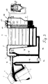
- FIG. 1 shows an internal combustion engine 1 with an evaporative cooling system. It consists of the cooling rooms 2 in the crankcase 3 and the cooling rooms 4 in the cylinder head 5.
- a flow line 6 leads from the cylinder head 5 to a steam separator 7.
- the steam separator 7 is connected to the inlet connection 8 of a cross-flow condenser 9. Accordingly, the condenser 9 has a lateral inlet collecting box 10 and an outlet collecting box 11.
- a connecting line 12 connects the two header boxes 10 and 11 at their lower end and leads via a return line 13 to a condensate feed pump 14.
- the condensate feed pump 14 conveys the liquid condensate via the line 16 into the lower part of the cold rooms 2 in the crankcase 3.
- the reservoir 17 is arranged in one piece with it. At its lower end there is a passage opening 18 which connects the storage container 17 to the condensate collection box 11.
- a ventilation line 21 branches off from the storage container 17 via a throttle point 20 and runs in the condensate collection box 11 to level I.
- the beginning of the ventilation line 21 in area 19 lies at a level II, which below the lower edge of the inlet connector 8 runs into the condenser 9.
- the storage container 17 has a closure lid 22, which serves to fill the liquid condensate into the storage container. Furthermore, a connecting line 23 branches off from the storage container 17 to the surroundings. So that no dirt from the environment enters this connecting line 23, it has an appropriately designed opening and / or a molecular sieve at its free end. Furthermore, the free end of the connecting line 23 is arranged so that it can be cooled by the wind. This ensures that almost no coolant can escape even in the vapor state.
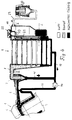
- FIG 2 the system of Figure 1 is shown after an initial filling with the coolant pump stopped.
- the closure cover 22 is opened and condensate is filled in until the condensate in the storage container 17 is above level II.
- the ventilation line 21 is then completely filled and the condenser 9 with its collecting boxes 10 and 11 is partially filled with condensate.
- the collecting line 12 and the condensate return line 13 are completely filled with condensate.
- the condensate in lines 15 and 16 is at the same filling level as the condenser 9.
- the filling level in line 16 results from the fact that the condensate feed pump 14 does not completely block in the rest position, but rather only represents an increased flow resistance.
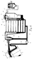
- the arrangement according to FIG. 3 arises when the one filled according to FIG. 2 and through the closure cover 22 closed system, the coolant delivery pump 14 is switched on.
- the condensate is pumped into the cold rooms 2 and 4 and into the flow line 6 to the steam separator 7. From the steam separator 7, it runs through the line 15 to the condensate return line 13 and thus to the suction side of the condensate feed pump 14. This process displaces the air in the previously unfilled spaces and can escape via the ventilation line 21 and the connecting line 23. As a result, the condensate level in the storage container 17 simultaneously drops to level I, which corresponds to the cold filling level when the internal combustion engine is stopped.
- liquid condensate i.e. coolant
- the state in FIG. 4 arises in the cooling system according to FIG. 2 when the internal combustion engine has been started and is operating in the part-load range, that is to say releases heat to the liquid condensate, so that first vapor bubbles can form in the cooling rooms 2 and 4.
- the running condensate feed pump ensures that the cooling chambers of the internal combustion engine are constantly supplied with liquid condensate. Excess condensate and steam which forms are mixed with liquid condensate are conveyed via the feed line 6 to the steam separator 7, where the steam separates from the liquid coolant. The steam then passes into the inlet port 8 of the condenser 9, where it can condense.
- the condensate level in the condenser and its collecting tanks drops, so that the ventilation line 21 at its lower end no longer immersed in the condensate.
- the air displaced by the steam can escape from the condenser into the storage container 17 and from there via the connecting line 23 to the outside. Due to the increasing pressure in the system, the condensate level in the storage container 17 increases slightly above the filling level I.
- Decreasing engine load also means decreasing vapor bubble formation and increase in the liquid condensate. This also lowers the pressure in the cooling system, so that ambient air can be supplied via the connecting line 23, the reservoir 17, the throttle 20 and the ventilation line 21. This prevents negative pressure in the system. With this load condition, the condensate level in the storage tank drops below fill level I.
Landscapes
- Engineering & Computer Science (AREA)
- Mechanical Engineering (AREA)
- General Engineering & Computer Science (AREA)
- Chemical & Material Sciences (AREA)
- Combustion & Propulsion (AREA)
- Physics & Mathematics (AREA)
- Thermal Sciences (AREA)
- Lubrication Details And Ventilation Of Internal Combustion Engines (AREA)
- Filling Or Discharging Of Gas Storage Vessels (AREA)
- Heat-Exchange Devices With Radiators And Conduit Assemblies (AREA)
Applications Claiming Priority (2)
| Application Number | Priority Date | Filing Date | Title |
|---|---|---|---|
| DE4341927A DE4341927A1 (de) | 1993-12-09 | 1993-12-09 | Teilgeflutetes Verdampfungskühlsystem |
| DE4341927 | 1993-12-09 |
Publications (2)
| Publication Number | Publication Date |
|---|---|
| EP0657633A1 true EP0657633A1 (fr) | 1995-06-14 |
| EP0657633B1 EP0657633B1 (fr) | 1997-08-13 |
Family
ID=6504526
Family Applications (1)
| Application Number | Title | Priority Date | Filing Date |
|---|---|---|---|
| EP94117995A Expired - Lifetime EP0657633B1 (fr) | 1993-12-09 | 1994-11-15 | Système de refroidissement par évaporation avec de remblayage partiel |
Country Status (2)
| Country | Link |
|---|---|
| EP (1) | EP0657633B1 (fr) |
| DE (2) | DE4341927A1 (fr) |
Cited By (1)
| Publication number | Priority date | Publication date | Assignee | Title |
|---|---|---|---|---|
| US7791885B2 (en) | 2008-05-14 | 2010-09-07 | Abb Research Ltd | Two-phase cooling circuit |
Families Citing this family (1)
| Publication number | Priority date | Publication date | Assignee | Title |
|---|---|---|---|---|
| DE102008033024B4 (de) | 2008-07-14 | 2010-06-10 | Iav Gmbh Ingenieurgesellschaft Auto Und Verkehr | Verfahren zur Entlüftung eines Kühlmittelkreislaufes einer Brennkraftmaschine und Kühlmittelkreislauf für eine Brennkraftmaschine |
Citations (5)
| Publication number | Priority date | Publication date | Assignee | Title |
|---|---|---|---|---|
| FR2532740A1 (fr) * | 1982-09-03 | 1984-03-09 | Valeo | Echangeur de chaleur, en particulier pour circuit de refroidissement d'un moteur diesel |
| WO1986003554A1 (fr) * | 1984-12-05 | 1986-06-19 | Bayerische Motoren Werke Aktiengesellschaft | Radiateur en matiere plastique pour les systemes de refroidissement a ecoulement transversal des moteurs a combustion interne |
| EP0496942A1 (fr) * | 1991-01-31 | 1992-08-05 | Firma Carl Freudenberg | Moteur à combustion interne refroidi par ébullition |
| EP0571248A1 (fr) * | 1992-05-19 | 1993-11-24 | Valeo Thermique Moteur | Dispositif de refroidissement d'un moteur thermique comprenant un condenseur |
| DE4231846A1 (de) * | 1992-09-23 | 1994-03-24 | Bayerische Motoren Werke Ag | Verdampfungskühlsystem für eine Brennkraftmaschine |
Family Cites Families (5)
| Publication number | Priority date | Publication date | Assignee | Title |
|---|---|---|---|---|
| DE2033960A1 (de) * | 1970-07-08 | 1972-01-20 | Teledyne Industries, Ine , Los Ange les,Cahf (VStA) | Mehrstufiges geschichtetes Dampfkuhl system mit geschlossenem Kreislauf fur Brennkraftmaschinen |
| DE4001208A1 (de) * | 1990-01-17 | 1991-07-18 | Bayerische Motoren Werke Ag | Verdampfungskuehlsystem fuer eine fluessigkeitsgekuehlte brennkraftmaschine |
| FR2674289B1 (fr) * | 1991-03-20 | 1995-02-17 | Valeo Thermique Moteur Sa | Dispositif de refroidissement en mode diphasique pour moteur a combustion interne. |
| DE4122551A1 (de) * | 1991-07-08 | 1993-01-14 | Bayerische Motoren Werke Ag | Entlueftungsvorrichtung fuer verdampfungskuehlsysteme |
| DE4222913C2 (de) * | 1992-07-11 | 1996-02-01 | Bayerische Motoren Werke Ag | Verdampfungskühlsystem für eine Brennkraftmaschine |
-
1993
- 1993-12-09 DE DE4341927A patent/DE4341927A1/de not_active Withdrawn
-
1994
- 1994-11-15 DE DE59403722T patent/DE59403722D1/de not_active Expired - Fee Related
- 1994-11-15 EP EP94117995A patent/EP0657633B1/fr not_active Expired - Lifetime
Patent Citations (5)
| Publication number | Priority date | Publication date | Assignee | Title |
|---|---|---|---|---|
| FR2532740A1 (fr) * | 1982-09-03 | 1984-03-09 | Valeo | Echangeur de chaleur, en particulier pour circuit de refroidissement d'un moteur diesel |
| WO1986003554A1 (fr) * | 1984-12-05 | 1986-06-19 | Bayerische Motoren Werke Aktiengesellschaft | Radiateur en matiere plastique pour les systemes de refroidissement a ecoulement transversal des moteurs a combustion interne |
| EP0496942A1 (fr) * | 1991-01-31 | 1992-08-05 | Firma Carl Freudenberg | Moteur à combustion interne refroidi par ébullition |
| EP0571248A1 (fr) * | 1992-05-19 | 1993-11-24 | Valeo Thermique Moteur | Dispositif de refroidissement d'un moteur thermique comprenant un condenseur |
| DE4231846A1 (de) * | 1992-09-23 | 1994-03-24 | Bayerische Motoren Werke Ag | Verdampfungskühlsystem für eine Brennkraftmaschine |
Cited By (1)
| Publication number | Priority date | Publication date | Assignee | Title |
|---|---|---|---|---|
| US7791885B2 (en) | 2008-05-14 | 2010-09-07 | Abb Research Ltd | Two-phase cooling circuit |
Also Published As
| Publication number | Publication date |
|---|---|
| EP0657633B1 (fr) | 1997-08-13 |
| DE59403722D1 (de) | 1997-09-18 |
| DE4341927A1 (de) | 1995-06-14 |
Similar Documents
| Publication | Publication Date | Title |
|---|---|---|
| DE102008008466B4 (de) | Fluidspeichervorrichtung und damit aususgestaltetes Getriebe | |
| DE102008060088B4 (de) | Ausgleichsbehälter für eine Kühlanlage | |
| CH642429A5 (de) | Hydraulische vorrichtung zum betaetigen von gaswechselventilen. | |
| DE4037803A1 (de) | Schmier- und/oder kuehloelversorgung fuer eine maschine, insbesondere eine brennkraftmaschine | |
| DE10310179B4 (de) | Ölauffangvorrichtung für eine Brennkraftmaschine, insbesondere für einen Boxermotor | |
| DE112023005821T5 (de) | Integrierter Neben-Kraftstofftank für Fahrzeuge | |
| DE3533094A1 (de) | Ausgleichsbehaelter fuer kuehlfluessigkeit | |
| DE3532349C2 (fr) | ||
| DE102016116542B4 (de) | Ansaugkrümmer für Fahrzeuge mit vereinigtem Gasstromkanal | |
| DE10238237A1 (de) | Kammerentleerungseinrichtung | |
| EP0693617B1 (fr) | Radiateur à courant transversal avec purge d'air | |
| EP0657633B1 (fr) | Système de refroidissement par évaporation avec de remblayage partiel | |
| DE102005035731A1 (de) | Brennkraftmaschine und Schmiersystem dafür | |
| EP0979747B1 (fr) | Dispositif de remplissage | |
| WO2017178614A1 (fr) | Système d'alimentation en huile indépendant de la position, système d'acheminement d'huile indépendant de la position et système d'huile indépendant de la position pour un moteur à combustion interne | |
| EP0393654B1 (fr) | Système de refroidissement | |
| DE4311470A1 (de) | Be- und Entlüftungseinrichtung eines Fahrzeug-Kraftstofftanks | |
| DE102004045441B4 (de) | Vorrichtung zur Versorgung eines Antriebs mit flüssigem Schmiermittel | |
| DE4224862C2 (de) | Verdampfungskühlsystem für eine Brennkraftmaschine | |
| DE4342295A1 (de) | Verdampfungskühlsystem für eine Brennkraftmaschine | |
| DE102014001965B4 (de) | Ölbehälter einer Brennkraftmaschine | |
| DE102020102882A1 (de) | Brennkraftmaschine mit Schmiermittelversorgung | |
| EP1179660B1 (fr) | Vase d'expansion pour un système de refroidissement d'un moteur à combustion interne, notamment pour véhicules | |
| DE102005053815A1 (de) | Entlüftungseinheit für das System zum Be- und Entlüften eines Kraftstoffbehälters | |
| DE4317788C2 (de) | Verdampfungskühlsystem für eine Brennkraftmaschine |
Legal Events
| Date | Code | Title | Description |
|---|---|---|---|
| PUAI | Public reference made under article 153(3) epc to a published international application that has entered the european phase |
Free format text: ORIGINAL CODE: 0009012 |
|
| AK | Designated contracting states |
Kind code of ref document: A1 Designated state(s): DE FR GB IT |
|
| 17P | Request for examination filed |
Effective date: 19950627 |
|
| GRAG | Despatch of communication of intention to grant |
Free format text: ORIGINAL CODE: EPIDOS AGRA |
|
| 17Q | First examination report despatched |
Effective date: 19961104 |
|
| GRAH | Despatch of communication of intention to grant a patent |
Free format text: ORIGINAL CODE: EPIDOS IGRA |
|
| GRAH | Despatch of communication of intention to grant a patent |
Free format text: ORIGINAL CODE: EPIDOS IGRA |
|
| GRAA | (expected) grant |
Free format text: ORIGINAL CODE: 0009210 |
|
| AK | Designated contracting states |
Kind code of ref document: B1 Designated state(s): DE FR GB IT |
|
| GBT | Gb: translation of ep patent filed (gb section 77(6)(a)/1977) |
Effective date: 19970821 |
|
| REF | Corresponds to: |
Ref document number: 59403722 Country of ref document: DE Date of ref document: 19970918 |
|
| ET | Fr: translation filed | ||
| ITF | It: translation for a ep patent filed | ||
| PLBE | No opposition filed within time limit |
Free format text: ORIGINAL CODE: 0009261 |
|
| STAA | Information on the status of an ep patent application or granted ep patent |
Free format text: STATUS: NO OPPOSITION FILED WITHIN TIME LIMIT |
|
| 26N | No opposition filed | ||
| PGFP | Annual fee paid to national office [announced via postgrant information from national office to epo] |
Ref country code: GB Payment date: 19981109 Year of fee payment: 5 |
|
| PGFP | Annual fee paid to national office [announced via postgrant information from national office to epo] |
Ref country code: DE Payment date: 19981110 Year of fee payment: 5 |
|
| PGFP | Annual fee paid to national office [announced via postgrant information from national office to epo] |
Ref country code: FR Payment date: 19981130 Year of fee payment: 5 |
|
| PG25 | Lapsed in a contracting state [announced via postgrant information from national office to epo] |
Ref country code: GB Free format text: LAPSE BECAUSE OF NON-PAYMENT OF DUE FEES Effective date: 19991115 |
|
| GBPC | Gb: european patent ceased through non-payment of renewal fee |
Effective date: 19991115 |
|
| PG25 | Lapsed in a contracting state [announced via postgrant information from national office to epo] |
Ref country code: FR Free format text: LAPSE BECAUSE OF NON-PAYMENT OF DUE FEES Effective date: 20000731 |
|
| PG25 | Lapsed in a contracting state [announced via postgrant information from national office to epo] |
Ref country code: DE Free format text: LAPSE BECAUSE OF NON-PAYMENT OF DUE FEES Effective date: 20000901 |
|
| REG | Reference to a national code |
Ref country code: FR Ref legal event code: ST |
|
| PG25 | Lapsed in a contracting state [announced via postgrant information from national office to epo] |
Ref country code: IT Free format text: LAPSE BECAUSE OF NON-PAYMENT OF DUE FEES;WARNING: LAPSES OF ITALIAN PATENTS WITH EFFECTIVE DATE BEFORE 2007 MAY HAVE OCCURRED AT ANY TIME BEFORE 2007. THE CORRECT EFFECTIVE DATE MAY BE DIFFERENT FROM THE ONE RECORDED. Effective date: 20051115 |