EP0657664A1 - Nockenmechanismus - Google Patents
Nockenmechanismus Download PDFInfo
- Publication number
- EP0657664A1 EP0657664A1 EP94117107A EP94117107A EP0657664A1 EP 0657664 A1 EP0657664 A1 EP 0657664A1 EP 94117107 A EP94117107 A EP 94117107A EP 94117107 A EP94117107 A EP 94117107A EP 0657664 A1 EP0657664 A1 EP 0657664A1
- Authority
- EP
- European Patent Office
- Prior art keywords
- turret
- cam
- rollers
- piston
- slider
- Prior art date
- Legal status (The legal status is an assumption and is not a legal conclusion. Google has not performed a legal analysis and makes no representation as to the accuracy of the status listed.)
- Withdrawn
Links
- 230000001133 acceleration Effects 0.000 claims description 21
- 238000006073 displacement reaction Methods 0.000 claims description 10
- 230000001131 transforming effect Effects 0.000 abstract 1
- 238000010586 diagram Methods 0.000 description 34
- 239000013598 vector Substances 0.000 description 15
- 230000001174 ascending effect Effects 0.000 description 11
- 230000035939 shock Effects 0.000 description 5
- 230000002093 peripheral effect Effects 0.000 description 4
- 238000000034 method Methods 0.000 description 3
- 230000000694 effects Effects 0.000 description 2
- 239000000470 constituent Substances 0.000 description 1
- 230000007246 mechanism Effects 0.000 description 1
- 238000005096 rolling process Methods 0.000 description 1
Images










Classifications
-
- F—MECHANICAL ENGINEERING; LIGHTING; HEATING; WEAPONS; BLASTING
- F16—ENGINEERING ELEMENTS AND UNITS; GENERAL MEASURES FOR PRODUCING AND MAINTAINING EFFECTIVE FUNCTIONING OF MACHINES OR INSTALLATIONS; THERMAL INSULATION IN GENERAL
- F16H—GEARING
- F16H27/00—Step-by-step mechanisms without freewheel members, e.g. Geneva drives
- F16H27/02—Step-by-step mechanisms without freewheel members, e.g. Geneva drives with at least one reciprocating or oscillating transmission member
-
- F—MECHANICAL ENGINEERING; LIGHTING; HEATING; WEAPONS; BLASTING
- F16—ENGINEERING ELEMENTS AND UNITS; GENERAL MEASURES FOR PRODUCING AND MAINTAINING EFFECTIVE FUNCTIONING OF MACHINES OR INSTALLATIONS; THERMAL INSULATION IN GENERAL
- F16H—GEARING
- F16H25/00—Gearings comprising primarily only cams, cam-followers and screw-and-nut mechanisms
- F16H25/08—Gearings comprising primarily only cams, cam-followers and screw-and-nut mechanisms for interconverting rotary motion and reciprocating motion
- F16H25/14—Gearings comprising primarily only cams, cam-followers and screw-and-nut mechanisms for interconverting rotary motion and reciprocating motion with reciprocation perpendicular to the axis of rotation
Definitions
- the present invention relates to cam apparatus and more particularly to a cam apparatus which converts expansion motion of a piston of a cylinder into rotational motion of a turret.
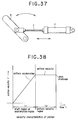
- Fig.38 being a graphical representation showing motion characteristics of the piston
- the cylinder a is started gradually within a uniform acceleration region of the piston c (this region will hereinafter be called a “start region” because the piston is about to start in this region.
- This region can also be called an “acceleration region” because the piston c is accelerated within the start region) and thereafter undergoes uniform velocity motion within a predetermined region (hereinafter, this region will be called a "uniform velocity region”) to collide with a cylinder case while being moved at a velocity so as to stop eventually.
- this region will be called a "uniform velocity region”
- the time that the piston collides with the cylinder case and stops will be referred to as "upon stoppage”. Accordingly, within the start region and upon stoppage, vibrations and shocks are caused, giving rise to a prior art problem that the follower member is prevented from smooth rotational motion at the beginning of its rotation and at the end of its rotation.
- the present invention intends to solve the above problem and it is an object of the invention to provide a cam apparatus which can apply constantly stable rotation to the turret standing for the follower member and can convert reciprocating motion into rotational motion without resort to complicated controlling.
- a cam apparatus comprises a rotatable turret serving as a follower member, a reciprocating engine serving as a motivator member for applying power to the turret, and a slider connected to a piston of the reciprocating engine to convert expansion motion of the piston into rotational motion of the turret and movable, together with the piston, relative to the turret.
- the slider is formed with flat portions at opposite end parts and a cam portion shaped to have a hill-valley form at a central part in a direction of travel of the slider, and the turret has a plurality of rollers arranged at the circumferential periphery of the turret and being in contact with the slider so as to roll in accordance with the movement of the slider.
- rollers prevent rotation of the turret when the flat portion of the slider is positioned by the expansion motion of the piston to confront the turret but rotation of the rollers cooperate with a travel or procession of the slider and the hill-valley shape of the cam portion to rotate the turret in a rotation direction conforming to the expansion motion of the piston when the cam portion of the slider is moved by the expansion motion of the piston to a position at which the cam portion comes into contact with the rollers of the turret, and the turret is confronted with the flat portion of the slider within the start region or upon stoppage of the reciprocating engine.
- the turret is prevented by the plurality of rollers from rotating when the turret is positioned at the flat portion of the slider and is confronted with the flat portion within the start region or upon stoppage of the piston, so that even when the turret receives shocks generated within the start region or upon stoppage, the rotation of the turret is never affected by the shocks since the turrent does not rotate inherently at the flat portion.
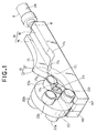
- Fig.1 is a perspective view showing the whole of a cam apparatus.
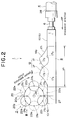
- Fig.2 is a side view showing the whole of the cam apparatus.
- Fig.3 is a diagram showing the cam apparatus as viewed in the direction of arrow III of Fig. 2.
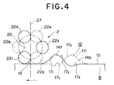
- Fig.4 is a diagram illustrative of operation to indicate a state in which a procession of a piston causes a slider to rotate a turret, showing a state of rotational phase 1 of the turret.
- Fig.5 is a diagram illustrative of operation to indicate a state in which a procession of the piston causes the slider to rotate the turret, showing a state of rotational phase 2 of the turret.
- Fig.6 is a diagram illustrative of operation to indicate a state in which a procession of the piston causes the slider to rotate the turret, showing a state of rotational phase 3 of the turret.
- Fig.7 is a diagram illustrative of operation to indicate a state in which a procession of the piston causes the slider to rotate the turret, showing a state of rotational phase 4 of the turret.
- Fig.8 is a diagram illustrative of operation to indicate a state in which a procession of the piston causes the slider to rotate the turret, showing a state of rotational phase 5 of the turret.
- Fig.9 is a diagram illustrative of operation to indicate a state in which a procession of the piston causes the slider to rotate the turret, showing a state of rotational phase 6 of the turret.
- Fig.10 is a diagram illustrative of operation to indicate a state in which a procession of the piston causes the slider to rotate the turret, showing a state of rotational phase 7 of the turret.
- Fig.11 is a diagram illustrative of operation to indicate a state in which a procession of the piston causes the slider to rotate the turret, showing a state of rotational phase 8 of the turret.
- Fig.12 is a diagram illustrative of operation to indicate a state in which a procession of the piston causes the slider to rotate the turret, showing a state of rotational phase 9 of the turret.
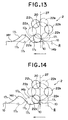
- Fig.13 is a diagram illustrative of operation to indicate a state in which a procession of the piston causes the slider to rotate the turret, showing a state of rotational phase 10 of the turret.
- Fig.14 is a diagram illstrative of operation to indicate a state in which a procession of the piston causes the slider to rotate the turret, showing a state of rotational phase 11 of the turret.
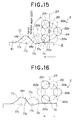
- Fig.15 is a diagram illustrative of operation to indicate a state in which a procession of the piston causes the slider to rotate the turret, showing a state of rotational phase 12 of the turret.
- Fig.16 is a diagram illustrative of operation to indicate a state in which a procession of the piston causes the slider to rotate the turret, showing a state of rotational phase 13 of the turret.
- Fig.17 is a graph showing the case where a rotary motion curve drawn or traced by the turret assumes a modified sine curve depending on the shape of a cam portion.
- Fig.18 is a circuit diagram showing the operation of an air cylinder.
- Fig.19 is a graph showing motion characteristics of piston based on a specified example.
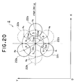
- Fig.20 a diagram useful to explain an XY coordinate system for determining the shape of the cam portion of the cam apparatus according to the invention and an origin line.
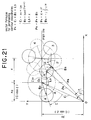
- Fig.21 is a vector diagram showing an example of determining locus of the center of a roller when six rollers are arranged at equal angular intervals.
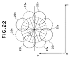
- Fig.22 is a diagram showing an example of the case where eight rollers are arranged at equal angular intervals.
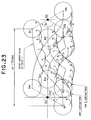
- Fig.23 is a diagram usful to explain a example of determining cam contours from the roller center loci.
- Fig.24 is a diagram useful to explain an example of determining a cam contour directly from a vector diagram showing the cam contour.
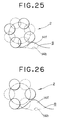
- Fig.25 is a diagram showing the case where the indexing angle of the turret is 45°.
- Fig.26 is a diagram showing the case where the indexing angle of the turret is 60°.
- Fig.27 is a diagram showing the case where the indexing angle of the turret is 90°.
- Fig.28 is a diagram showing the case where the indexing angle of the turret is 135°.
- Fig.29 is a diagram showing the case where the indexing angle of the turret is 180°.
- Fig.30 is a diagram showing the case where the indexing angle of the turret is 225°.
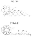
- Fig.31 is a diagram showing the case where the indexing angle of the turret is 240°.
- Fig.32 is a diagram showing the case where the indexing angle of the turret is 270°.
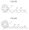
- Fig.33 is a diagram showing the case where the indexing angle of the turret is 300°.
- Fig.34 is a diagram showing the case where the indexing angle of the turret is 315°.
- Fig.35 is a diagram showing the case where the indexing angle of the turret is 360°.
- Fig.36 is a graph showing the case where the hill-valley shape of the cam portion causes the turret to draw a rotational motion curve which is a modified uniform velocity curve .
- Fig.37 is a diagram for explaining the prior art.
- Fig.38 is a graph showing motion characteristics of a general piston.
- a cam apparatus 1 has a turret 2 serving as a follower member which is rotatable clockwise or counterclockwise (hereinafter, the clockwise or counterclockwise rotational operation is simply referred to as "rotation"), a cylinder 4 in the form of an reciprocating engine serving as a motivator member for causing the turret 2 to rotate, and a slider 8 serving as a rectilinear motion cam which is connected to a piston 6 of the cylinder 4 to convert expansion motion of the piston 6 into rotation of the turret 2 and moves, together with the piston 6, in relation to the turret 2.
- These constituent members are mounted to a housing not shown.
- the slider 8 is a sliding member formed with flat portions 10, 10 at oppostie end parts and a cam portion 12 at a central part in a direction of travel (longitudinal direction) of the slider as shown in Fig.2.
- the slider 8 moves along a guide, not shown, of the housing to make rectilinear reciprocation in accordance with the expansion motion of the piston 6 over a predetermined region defined by a length of stroke of the piston 6, so that the turret 2 can be rotated by the rectilinear reciprocation.
- the slider 8 has two plate cams 14f and 14b disposed in parallel to each other to extend in the travel direction of the slider.
- the two plate cams 14f and 14b are spaced apart from each other by a spacing which is slightly larger than a thickness of a rotary disk of turret 2 to be described later.
- the plate cams 14f and 14b correspond to ae frontal one and a back one, respectively.
- the plate cams 14f and 14b are depicted by solid line and dotted line respectively.
- the plate cam 14f is formed with flat regions 16, 16 at opposite end parts and a hill-valley shaped region 17 at a central part in the longitudinal direction of the plate cam.
- the plate cams 14f and 14b are used in combination to fulfil the function of the aforementioned flat portions 10, 10 at their flat regions 16, 16 and 16, 16 and the function of the aforementioned cam portion 12 at their hill-valley shaped regions 17 and 17.
- a length over which the cam portion 12 is formed in the longitudinal direction of slider 8 is termed a cam allotting length x h and this cam allotting length x h substantially corresponds to the uniform velocity region of cylinder 4 (already described in Description of the Prior Art).
- the hill-valley shaped region 17 has a ridgeline consisting of a first arcuate portion 171 having a downwardly convex arcuate form which is continuous to the left flat region 16 and rises therefrom, a second arcuate portion 172 having an upwardly convex arcuate form which is continuous to the first arcuate region 171 and corresponds to the 1/4 period of a so-called sine curve, and a third arcuate region 173 having an downwardly convex, gradually arcuate form which is continuous to the second arcuate region 172, is positioned below the right flat region 16 and terminates continuously in the right flat region 16.
- the ridgeline is substantially has the form of a wave as a whole.
- the hill-valley shaped region 17 has a wavy form as described above and therefore, when the slider 8 having the plate cams 14f and 14b which are shaped in line symmetrical fashion as described previously is rectilinearly reciprocated by the cylinder 4, follower rollers 221, 222, Vietnamese of turret 2 to be described later are so displaced as to be sequentially alternately paid out, with the result that the turret 2 can be rotated in a direction conforming to the rectilinear reciprocation of the slider 8.
- the turret 2 is rotated clockwise as viewed in Fig.2 and conversely, as the piston 6 contracts and the slider 8 moves from left to right, the turret 2, which has been rotated clockwise, is caused to rotate counterclockwise.
- the turret 2 is essentially comprised of a rotary disk 20 and a plurality of rollers 221, 222, Vietnamese which are provided alternately on front and back surfaces 20a and 20b of rotary disk 20 along peripheral edges thereof, brought into contact with the flat portions 10, 10 and the cam portion 12 and rolled in accordance with the rectilinear reciprocation of the slider 8 (as illustrated, in the present embodiment, three rollers are provided on each of the front and back surfaces 20a and 20b of the rotary disk 20, totalling to six).
- the number of rollers 22 is six and the number of hill-valleys of the hill-valley shaped region 17 of the cam portion 12 of slider 8 is two.
- the number of rollers 22 and the number of hill-valleys of the hill-valley shaped region 17 are changed to meet the rotation range.
- the angle indicating the rotation range, 120° as above, will be referred to as an "indexing angle" hereinafter.
- a rotary shaft 24 is fixed to the rotary disk 20 at the center thereof and is rotatably mounted to the housing through bearings not shown.
- rollers 221, 222, ?? the respective rollers 221, 223 and 225 on the front surface 20a are rotatably mounted on center shafts 261, 263, and 265 (depicted by solid line in the Figure) arranged along the peripheral edge of the rotary disk 20 at angular intervals of 120° and the respective rollers 222, 224, 226 on the back surface 20b (depicted by dotted line in the Figure) are arranged along the peripheral edge of the rotary disk 20 at angular intervals of 120° so as to intervene between the rollers 221 and 223, the rollers 223 and 225 and the rollers 225 and 221 on the front surface 20a and are rotatably mounted on center shafts 262, 264 and 266 (depicted by dotted line in the Figure) which are 60° dephased from the shafts 261, 263 and 265, respectively.
- the individual rollers 221, 222 Vietnamese on the front and back surfces 20a and 20b of the turret 2 are so seen as to be arranged along the peripheral edge of the rotary disk 20 at angular intervals of 60° when seen in plan view.
- rollers 221, 222 ?? that is, the rollers 221 and 222 or the rollers 223 and 224 act cooperatively depressively to prevent the turret 2 from rotating when the expansion motion of the piston 6 causes the flat portion 10, 10 of the slider 8 to be positioned at a site where the flat portion 10, 10 confronts the turret 2 but as the expansion motion of the piston 6 causes the cam portion 12 of the slider 8 to proceed to a site where the cam portion 12 contacts any one of the rollers 22 of the turret 2, the procession of the slider 8, the hill-valley shape of the cam portion 12 and rotation of the roller 22 cooperate with each other to rotate the turret 2 in a rotation direction conforming to the expansion motion of the piston 6. And said plurality of rollers 221, 222,... have their radii being equal to each other.
- the piston 6 is reciprocative inside a cylinder cover 28.
- the piston 6 has a piston head 6a and a piston rod 6b.
- a tip end portion 6b' of the piston rod 6b is fixed to one longitudinal end of the slider 8 by suitable fixing means, thereby making the piston 6 and the slider 8 integral.
- the piston 6 is reciprocated through a velocity control valve 30 and a switching valve 32.
- the remaining reference numerals in Fig.18 have meanings as will be described later.
- Phases 1 to 13 take place in the forward stroke of the piston 6 (movement from right to left in Figs.4 to 16) and the phases in the backward stroke are simple inversion of the phases 1 to 13 and will not be described.
- the rollers 221 and 222 of the turret 2 are rolled on the left flat portion 10, causing the turret 2 to approach the cam portion 12 while keeping the rotary disk 20 not rotated.
- the roller 221 is positioned on the left side and the the roller 222 is positioned on the right side of a virtual vertical line 27 assumed, for convenience, to pass through the center of the turret 2 and hence the rotary disk 20 is inhibited from moving clockwise and counterclockwise and so prevented from rotating.
- the dwell condition is designed to correspond to the start region in which the piston 6 starts traveling gradually at uniform acceleration (the start region has already been described in Description of the Prior Art).
- the dwell condition can be set to meet load characteristics of the cylinder 4.
- the procession of the slider 8, the rotation angle of the turret 2 and the required time which are removed of dimension or made to be non-dimensional are rendered to be zero. Then, as to the procession of the slider 8 and the rotation angle of the turret 2 in individual phases as well as the time required for the turret to acquire a necessary rotation angle in the individual phases, their values will be enumerated at the end of a description of each corresponding phase.
- the removal of dimension means a non-unit indication system in which the maximum value of each of the procession of the slider 8, rotation angle of the turret 2 (the maximum rotation angle equals 120°) and time required for the rotation angle is set to 1 (one).
- the piston 6 moves at a uniform velocity (uniform velocity motion has already been described in Descrioption of the Prior Art).
- the piston 6 moving at the velocity collides with an end surface 28a of cylinder cover 28 (see Fig.18) and stops. In phases 3 to 13 to be described below, the piston 6 travels in the uniform velocity region.
- the roller 221 ascends the first arcuate region 171 of the cam 14f and the roller 222 descends the third arcuate region 173 of the plate cam 14b.
- the roller 223, on the other hand, is about to descend the second arcuate region 172 of the plate cam 14f. procession ⁇ 0.2, rotation angle ⁇ 0.068, required time ⁇ 0.2
- the roller 221 is still on the way of ascending the first arcuate region 171 of the plate cam 14f and the roller 222 is about to finish descending the second arcuate region 172 of the plate cam 14b.
- the roller 223 is in the midst of descending the second arcuate region 172 of the cam 14f. procession ⁇ 0.3, rotation angle ⁇ 0.178, required time ⁇ 0.3
- the roller 221 is about to finish ascending the first arcuate region 171 of the cam 14f and the roller 222 starts ascending the second arcuate region 172 of the plate cam 14b.
- the roller 223 is still in the midst of descending the second arcuate region 172 of the cam 14f. procession ⁇ 0.4, rotation angle ⁇ 0.328, required time ⁇ 0.4
- the roller 221 completes ascending the first arcuate region 171 of the cam 14f and the roller 222 is on the way of ascending the second arcuate region 172 of the plate cam 14b.
- the roller 223 is still on the way of descending the second arcuate region 172 of the cam 14f. procession ⁇ 0.5, rotation angle ⁇ 0.5, required time ⁇ 0.5
- the roller 222 is on the way of ascending the second arcuate region 172 of the plate cam 14b and the roller 223 has finished descending the second arcuate region 172 of the cam 14f. At that time, the roller 224 is about to descend the first arcuate region 171 of the plate cam 14b. procession ⁇ 0.6, rotation angle ⁇ 0.672, required time ⁇ 0.6
- the roller 222 is still on the way of ascending the second arcuate region 172 of the plate cam 14b and the roller 223 is about to ascend the third arcuate region 173 of the cam 14f. At that time, the roller 224 is on the way of descending the first arcuate region 171 of the plate cam 14b. procession ⁇ 0.7, rotation angle ⁇ 0.822, required time ⁇ 0.7
- the roller 222 is immediately before finishing ascending the second arcuate region 172 of the plate cam 14b and the roller 223 is on the way of ascending the third arcutate region 173 of the cam 14f.
- the roller 224 is on the way of descending the first arcuate region 171 of the plate cam 14b. procession ⁇ 0.8, rotation angle ⁇ 0.932, required time ⁇ 0.8
- roller 223 is immediately before finishing ascending the third arcuate region 173 of the cam 14f and the roller 224 is immediately before finishing descending the first arcuate region 171 of the plate cam 14b.
- the piston 6 is slightly before finishing expanding. As the slider 8 proceeds from right to left in accordance with a slight expansion provided by the piston 6 before the piston 6 finishes expanding, the rollers 223 and 224 of the turret 2 approach the right flat portion 10 and when the roller 221 contacts the virtual vertical line 27 above the shaft 24, assumed for convenience of explanation, the rotary disk 20 stops rotating. procession ⁇ 1.0, rotation angle ⁇ 1.0, required time ⁇ 1.0
- the slider 8 proceeds from right to left in accordance with an expansion provided by the piston 6 before the piston 6 ends the expansion during a period between the end of phase 12 and the end of phase 13, the roller 223 and 224 of the turret 2 roll on the right flat portion 10, so that the turret 2 departs from the cam portion 12 while the rotary disk 20 being kept in non-rotation and ultimately, the piston 6 finishes expanding.
- the piston 6 moving at a velocity collides with the end surface 28a of the cylinder cover 28 and is slightly returned by repulsion due to the collision before it ultimately stops (stoppage has already been described in Description of the Prior Art). Up to this stop condition, the piston moves to cause only rolling of the rollers 223 and 224 on the right flat portion 10. At that time, the rotary disk 20 does not rotate, either, and the turret 2 is caused to dwell.
- the rollers 221 and 222 are carried on the left flat portion 10 and under the condition beginning with the termination of the phase 12 and ending in the termination of the phase 13, the rollers 223 and 224 are carried on the right flat portion, so that the turret 2 is prevented from rotating in both the clockwise and counterclockwise directions and is caused to dwell. Namely, within the upon stoppage of the cylinder 4 the turret 2 is confronted with the flat portion 10 of the slider 8.
- the turret 2 does not rotate to keep dwelling so long as the rollers 221, 222 and 223, 224 are carried on the left and right flat portions 10, 10.
- rollers 225 and 226 contact neither the flat portion 16 nor the hill-valley shaped region 17 of the slider 8 because the indexing angle is 120°. But in some of other embodiments to be described later, these rollers are brought into contact with the portion 16 and region 17 depending on values of indexing angle used.
- the turret 2 draws or traces a rotational motion curve which is a cam curve as shown in Fig.17 (ordinate represents rotational angular acceleration and abscissa represents time).
- the cam curve herein does not indicate the shape of a cam but defines a motion curve of a follower member (in this embodiment, the turret 2) driven by the cam (according to this embodiment, the cam portion 12).
- sections termed dwell correspond to an interval between the start time point of the phase 1 and the start time point of the phase 3 and an interval between the end time point of the phase 12 and the end time point of the phase 13, respectively, and the other phases correspond to the other interval than the dwell sections in Fig.17.
- the rotational motion curve of the turret 2 has the dwell sections at the opposite ends, and the cam portion 12 causes the turret 2 to trace a motion curve intevening between the both dwell sections. Therefore, the cam curve of this form will be called a cam curve for two-dwell motion. Since the form of the cam curve for two-dwell motion resembles a sine curve which is modified, this cam curve for two-dwell motion will particularly be referred to as a modified sine curve.
- the turret 2 is urged to confront the flat portions 10, 10 of the slider 8 within the start region or upon stoppage of the cylinder 4 in a manner to be described below.
- the acceleration region of the cylinder 4 in which the turret 2 confronts the flat portion 10 of the slider 8 is specified by a moving distance (l) containing, as factors, a balanced operation velocity (v) of the piston 6 and an acceleration time (t) of the piston 6.
- acceleration time (t) of the piston 6 is determined from equation (2) as follows:
- the moving distance (l) of the piston 6 can be determined from equation (3) as follows:
- the piston 6 reaches a balanced operation velocity of 33.5cm/sec when the piston 6 moves by a distance of 1.34cm at an acceleration of 0.43g. Accordingly, a flat portion 10 having a length of at least 1.34cm must be provided in correspondence to the acceleration region.
- the turret 2 can be set in anticipation of a slight amount by which the piston 6 returns when the piston 6 is repulsed by the cylinder case 28 after the piston 6 moving at the balanced operation velocity has collided with the cylinder case 28.
- this slight amount is normally of the order of one-several tenths of the moving distance (1) owned by the piston 6, no problem will be encountered if both the flat portions 10, 10 of the slider 8 are set to a value exceeding the range defined by equation (3).
- t1 represents a time for which the uniform acceleration motion proceeds
- t2 a time for which the uniform velocity motion proceeds.
- the piston 6 exhibits motion characteristics as shown in Fig.19.
- the two rollers 221, 222 or 223, 224 of the rollers 221, 222 ⁇ prevent the turret 2 from rotating when the two rollers are carried on the flat portion 10 at either one of the opposite ends of the slider 8 and cause the turret 2 to confront the flat portion 10 within the start region (acceleration region) or upon stoppage of the cylinder 4.
- the turret 2 receives, from the cylinder 4, shocks generated by the cylinder 4 within the start region or upon stoppage, rotation of the turret 2 is never affected by the shocks because the turret 2 dose not rotate inherently at the flat portion 10. Accordingly, the turret 2 standing for the follower member can be rotated constantly stably, making complicated control unneeded.
- the length of flat portion 10 which does not affect the rotation of the turret 2 standing for the follower member even when the piston 6 of the cylinder 4 standing for the motivator member moves within the start region or upon stoppage, can easily be indexed.
- the above example has been described by referring to the case where the piston rod 6b expands and could go out of the cylinder cover 28 but in the case where the piston rod 6b contracts and is about to return to the inside of the cylinder cover, the previously-described equations (1') and (2') are applied and similar operation and effects can obviously be attained.
- the contour of the cam portion 12 of the previously-described cam apparatus 1 can be calculated through a method to be described hereunder.
- a desired site of a virtual XY coordinate system having an XY plane parallel to a plane in which the turret 2 rotates and this desired site is defined as the initial position of the turret 2.
- a virtual line inclusive of center Oc of the turret 2 and parallel to X axis is defined as an origin line L B .
- the origin line L B is used as a reference for indicating what angles lines connecting positions of the individual rollers 221, 222, ⁇ ,226, that is, center positions A1, A2, ⁇ ,A6 of the individual rollers 221, 222, ⁇ ,226 with the center Oc of the turret 2 (these connecting lines are called follower radii b for convenience of explanation) make to the origin line L B .
- a counterclockwise angle making to the reference of origin line L B will be referred to as a "positive angle” and a clockwise angle making to the reference of origin line L B will be referred to as a "negative angle".
- the rollers 221 and 222 are positioned to make negative angles
- the rollers 223 and 226 are positioned on the origin line L B and the rollers 224 and 225 are positioned to make positive angles.
- a virtual displaced position corresponding to an actual displacement of roller center A1 caused when the turret 2 is displaced by a travel or procession of the slider 8 can be considered as a position A1' resulting from rotating the initial position A1 by ⁇ on the XY coordinates.
- the turret 2 is mounted to the cam apparatus 1 so as to be rotatable relative to only the housing, not shown, as described previously and the turrent 2 is rotated by rectilinear reciprocation of the slider 8 and therefore, an actual procession x of the slider 8 not laid on the XY coordinates must be taken into consideration.
- ⁇ [C1] a known vector indicative of the center position of the turret 2 and expressed by equation (10)
- ⁇ [L3] a moving amount in X direction of the slider 8 as expressed by equation (11)
- ⁇ [L3] x (a vector having a magnitude of x in real axis direction) (11)
- index " ⁇ 0" of abovementioned numeral formula b2e j ⁇ 0 means actually an index " ⁇ 0".
- index " ⁇ 0" of abovementioned numeral formula b2e j ⁇ 0 means actually an index " ⁇ 0".
- equation (13) is reduced to equation (19):
- equation (19) is reduced to equation (22):
- the cam curve is a modified sine curve.
- each of the four cam contour lines has a rightward rise shape portion and a rightward fall shape portion which are in charge of the following roles and are cooperative to fulfil the role of a conjugate cam.
- the rightward rise shape portion corresponds to a cam contour portion which is adapted to push the roller in the travel or procession direction of cam so as to rotate the follower member and will be called a rise stroke.
- the rightward fall shape portion corresponds to a cam contour portion which is adapted to push the roller in a direction opposite to the cam procession direction so as to prevent the follower member from making a rotation which is in excess of a predetermined displacement and will be called a fall stroke.
- the individual rollers contacts the four contour lines simultaneously and at any time points, the rise stroke and the fall stroke are in combination.
- the turret 2 is moved while its rotation being constrained.
- contour lines formed by loci of the rollers 221 and 222 in connection with Fig.23 and Table 1, it will be understood that contour lines of the roller 222 formed at the fourth and ensuing time points change from the fall stroke till then to the rise stroke. Contour lines formed by the roller 221 which assumes the rise stroke at that time take a transit portion for hand-over at the fourth time point, but at the fifth and ensuing time points, contour lines of the roller 221 can be dispensed with by being transferred to the contour line formed by the roller 222.
- contour lines formed by the loci of the rollers 222 and 223 change from the fall stroke till then to the rise stroke.
- Contour lines formed by the roller 222 which assumes the rise stroke at that time take a transit portion for hand-over at the eighth time point, but at the ninth and ensuing time points, contour lines of the roller 222 can be dispensed with by being transferred to the contour line formed by the roller 223.
- the necessary contour lines of the cam portion 12 have two profiles as below.
- the contour line of the hill-valley shaped region 17 of the plate cam 14f has a profile formed by the contour lines 1 to 3 which underlie an intersection of the contour line 1 formed by the roller 221 with the contour line 3 formed by the roller 223.
- the contour line of the hill-valley shaped region 17 of the plate cam 14b has a profile formed by the contour lines 2 to 4 which underlie an intersection of the contour line 2 formed by the roller 222 with the contour line 4 formed by the roller 224.
- the cam contour can be determined directly from a locus of the tip of a vector ⁇ [P6], as shown in Fig.24.
- Gradient angle ⁇ of the roller center locus corresponds to an angle which a differential of ⁇ [P4] by T makes to the real axis direction and is expressed by equation (38) by using a real part and an imaginary part of equation (37): and for the arrangement in which six rollers are spaced apart from each other at equal angular intervals, factors in equation (38) are given by, and for the arrangement in which eight rollers are spaced apart from each other at equal angular intervals, factors in equation (38) are given by,
- embodiment 2 is directed to the case where the indexing angle of the turret 2 is 45°, the hill-valley region 17 is shaped to a form for permitting the the turret 2 to draw a rotational motion curve which is a modified sine curve, and the number of rollers 22 is eight.
- embodiment 3 is directed to the case where the indexing angle of the turret 2 is 60°, the hill-valley shaped region 17 has a form for permitting the turret 2 to draw a rotational motion curve which is a modified sine curve, and the number of rollers 22 is six.
- embodiment 4 is directed to the case where the indexing angle of the turret 2 is 90°, the hill-valley shaped region 17 has a form for permitting the turret 2 to draw a rotational motion curve which is a modified sine curve, and the number of rollers 22 is eight.
- embodiment 5 is directed to the case where the indexing angle of the turret 2 is 135°, the hill-valley shaped region 17 has a form for permitting the turret 2 to draw a rotational motion curve which is a modified sine curve, and the number of rollers 22 is eight.
- embodiment 6 is directed to the case where the indexing angle of the turret 2 is 180°, the hill-valley shaped region 17 has a form for permitting the turret 2 to draw a rotational motion curve which is a modified uniform velocity curve, and the number of rollers 22 is eight.
- the modified uniform velocity curve referred to herein is a cam curve for two-dwell motion having a form as shown in Fig.36.
- embodiment 7 is directed to the case where the indexing angle of the turret 2 is 225°, the hill-valley shaped region 17 has a form for permitting the turret 2 to draw a rotational motion curve which is a modified uniform velocity curve, and the number of rollers 22 is eight.
- embodiment 8 is directed to the case where the indexing angle of the turret 2 is 240°, the hill-valley shaped region 17 has a form for permitting the turret 2 to draw a rotational motion curve which is a modified uniform velocity curve, and the number of rollers 22 is six.
- embodiment 9 is directed to the case where the indexing angle of the turret 2 is 270°, the hill-valley shaped region 17 has a form for permitting the turret 2 to draw a rotational motion curve which is a modified uniform velocity curve, and the number of rollers 22 is eight.
- embodiment 10 is directed to the case where the indexing angle of the turret 2 is 300°, the hill-valley shaped region 17 has a form for permitting the turret 2 to draw a rotational motion curve which is a modified uniform velocity curve, and the number of rollers 22 is six.
- embodiment 11 is directed to the case where the indexing angle of the turret 2 is 315°, the hill-valley shaped region 17 has a form for permitting the turret 2 to draw a rotational motion curve which is a modified uniform velocity curve, and the number of rollers 22 is eight.
- embodiment 12 is directed to the case where the indexing angle of the turret 2 is 360°, the hill-valley shaped region 17 has a form for permitting the turret 2 to draw a rotational motion curve which is a modified uniform velocity curve, and the number of rollers 22 is six.
- the hill-valley of the cam portion 12 of the slider 8 is shaped to have a form for permitting the turret 2 to draw a rotational motion curve which is a modified sine curve or a modified uniform velocity curve when ⁇ h ⁇ 135° and ⁇ h ⁇ 180° stand, and the number of rollers 22 of the turret 2 is six.
- the hill-valley of the cam portion 12 of the slider 8 is shaped to have a form for permitting the turret 2 to draw a rotational motion curve which is a moidified sine curve or a modified uniform velocity curve when ⁇ h ⁇ 135° and ⁇ h ⁇ 180° stand, and the number of rollers 22 of the turret 2 is eight.
- the enbodiments 2 to 12 can attain similar operation and effect to those of embodiment 1.
- the flat regions 16 on the opposite ends and the cam portion 12 of each of the flat cams 14f and 14b form a cam curve for two-dwell motion and the hill-valley shaped region 17 has a wavy shape as a whole which is induced from the cam curve.
- a modified sine curve, a modified trapezoidal curve or a modified uniform velocity curve can be used as the cam curve.
- the modified sine curve can preferably be used and when the indexing angle of the turret is relatively large, the modified uniform velocity curve can preferably be used.
Landscapes
- Engineering & Computer Science (AREA)
- General Engineering & Computer Science (AREA)
- Mechanical Engineering (AREA)
- Transmission Devices (AREA)
Applications Claiming Priority (4)
| Application Number | Priority Date | Filing Date | Title |
|---|---|---|---|
| JP283742/93 | 1993-11-12 | ||
| JP28374293A JPH07139605A (ja) | 1993-11-12 | 1993-11-12 | カム装置 |
| JP21313/94 | 1994-02-18 | ||
| JP2131394A JPH07233865A (ja) | 1994-02-18 | 1994-02-18 | カム装置 |
Publications (1)
| Publication Number | Publication Date |
|---|---|
| EP0657664A1 true EP0657664A1 (de) | 1995-06-14 |
Family
ID=26358355
Family Applications (1)
| Application Number | Title | Priority Date | Filing Date |
|---|---|---|---|
| EP94117107A Withdrawn EP0657664A1 (de) | 1993-11-12 | 1994-10-28 | Nockenmechanismus |
Country Status (5)
| Country | Link |
|---|---|
| EP (1) | EP0657664A1 (de) |
| KR (1) | KR950014632A (de) |
| CN (1) | CN1111734A (de) |
| AU (1) | AU7776094A (de) |
| CA (1) | CA2134007A1 (de) |
Cited By (3)
| Publication number | Priority date | Publication date | Assignee | Title |
|---|---|---|---|---|
| CN110107674A (zh) * | 2019-06-05 | 2019-08-09 | 天津职业技术师范大学(中国职业培训指导教师进修中心) | 一种双面凸轮机构 |
| CN115186415A (zh) * | 2022-09-14 | 2022-10-14 | 楚大智能(武汉)技术研究院有限公司 | 一种凸轮优化设计方法和装置 |
| CN115179344A (zh) * | 2022-07-18 | 2022-10-14 | 东莞市雅康精密机械有限公司 | 一种极片切刀凸轮迹线设计方法 |
Families Citing this family (1)
| Publication number | Priority date | Publication date | Assignee | Title |
|---|---|---|---|---|
| CN108286596B (zh) * | 2017-01-10 | 2023-12-01 | 歌尔科技有限公司 | 一种直线运动输出装置 |
Citations (3)
| Publication number | Priority date | Publication date | Assignee | Title |
|---|---|---|---|---|
| US4109548A (en) * | 1975-06-27 | 1978-08-29 | Shigeyuki Shinohara | Parallel indexing cam structure |
| JPS60172762A (ja) * | 1984-02-17 | 1985-09-06 | Kyoei Giken:Kk | カム装置 |
| EP0397631A2 (de) * | 1989-05-09 | 1990-11-14 | Karlsson, Hans | Vorrichtung zur Umwandlung einer linearen Hin- und Herbewegung in eine Rotationsbewegung |
-
1994
- 1994-10-21 CA CA002134007A patent/CA2134007A1/en not_active Abandoned
- 1994-10-28 EP EP94117107A patent/EP0657664A1/de not_active Withdrawn
- 1994-11-10 AU AU77760/94A patent/AU7776094A/en not_active Abandoned
- 1994-11-11 KR KR1019940029584A patent/KR950014632A/ko not_active Withdrawn
- 1994-11-11 CN CN94120103A patent/CN1111734A/zh active Pending
Patent Citations (3)
| Publication number | Priority date | Publication date | Assignee | Title |
|---|---|---|---|---|
| US4109548A (en) * | 1975-06-27 | 1978-08-29 | Shigeyuki Shinohara | Parallel indexing cam structure |
| JPS60172762A (ja) * | 1984-02-17 | 1985-09-06 | Kyoei Giken:Kk | カム装置 |
| EP0397631A2 (de) * | 1989-05-09 | 1990-11-14 | Karlsson, Hans | Vorrichtung zur Umwandlung einer linearen Hin- und Herbewegung in eine Rotationsbewegung |
Non-Patent Citations (1)
| Title |
|---|
| PATENT ABSTRACTS OF JAPAN vol. 10, no. 10 (M - 446)<2067> 16 January 1986 (1986-01-16) * |
Cited By (6)
| Publication number | Priority date | Publication date | Assignee | Title |
|---|---|---|---|---|
| CN110107674A (zh) * | 2019-06-05 | 2019-08-09 | 天津职业技术师范大学(中国职业培训指导教师进修中心) | 一种双面凸轮机构 |
| CN110107674B (zh) * | 2019-06-05 | 2024-03-01 | 天津职业技术师范大学(中国职业培训指导教师进修中心) | 一种双面凸轮机构 |
| CN115179344A (zh) * | 2022-07-18 | 2022-10-14 | 东莞市雅康精密机械有限公司 | 一种极片切刀凸轮迹线设计方法 |
| CN115179344B (zh) * | 2022-07-18 | 2023-07-25 | 东莞市雅康精密机械有限公司 | 一种极片切刀凸轮迹线设计方法 |
| CN115186415A (zh) * | 2022-09-14 | 2022-10-14 | 楚大智能(武汉)技术研究院有限公司 | 一种凸轮优化设计方法和装置 |
| CN115186415B (zh) * | 2022-09-14 | 2022-12-23 | 楚大智能(武汉)技术研究院有限公司 | 一种凸轮优化设计方法和装置 |
Also Published As
| Publication number | Publication date |
|---|---|
| CN1111734A (zh) | 1995-11-15 |
| CA2134007A1 (en) | 1995-05-13 |
| AU7776094A (en) | 1995-05-18 |
| KR950014632A (ko) | 1995-06-16 |
Similar Documents
| Publication | Publication Date | Title |
|---|---|---|
| JP2604698B2 (ja) | 角加速度制御方法 | |
| JP3101467B2 (ja) | 工作物の表面を精密加工する方法 | |
| EP0657664A1 (de) | Nockenmechanismus | |
| Cai et al. | On the planar motion of rigid bodies with point contact | |
| US4922430A (en) | Method and apparatus for controlling the movement of a guided object | |
| EP0075792A2 (de) | Steuerungssystem für Roboterhand | |
| JPS6017663B2 (ja) | クランクシャフトの強化圧延方法 | |
| EP1242755A1 (de) | Rädersatz und damit ausgestattetes getriebe | |
| EP0268317A2 (de) | Verfahren und Einrichtung zur Steuerung der Bahn eines geleiteten Organs | |
| Arai et al. | Synchronous multipass spinning of oblique-bottom shape | |
| EP0423146B1 (de) | Schleifen von werkstücken | |
| Qian et al. | Optimization of tool axis vector for mirror milling of thin-walled parts based on kinematic constraints | |
| CN112906183B (zh) | 一种厚板同速异径蛇形差温轧制力能参数计算方法 | |
| Sekiguchi et al. | Synchronous die-less spinning of curved products | |
| Liu et al. | Distance calculations in motion planning problems with interference situations | |
| GB2177036A (en) | Process and apparatus for profiling rod-like workpieces | |
| CN110193536A (zh) | 一种柔性热辊弯成形设备及方法 | |
| RU2262678C2 (ru) | Способ определения тензора инерции тела | |
| JPH0344854B2 (de) | ||
| JP2668148B2 (ja) | シミュレータ | |
| US3891081A (en) | Reversibly moving elongated stock in transverse direction | |
| SU942853A1 (ru) | Способ выглаживани рабочих поверхностей зубьев зубчатых колес | |
| POPA et al. | SIMULATION OF CAR CAM PROCESSING | |
| SU814663A1 (ru) | Способ бесцентровой доводкиНАРужНыХ цилиНдРичЕСКиХ пОВЕРХНО-СТЕй дЕТАлЕй | |
| US5819586A (en) | Linear motion to rotary motion converter |
Legal Events
| Date | Code | Title | Description |
|---|---|---|---|
| PUAI | Public reference made under article 153(3) epc to a published international application that has entered the european phase |
Free format text: ORIGINAL CODE: 0009012 |
|
| AK | Designated contracting states |
Kind code of ref document: A1 Designated state(s): DE FR GB IT SE |
|
| 17P | Request for examination filed |
Effective date: 19950928 |
|
| 17Q | First examination report despatched |
Effective date: 19960510 |
|
| STAA | Information on the status of an ep patent application or granted ep patent |
Free format text: STATUS: THE APPLICATION HAS BEEN WITHDRAWN |
|
| 18W | Application withdrawn |
Withdrawal date: 19961024 |