EP0657678A1 - Raccord de tuyaux pour appareil à fluide - Google Patents
Raccord de tuyaux pour appareil à fluide Download PDFInfo
- Publication number
- EP0657678A1 EP0657678A1 EP93309830A EP93309830A EP0657678A1 EP 0657678 A1 EP0657678 A1 EP 0657678A1 EP 93309830 A EP93309830 A EP 93309830A EP 93309830 A EP93309830 A EP 93309830A EP 0657678 A1 EP0657678 A1 EP 0657678A1
- Authority
- EP
- European Patent Office
- Prior art keywords
- tube
- base
- ports
- tube connector
- fluidic apparatus
- Prior art date
- Legal status (The legal status is an assumption and is not a legal conclusion. Google has not performed a legal analysis and makes no representation as to the accuracy of the status listed.)
- Granted
Links
- 230000008878 coupling Effects 0.000 title claims abstract description 28
- 238000010168 coupling process Methods 0.000 title claims abstract description 28
- 238000005859 coupling reaction Methods 0.000 title claims abstract description 28
- 239000002184 metal Substances 0.000 claims abstract description 22
- 239000012530 fluid Substances 0.000 description 9
- 229920003002 synthetic resin Polymers 0.000 description 4
- 239000000057 synthetic resin Substances 0.000 description 4
- 230000013011 mating Effects 0.000 description 2
- 238000004519 manufacturing process Methods 0.000 description 1
- 238000012986 modification Methods 0.000 description 1
- 230000004048 modification Effects 0.000 description 1
- 229920003051 synthetic elastomer Polymers 0.000 description 1
- 239000005061 synthetic rubber Substances 0.000 description 1
Images

Classifications
-
- F—MECHANICAL ENGINEERING; LIGHTING; HEATING; WEAPONS; BLASTING
- F16—ENGINEERING ELEMENTS AND UNITS; GENERAL MEASURES FOR PRODUCING AND MAINTAINING EFFECTIVE FUNCTIONING OF MACHINES OR INSTALLATIONS; THERMAL INSULATION IN GENERAL
- F16L—PIPES; JOINTS OR FITTINGS FOR PIPES; SUPPORTS FOR PIPES, CABLES OR PROTECTIVE TUBING; MEANS FOR THERMAL INSULATION IN GENERAL
- F16L39/00—Joints or fittings for double-walled or multi-channel pipes or pipe assemblies
- F16L39/02—Joints or fittings for double-walled or multi-channel pipes or pipe assemblies for hoses
-
- F—MECHANICAL ENGINEERING; LIGHTING; HEATING; WEAPONS; BLASTING
- F15—FLUID-PRESSURE ACTUATORS; HYDRAULICS OR PNEUMATICS IN GENERAL
- F15B—SYSTEMS ACTING BY MEANS OF FLUIDS IN GENERAL; FLUID-PRESSURE ACTUATORS, e.g. SERVOMOTORS; DETAILS OF FLUID-PRESSURE SYSTEMS, NOT OTHERWISE PROVIDED FOR
- F15B13/00—Details of servomotor systems ; Valves for servomotor systems
- F15B13/02—Fluid distribution or supply devices characterised by their adaptation to the control of servomotors
- F15B13/06—Fluid distribution or supply devices characterised by their adaptation to the control of servomotors for use with two or more servomotors
- F15B13/08—Assemblies of units, each for the control of a single servomotor only
- F15B13/0803—Modular units
- F15B13/0832—Modular valves
- F15B13/0839—Stacked plate type valves
-
- F—MECHANICAL ENGINEERING; LIGHTING; HEATING; WEAPONS; BLASTING
- F15—FLUID-PRESSURE ACTUATORS; HYDRAULICS OR PNEUMATICS IN GENERAL
- F15B—SYSTEMS ACTING BY MEANS OF FLUIDS IN GENERAL; FLUID-PRESSURE ACTUATORS, e.g. SERVOMOTORS; DETAILS OF FLUID-PRESSURE SYSTEMS, NOT OTHERWISE PROVIDED FOR
- F15B13/00—Details of servomotor systems ; Valves for servomotor systems
- F15B13/02—Fluid distribution or supply devices characterised by their adaptation to the control of servomotors
- F15B13/06—Fluid distribution or supply devices characterised by their adaptation to the control of servomotors for use with two or more servomotors
- F15B13/08—Assemblies of units, each for the control of a single servomotor only
- F15B13/0803—Modular units
- F15B13/0871—Channels for fluid
Definitions
- This invention relates to tube couplings for connecting flexible hoses and other tubular products to change-over valves, manifolds and other apparatus for controlling pressurzied fluids including compressed air.
- the object of this invention is to provide a tube coupling that permits easy and sure connection of tubes to ports of fluidic apparatus of different sizes and shapes.
- a one-touch tube coupling comprises a base adapted to be detachably fitted to the ports in a fluidic apparatus, a tube coupling to connect a flexible hose or other tubular product to each port, and a metal holder detachably attached to the base to keep each tube coupling as connected to the base, with the base having connection ports of the number equal to that of ports on the fluidic apparatus, the base being designed so that the connection ports thereon individually communicate with the ports on the fluidic apparatus when the base is attached thereto, the metal holder having as many U-shaped notches as the connection ports to hold the tube couplings in position, each U-shaped notch having an edge adapted to engage with a groove around the tube coupling fitted therein to keep the tube coupling in position, and the tube coupling accomplishing connection by simply fitting one end of the tube into the connection port.
- the metal holder of a preferred embodiment of this invention is S-shaped when viewed from above.
- the base should preferably have on the top surface thereof at least one projection to come in contact with one side of the tube coupling at a point around the hole in which the coupling is fitted that corresponds to the notch in the metal holder.
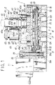
- Fig. 1 is a cross-sectional view showing a tube coupling according to this invention attached to a solenoid pilot change-over valve.
- Fig. 2 is a perspective view similar to Fig. 1.
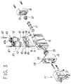
- Fig. 3 is an exploded perspective view similar to Fig. 1.
- Fig. 4 is an exploded perspective view of a tube coupling and a metal holder thereof.
- reference numeral 1 designates a solenoid pilot change-over valve that is an example of a fluidic apparatus, and 2 a tube coupling attached to the change-over valve 1.
- the change-over valve 1 comprises a main valve segment 10 that regulates the flow of compressed air or other main fluid and an electromagnetically actuated pilot valve 11 that regulates the flow of a pilot fluid that switches the main valve segment 10.
- the main valve segment 10 has a substantially rectangular parallelpiped valve body 15.
- the valve body 15 has a round intake port P and exhaust ports EA and EB opening in the bottom surface thereof, rectangular output ports A and B opening in the flat top surface thereof, and a valve bore 16 that communicates with the individual ports, with an axially slidable spool-type valve body 17 inserted in the valve bore 16. Rectangular end plates 18 and 19 are attached to both ends of the valve body 15.
- end plates 18 and 19 are formed a smaller-diameter piston chamber 20 and a larger-diameter piston chamber 21, with a smaller-diameter piston 22 and a larger-diameter piston 23 having pressure-receiving faces of different sizes fitted therein so as to be slidable in the axial direction of the main valve body 17.
- the smaller-diameter piston chamber 20 always communicates with the intake port P by means of a pilot fluid passage 25, whereas the larger-diameter piston chamber 21 communicates with the intake port P by means of pilot fluid passages 26a, 26b, 26c and 26d through a hand-actuating mechanism 28 and the pilot valve 11.
- the pilot fluid supplied to or discharged from the larger-diameter piston chamber through the intake port P by the motion of the pilot valve 11 moves the main valve body 17 back and forth.
- the ports P and A and the ports B and EB communicate with each other.
- the ports P and B and the ports A and EA communicate with each other.
- pilot fluid passages 26a and 26b communicate directly with each other to connect the larger-diameter piston chamber 21 to the intake port P.
- a detachable tube coupling 2 mounted on the top surface of the change-over valve 1 connects a tube 40, such as flexible hoses of synthetic resin or rubber, to the output ports A and B provided in the same surface.
- the tube coupling 2 comprises a base 41 fastened to the change-over valve 1, a metal holder 42 to attach a tube connector 43 to the base 41, and the tube connector 43 for connecting the tube 40.
- connection ports 45 whose number is the same as that of the output ports A and B and multiple bolt holes 46 to pass bolts 47 therethrough.
- An annular sealer 48 to surround each connection port 45 is attached to the flat bottom surface of the base 41.
- the metal holder 42 is S-shaped when viewed from above, with two U-shaped notches 51 cut from opposite sides of a thin metal sheet having a contour analogous to that of the base 41.
- the tube connector 43 is laterally slid from an opening 51a into the notch 51, the edge of the notch 51 interlocks with a groove 61 cut around the tube connector 43.
- the metal holder 42 is fastened to the top surface of the base 41, therefore, the metal holder 42 holds each tube connector 43 on the base 41, with the joint 43a at the lower end thereof fitted in the connector hole 45a
- the metal holder 42 is fastened to the base 41 by screwing the bolts 47 into the bolt holes 52 provided at both ends of the base 41.
- the tube connector 43 can be easily removed from the base 41 and metal holder 42 by laterally sliding out of the notch 51 after unfastening the bolts 47 and detaching the metal holder 42 from the base 41.
- Two projections 54 formed around the connection ports 45 in the top surface of the base 41 have an arched inner surface and are provided at intervals so as to mate with the openings 51a of the notches 51 in the metal holder 42.
- the projections 54 are adapted to come in contact with the side of the tube connectors 43 fastened to the base 41.
- the projections securely fasten the tube connectors 43 to the base 41 even when the metal holder 42 does not engage with the tube connectors 43 at the openings 51a.
- the number of the projections 54 is not limited to two, but may be either one or three or even more.
- the tube connector 43 connects the tube 40 by simply inserting the end thereof into a connection port 43b provided therein.
- the tube connector 43 has the joint 43a, an outer cylinder 60 of synthetic resin having the engaging groove 61 mentioned before, an elastic metal chuck 62 adapted to engage with the outer surface of the tube 40 to keep the tube in position, and a release member 63 of synthetic resin that disengages the chuck 62 from the tube 40 to permit the removal thereof.
- a cylindrical guide 64 of synthetic resin keeps the cylindrical chuck 62 in position.
- the lower end of the chuck 62 is slit into expandable side walls 62a, whereas the heavier-walled upper end thereof remains unslit.
- the tips of the lower bent ends 62b of the side walls 62a form an edge 66 that bites into the tube 40.
- An elastic collet 67 presses the side walls 62a of the chuck 62 inward.
- a sealer 68 coming in contact with the periphery of the tube 40 is provided below the collet 67.
- the cylindrical release member 63 has a pressing segment 63a that comes in contact with the bent ends 62b of the chuck 62.
- the pressing segment 63a comes in contact with the bent ends 62b.
- the bent ends 62b thus expanded outward disengage the edge 66 from the tube 40.
- the edge 66 at the lower end of the chuck 62 bites into the periphery of the tube 40 to accomplish the connection thereof.
- the tube 40 is disconnected from the tube connector 43 by pressing in the release member 63, whereupon the pressing segment 63a at the lower end of the release member 63 expands outward the bent ends 62b of the side walls 62a to disengage the edge 66 from the tube 40.
- the tube 40 thus freed can be drawn out.
- the tube coupling 2 assures easy and secure connection of the tube 40 to ports of any shape and size, whether rectangular as shown in the figures or circular or of such size as does not match the joint 43a of the tube connector 43.
- the tube 40 can be securely connected to ports of different sizes and shapes by the use of the tube coupling 2 of this invention.
- the shape and effective opening area of the connection port 45 should preferably be such as are suited for use with the change-over valve whose ports have the largest diameter and area of the group considered.
- the tube connector 43 can be easily and quickly removed from the base 41 for replacement with a new one by unfastening the bolts 47, detaching the metal holder 42 from the base 41, and laterally sliding the tube connector 43 out of the notches 51.
Landscapes
- Engineering & Computer Science (AREA)
- General Engineering & Computer Science (AREA)
- Mechanical Engineering (AREA)
- Physics & Mathematics (AREA)
- Fluid Mechanics (AREA)
- Quick-Acting Or Multi-Walled Pipe Joints (AREA)
Priority Applications (3)
| Application Number | Priority Date | Filing Date | Title |
|---|---|---|---|
| DE1993620823 DE69320823T2 (de) | 1993-12-07 | 1993-12-07 | Rohrverbindung für Fluidapparate |
| EP93309830A EP0657678B1 (fr) | 1993-12-07 | 1993-12-07 | Raccord de tuyaux pour appareil à fluide |
| US08/162,780 US5415437A (en) | 1993-12-07 | 1993-12-08 | Tube coupling for fluidic apparatus |
Applications Claiming Priority (2)
| Application Number | Priority Date | Filing Date | Title |
|---|---|---|---|
| EP93309830A EP0657678B1 (fr) | 1993-12-07 | 1993-12-07 | Raccord de tuyaux pour appareil à fluide |
| US08/162,780 US5415437A (en) | 1993-12-07 | 1993-12-08 | Tube coupling for fluidic apparatus |
Publications (2)
| Publication Number | Publication Date |
|---|---|
| EP0657678A1 true EP0657678A1 (fr) | 1995-06-14 |
| EP0657678B1 EP0657678B1 (fr) | 1998-09-02 |
Family
ID=26134591
Family Applications (1)
| Application Number | Title | Priority Date | Filing Date |
|---|---|---|---|
| EP93309830A Expired - Lifetime EP0657678B1 (fr) | 1993-12-07 | 1993-12-07 | Raccord de tuyaux pour appareil à fluide |
Country Status (2)
| Country | Link |
|---|---|
| US (1) | US5415437A (fr) |
| EP (1) | EP0657678B1 (fr) |
Families Citing this family (7)
| Publication number | Priority date | Publication date | Assignee | Title |
|---|---|---|---|---|
| JP3655367B2 (ja) * | 1994-09-30 | 2005-06-02 | Smc株式会社 | リニアアクチュエータ |
| FR2764948B1 (fr) * | 1997-06-19 | 1999-08-20 | Hispano Suiza Sa | Bloc hydraulique muni d'un systeme de montage de securite de branchement |
| ATE313710T1 (de) | 1999-08-27 | 2006-01-15 | Delphi Tech Inc | Verbindungsanordnung |
| JP4284687B2 (ja) * | 2005-04-26 | 2009-06-24 | Smc株式会社 | 真空及び真空破壊用複合弁 |
| JP4554482B2 (ja) * | 2005-09-26 | 2010-09-29 | 株式会社コガネイ | マニホールド電磁弁 |
| JP2013060989A (ja) * | 2011-09-12 | 2013-04-04 | Yazaki Energy System Corp | 高圧ホースと圧力調整器のホース継手の接続構造、及び、圧力調整器 |
| CN110778818A (zh) | 2014-10-09 | 2020-02-11 | 可得制品公司 | 具有固位夹子构件的联接组件 |
Citations (3)
| Publication number | Priority date | Publication date | Assignee | Title |
|---|---|---|---|---|
| DE2431680A1 (de) * | 1973-07-03 | 1975-01-30 | Legris France Sa | Verteiler in elementbauweise fuer flude |
| EP0168333A1 (fr) * | 1984-06-14 | 1986-01-15 | S.A. DES ETABLISSEMENTS STAUBLI (France) | Dispositif de raccord pour le branchement simultané d'une série de circuits |
| EP0521776A1 (fr) * | 1991-07-05 | 1993-01-07 | Automobiles Peugeot | Dispositif de raccordement de deux tuyaux à deux conduits, en particulier pour véhicule automobile |
Family Cites Families (14)
| Publication number | Priority date | Publication date | Assignee | Title |
|---|---|---|---|---|
| GB140352A (en) * | 1919-11-28 | 1920-03-25 | Thomas Sugden | Improvements relating to superheaters |
| FR576232A (fr) * | 1924-01-23 | 1924-08-13 | Ets Delaunay Belleville Sa | Dispositif de fixation des tubes démontables à des parois de réservoirs |
| GB772158A (en) * | 1955-04-04 | 1957-04-10 | Gaskell & Chambers Ltd | Means for coupling a pipe or pipes to a barrel or other liquid container |
| US3142358A (en) * | 1962-08-20 | 1964-07-28 | Champ Items Inc | Kit for auxiliary lubrication system for an engine |
| US3869153A (en) * | 1974-07-22 | 1975-03-04 | Gen Motors Corp | Double tube mounting assembly |
| US3929356A (en) * | 1974-11-13 | 1975-12-30 | Gen Motors Corp | Tube to block mounting assembly |
| US4116476A (en) * | 1977-11-11 | 1978-09-26 | Porter Gary K | Quick disconnect coupler assembly |
| US4468054A (en) * | 1982-11-03 | 1984-08-28 | The Singer Company | Flange mounted thermostatic expansion valve |
| FR2603361B1 (fr) * | 1986-09-01 | 1989-05-19 | Staubli Sa Ets | Raccord double pour la jonction amovible de canalisations jumelees |
| US4893845A (en) * | 1988-04-18 | 1990-01-16 | Proprietary Technology, Inc. | Firewall heater line adapter |
| DE3825313A1 (de) * | 1988-07-26 | 1990-02-01 | Linde Ag | Vorrichtung fuer die befestigung von druckschlaeuchen in anschlussbohrungen |
| JPH0271067A (ja) * | 1988-09-05 | 1990-03-09 | Showa Alum Corp | 受液器 |
| US5169178A (en) * | 1990-06-14 | 1992-12-08 | Modine Manufacturing Co. | Fitting for use in a heat exchange system |
| US5271646A (en) * | 1992-05-04 | 1993-12-21 | Aeroquip Corporation | Coupling assembly |
-
1993
- 1993-12-07 EP EP93309830A patent/EP0657678B1/fr not_active Expired - Lifetime
- 1993-12-08 US US08/162,780 patent/US5415437A/en not_active Expired - Lifetime
Patent Citations (3)
| Publication number | Priority date | Publication date | Assignee | Title |
|---|---|---|---|---|
| DE2431680A1 (de) * | 1973-07-03 | 1975-01-30 | Legris France Sa | Verteiler in elementbauweise fuer flude |
| EP0168333A1 (fr) * | 1984-06-14 | 1986-01-15 | S.A. DES ETABLISSEMENTS STAUBLI (France) | Dispositif de raccord pour le branchement simultané d'une série de circuits |
| EP0521776A1 (fr) * | 1991-07-05 | 1993-01-07 | Automobiles Peugeot | Dispositif de raccordement de deux tuyaux à deux conduits, en particulier pour véhicule automobile |
Also Published As
| Publication number | Publication date |
|---|---|
| US5415437A (en) | 1995-05-16 |
| EP0657678B1 (fr) | 1998-09-02 |
Similar Documents
| Publication | Publication Date | Title |
|---|---|---|
| US4978148A (en) | Coupling for multi-passage tube | |
| US4294473A (en) | Device at mutually lockable first and second parts | |
| US4754782A (en) | Hose assembly & clip therefor | |
| EP0758069B1 (fr) | Elément-support de serrage pour raccord de tuyaux d'une vanne de commutation | |
| EP0100326B1 (fr) | Raccord pour fluides et son procede de fabrication | |
| EP0268251B1 (fr) | Raccord de tuyau pour utilisation avec un assemblage de tubes à parois multiples | |
| US4600221A (en) | Connection system for flexible tubing | |
| CA2345975C (fr) | Ensemble connecteur push-pull et ressort pneumatique | |
| AU686687B2 (en) | Valve stack assembly | |
| US5415437A (en) | Tube coupling for fluidic apparatus | |
| KR100286704B1 (ko) | 전자밸브 조립체 | |
| US20030038479A1 (en) | Device for linking fluid-conditioning units | |
| EP0592559B1 (fr) | Dispositif de branchement et de regulation pour des machines hydrauliques | |
| US20060278272A1 (en) | Expandable gas or fluid distribution system | |
| US4846505A (en) | Connecting piece | |
| US7389798B2 (en) | Plug for a port | |
| US4709945A (en) | Prismatic connection member for the supply of valves or the like | |
| US7353842B2 (en) | Air fitting with an integral check valve | |
| WO2006105059A1 (fr) | Manometre pour systeme de distribution de gaz ou de fluides expansibles | |
| KR970005329Y1 (ko) | 유체압 기기에 대한 배관용 접속장치 | |
| EP1070854A3 (fr) | Distributeur | |
| JPH0113909Y2 (fr) | ||
| JPH0113910Y2 (fr) | ||
| JPH0113914Y2 (fr) | ||
| JPH0113913Y2 (fr) |
Legal Events
| Date | Code | Title | Description |
|---|---|---|---|
| PUAI | Public reference made under article 153(3) epc to a published international application that has entered the european phase |
Free format text: ORIGINAL CODE: 0009012 |
|
| 17P | Request for examination filed |
Effective date: 19931215 |
|
| AK | Designated contracting states |
Kind code of ref document: A1 Designated state(s): DE FR GB IT |
|
| 17Q | First examination report despatched |
Effective date: 19961107 |
|
| GRAG | Despatch of communication of intention to grant |
Free format text: ORIGINAL CODE: EPIDOS AGRA |
|
| GRAG | Despatch of communication of intention to grant |
Free format text: ORIGINAL CODE: EPIDOS AGRA |
|
| GRAH | Despatch of communication of intention to grant a patent |
Free format text: ORIGINAL CODE: EPIDOS IGRA |
|
| GRAH | Despatch of communication of intention to grant a patent |
Free format text: ORIGINAL CODE: EPIDOS IGRA |
|
| GRAA | (expected) grant |
Free format text: ORIGINAL CODE: 0009210 |
|
| AK | Designated contracting states |
Kind code of ref document: B1 Designated state(s): DE FR GB IT |
|
| REF | Corresponds to: |
Ref document number: 69320823 Country of ref document: DE Date of ref document: 19981008 |
|
| ET | Fr: translation filed | ||
| PLBE | No opposition filed within time limit |
Free format text: ORIGINAL CODE: 0009261 |
|
| STAA | Information on the status of an ep patent application or granted ep patent |
Free format text: STATUS: NO OPPOSITION FILED WITHIN TIME LIMIT |
|
| 26N | No opposition filed | ||
| PGFP | Annual fee paid to national office [announced via postgrant information from national office to epo] |
Ref country code: GB Payment date: 20011205 Year of fee payment: 9 |
|
| PGFP | Annual fee paid to national office [announced via postgrant information from national office to epo] |
Ref country code: FR Payment date: 20011212 Year of fee payment: 9 |
|
| REG | Reference to a national code |
Ref country code: GB Ref legal event code: IF02 |
|
| PG25 | Lapsed in a contracting state [announced via postgrant information from national office to epo] |
Ref country code: GB Free format text: LAPSE BECAUSE OF NON-PAYMENT OF DUE FEES Effective date: 20021207 |
|
| GBPC | Gb: european patent ceased through non-payment of renewal fee | ||
| PG25 | Lapsed in a contracting state [announced via postgrant information from national office to epo] |
Ref country code: FR Free format text: LAPSE BECAUSE OF NON-PAYMENT OF DUE FEES Effective date: 20030901 |
|
| REG | Reference to a national code |
Ref country code: FR Ref legal event code: ST |
|
| PG25 | Lapsed in a contracting state [announced via postgrant information from national office to epo] |
Ref country code: IT Free format text: LAPSE BECAUSE OF NON-PAYMENT OF DUE FEES;WARNING: LAPSES OF ITALIAN PATENTS WITH EFFECTIVE DATE BEFORE 2007 MAY HAVE OCCURRED AT ANY TIME BEFORE 2007. THE CORRECT EFFECTIVE DATE MAY BE DIFFERENT FROM THE ONE RECORDED. Effective date: 20051207 |
|
| PGFP | Annual fee paid to national office [announced via postgrant information from national office to epo] |
Ref country code: DE Payment date: 20121220 Year of fee payment: 20 |
|
| REG | Reference to a national code |
Ref country code: DE Ref legal event code: R071 Ref document number: 69320823 Country of ref document: DE |
|
| REG | Reference to a national code |
Ref country code: DE Ref legal event code: R071 Ref document number: 69320823 Country of ref document: DE |
|
| PG25 | Lapsed in a contracting state [announced via postgrant information from national office to epo] |
Ref country code: DE Free format text: LAPSE BECAUSE OF EXPIRATION OF PROTECTION Effective date: 20131210 |