EP0657688A2 - Vorrichtung und Verfahren zur Verbrennung - Google Patents
Vorrichtung und Verfahren zur Verbrennung Download PDFInfo
- Publication number
- EP0657688A2 EP0657688A2 EP94119176A EP94119176A EP0657688A2 EP 0657688 A2 EP0657688 A2 EP 0657688A2 EP 94119176 A EP94119176 A EP 94119176A EP 94119176 A EP94119176 A EP 94119176A EP 0657688 A2 EP0657688 A2 EP 0657688A2
- Authority
- EP
- European Patent Office
- Prior art keywords
- fluid fuel
- chamber
- fluid
- dispersing
- atomizing
- Prior art date
- Legal status (The legal status is an assumption and is not a legal conclusion. Google has not performed a legal analysis and makes no representation as to the accuracy of the status listed.)
- Granted
Links
Images

Classifications
-
- F—MECHANICAL ENGINEERING; LIGHTING; HEATING; WEAPONS; BLASTING
- F23—COMBUSTION APPARATUS; COMBUSTION PROCESSES
- F23C—METHODS OR APPARATUS FOR COMBUSTION USING FLUID FUEL OR SOLID FUEL SUSPENDED IN A CARRIER GAS OR AIR
- F23C6/00—Combustion apparatus characterised by the combination of two or more combustion chambers or combustion zones, e.g. for staged combustion
- F23C6/04—Combustion apparatus characterised by the combination of two or more combustion chambers or combustion zones, e.g. for staged combustion in series connection
- F23C6/045—Combustion apparatus characterised by the combination of two or more combustion chambers or combustion zones, e.g. for staged combustion in series connection with staged combustion in a single enclosure
-
- F—MECHANICAL ENGINEERING; LIGHTING; HEATING; WEAPONS; BLASTING
- F23—COMBUSTION APPARATUS; COMBUSTION PROCESSES
- F23D—BURNERS
- F23D11/00—Burners using a direct spraying action of liquid droplets or vaporised liquid into the combustion space
- F23D11/10—Burners using a direct spraying action of liquid droplets or vaporised liquid into the combustion space the spraying being induced by a gaseous medium, e.g. water vapour
- F23D11/106—Burners using a direct spraying action of liquid droplets or vaporised liquid into the combustion space the spraying being induced by a gaseous medium, e.g. water vapour medium and fuel meeting at the burner outlet
- F23D11/107—Burners using a direct spraying action of liquid droplets or vaporised liquid into the combustion space the spraying being induced by a gaseous medium, e.g. water vapour medium and fuel meeting at the burner outlet at least one of both being subjected to a swirling motion
-
- F—MECHANICAL ENGINEERING; LIGHTING; HEATING; WEAPONS; BLASTING
- F23—COMBUSTION APPARATUS; COMBUSTION PROCESSES
- F23D—BURNERS
- F23D11/00—Burners using a direct spraying action of liquid droplets or vaporised liquid into the combustion space
- F23D11/36—Details
-
- F—MECHANICAL ENGINEERING; LIGHTING; HEATING; WEAPONS; BLASTING
- F23—COMBUSTION APPARATUS; COMBUSTION PROCESSES
- F23C—METHODS OR APPARATUS FOR COMBUSTION USING FLUID FUEL OR SOLID FUEL SUSPENDED IN A CARRIER GAS OR AIR
- F23C2201/00—Staged combustion
- F23C2201/20—Burner staging
-
- F—MECHANICAL ENGINEERING; LIGHTING; HEATING; WEAPONS; BLASTING
- F23—COMBUSTION APPARATUS; COMBUSTION PROCESSES
- F23D—BURNERS
- F23D2214/00—Cooling
-
- F—MECHANICAL ENGINEERING; LIGHTING; HEATING; WEAPONS; BLASTING
- F23—COMBUSTION APPARATUS; COMBUSTION PROCESSES
- F23G—CREMATION FURNACES; CONSUMING WASTE PRODUCTS BY COMBUSTION
- F23G2900/00—Special features of, or arrangements for incinerators
- F23G2900/54402—Injecting fluid waste into incinerator
Definitions
- the present invention relates to an apparatus useful for combusting fluid fuel, e.g, liquid fuel, and the process for carrying out the same.
- fluid fuel e.g, liquid fuel
- burners have been used in industrial furnaces to melt glass forming ingredients or metals, to incinerate waste or to combust chemical reactants.
- these burners comprise a passageway for ejecting fuel and a passageway for emitting oxidant, as shown by, for example; U.S. Patent No. 5,104,310 and Brazilian Patent No. 8,503,088.
- the fuel is normally atomized with pressurized air, pressurized steam or mechanical fuel atomizing means and combusted with a substantial amount of oxidant.
- the oxidant employed is either an oxygen enriched air or technically pure oxygen rather than air, the combustion efficiency may be enhanced.
- oxygen enriched air or pure oxygen contains less inert nitrogen than does air for an equivalent amount of oxygen.
- the pure oxygen or oxygen enriched air is known to increase the combustion temperature.
- failure to control the combustion temperature and flame length resulting from using the pure oxygen or oxygen enriched air can damage the burners and/or their associated furnaces.
- an unsafe condition may be created if fuel, such as oil, is allowed to flow into a passageway which is used for emitting oxidant.
- the oil in the oxygen pipe for example, can lead to an explosion since it can be ignited in the presence of oxygen. Therefore, there is a genuine need for apparatus and processes, which are useful for mitigating or alleviating such problems.
- One aspect of the present invention relates to a process for controlling the combustion temperature and flame length produced by a burner through combusting fluid fuel in at least two combustion zones.
- This combustion process comprises:
- Another aspect of the present invention relates to a burner capable of burning fluid fuel, more particularly liquid fuel, in at least two combustion zones.
- the design of the burner is such that it is capable of minimizing the risk associated with the flow of fluid fuel, such as oil, into oxygen emitting passageways and is capable of maintaining a desired flame length.
- the burner comprises:
- At least one first outlet port comprises a plurality of bores at an angle with respect to the central axis of the elongated body.
- the first annular passageway furnished between the interior wall surface of the first housing means and the outer wall surface of the elongated body can be used to eject fluid fuel into the chamber.
- the first annular passageway may be terminated with at least one second outlet port defined by at least one groove on the outer wall surface of said elongated body. At least one groove may be a plurality of spiralling grooves on the outer surface of the elongated body to provide swirling fluid fuel into the chamber.
- the chamber formed by the first housing means and the second annular passageway formed by the second housing means may be expanded obliquely toward their discharge end openings in the form of a trumpet-end or a cone to prevent fluid fuel, such as oil, from accumulating inside of the chamber and/or the second annular passageway.
- fluid fuel such as oil
- a substantially homogeneous mixture or “homogeneous mixture” means a thoroughly, uniformly or well mixed mixture containing fluid fuel and a fluid fuel atomizing or dispersing fluid containing oxygen.
- a plurality of bores or "a plurality of grooves” means two or more bores or grooves.
- At least one outlet port means one or more outlet ports, bores or grooves.
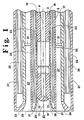
- Figure 1 is a schematic cross-sectional view of the frontal section of a burner according to one embodiment of the invention.
- Figure 2 is a front view of the burner shown in Figure 1.
- Figure 3 is a cross-sectional view of spiralling grooves on the outer surface of an elongated body (nozzle assembly), which is another embodiment of the invention.
- One aspect of the present invention lies in combusting fluid fuel in at least two combustion zones wherein the fluid fuel is partially combusted with a fluid fuel atomizing or dispersing fluid containing oxygen, e.g., high velocity oxygen enriched air or pure oxygen, in an initial combustion zone and then is combusted with at least a stoichiometric amount of oxidant in at least one subsequent combustion zone.
- a fluid fuel atomizing or dispersing fluid containing oxygen e.g., high velocity oxygen or oxygen enriched air
- the fluid fuel atomizing or dispersing fluid containing oxygen e.g., high velocity oxygen or oxygen enriched air
- the atomization or dispersement of the fluid fuel caused by the fluid fuel atomizing or dispersing fluid containing oxygen is such that a substantially homogenous mixture, e.g., a thoroughly mixed mixture or a well mixed mixture containing both the fluid fuel and the fluid fuel atomizing fluid containing oxygen, is formed.
- the formation of the substantially homogeneous mixture causes the fluid fuel in the mixture to be partially combusted with the fluid fuel atomizing or dispersing fluid containing oxygen.
- This partial combustion of the fluid fuel is carried out in a chamber available within the burner, without a substantial amount of oxygen.
- the volumetric rate of the fluid fuel atomizing or dispersing fluid containing oxygen employed may be adjusted or regulated to obtain the desired combustion temperature and the desired flame length. The adjustment, for example, can be made based on the transmitted and/or monitored temperature or flame conditions.
- the partially combusted fluid fuel is further combusted with at least a stoichiometric amount of oxidant in at least one subsequent combustion zone.
- the subsequent combustion zone is located outside of the burner to minimize damage to the burner due to the high temperature resulting from the subsequent combustion.
- the advantages of this combustion process lie in, among other things, utilizing the energy generated by the fluid fuel atomizing or dispersing fluid, enhancing dispersement and combustion of the fluid fuel and reducing the combustion temperature involved. These advantages are attained along with the reduced NO x formation, the desired flame pattern and length and the improved life of the burner.
- burners which are capable of carrying out the above combustion process.
- the burners may have additional features which are useful for reducing or preventing the flow of fluid fuel, such as oil or other liquid fuel, into the outlet for ejecting the fluid fuel atomizing or dispersing fluid containing oxygen and the outlet for ejecting oxidant.
- the burner comprises, among other things, an elongated body (3), a first housing means (5) and a second housing means (7).
- the elongated body (3) and housing means (5 and 7) may be cylindrical and may be made with various high temperature, chemical and corrosion resistant materials, such as nickel and high nickel alloys sold under the trademark "MONEL®", "INCONEL®” or "INCOLY®”.
- These high nickel alloys generally contain about 30 to 80 % nickel by weight, about 0 to 50 % iron by weight, about 0 to 50 % chromium by weight and optionally about 0.5 to 35 % by weight of other metals, such as titanium, copper, aluminum, cobalt and/or molybdenum.
- the percentage of iron or chromium is preferably varied from about 1 to 48 % by weight.
- the elongated body (3), a nozzle assembly, has at least one inner passageway (9) terminating with at least one first outlet port (13).
- the first outlet port (13) has a cross-sectional area smaller than the cross-sectional area of the inner passageway.
- the first outlet port (13) may be defined by a plurality of bores which are directed at an angle with respect to the central axis (c) of the elongated body (3).
- the first outlet port (13) may also be radially spaced from the central axis (c) of the elongated body (3).
- the first housing means (5) surrounds and extends beyond the length of the elongated body (3) to form a combustion chamber (17) and a first annular passageway (19).
- the combustion chamber (17) is located in front of or downstream of the first outlet port (13) while the first annular passageway (19) is located between the interior wall surface of the first housing means (5) and the outer wall surface of the elongated body (3).
- the first annular passageway (19) may be terminated with at least one second outlet port (20).
- the second outlet port (20) may be defined by a plurality of spiralling grooves which are formed on the outer surface of the elongated body (3), as shown by Figure 2.
- the second outlet port (20) having a cross-sectional area or diameter smaller than the cross-sectional area or diameter of the annular passageway (19) is in fluid communication with the combustion chamber (17).
- the combustion chamber (17) may be defined by having an internal wall surface in the form of a cone or a trumpet end.
- the discharge end section of the first housing means (5) is flared outwardly away from the longitudinal axis of the first housing means, e.g., at an angle ranging from about 10° to about 30°.
- a cooling jacket (21) may be provided on the outer surface of the first housing means (5).
- the cooling jacket (21) comprises at least one first compartment (23) for receiving coolant from a source outside of the cooling jacket (21) and at least one second compartment (25) for receiving and discharging the coolant from the first compartment (23).
- the cooling jacket (21) covers at least a portion of the first housing means, e.g., at least a portion of the first housing means forming the combustion chamber (17).
- the jacket or compartments may be made with stainless steel or high nickel alloys to prevent corrosion within the jacket or compartments.
- the second housing means (7) which may be coupled to the cooling jacket (21) or the first housing means (5) by at least one spacer or other coupling means (31), surrounds the cooling jacket (21) or the first housing means (5) to form a second annular passageway (27) therebetween.
- the discharge end section of the second housing means (7) has an internal wall surface in the form of a cone or a trumpet end. Such an internal wall surface may be obtained by flaring the discharge end section of the second housing means (7) outwardly away from the longitudinal axis of the second housing means (7).
- the discharge end section of the second housing means (7) at least partially should cover or surround the combustion chamber (17) so that any liquid or oil dripping from the combustion chamber (17) is prevented from entering the second annular passageway (27).
- a cooling jacket (33) may be provided on the outer surface of the second housing means (7).
- the cooling jacket (33) comprises at least one first compartment (35) for receiving coolant from a source outside of the cooling jacket (33) and at least one second compartment (37) for receiving and discharging the coolant from the first compartment (35).
- the cooling jacket (33) covers at least a portion of the second housing means in the vicinity of the discharge end opening (29), e.g., a portion of the second housing means covering the combustion chamber (17) which is formed by the first housing means (5).
- the jacket or compartments may be made with stainless steel or high nickel alloys to prevent corrosion within the jacket or compartments.
- fluid fuel such as oil, other liquid fuel or liquid waste having a heating value of about at least 3000 K cal/Kg
- fluid fuel is delivered at a pressure of about 2 barg to about 6 barg to the first annular passageway (19) from a fluid fuel source (not shown).
- the fluid fuel delivered to the first annular passageway is ejected from the second outlet port (20).
- the second outlet port (20) may have a cross-sectional area smaller than the first annular passageway (19) to increase the velocity of the fluid fuel ejected therefrom.
- the second outlet port (20) is preferably a plurality of spiralling grooves which are capable of imparting the whirling or swirling effect to the fluid fuel. The spiralling grooves promote dispersement and combustion of the fluid fuel.
- the fluid fuel atomizing or dispersing fluid containing oxygen such as oxygen enriched air or pure oxygen
- a source containing the fluid fuel atomizing or dispersing fluid not shown
- the fluid fuel atomising or dispersing fluid containing oxygen fed to the inner passageway (9) is ejected from the first outlet port (13), such as a plurality of bores.
- the fluid fuel atomizing or dispersing fluid containing oxygen is directed at an angle to the flow direction of the fluid fuel, thus intersecting and dispersing the fluid fuel.
- the first outlet port (13) is inclined at an angle ranging from about 30° to about 60°, preferably from about 40° to about 50°, measured from the central axis (c) of the elongated body (3). Generally, this first outlet port (13) directs the fluid fuel atomizing or dispersing fluid containing oxygen at an angle ranging from about 30° to about 60°, preferably from about 40° to about 50°, measured from the flow direction of the fluid fuel stream ejected from the second outlet port (20).
- the cross-sectional area of the first outlet port (13), such as cylindrical bores, is smaller than the cross-sectional area of the inner passageway (9) to increase the velocity or the volumetric rate of the fluid fuel atomizing or dispersing fluid containing oxygen.
- each cylindrical bore has a diameter ranging from about 1 mm to about 3 mm, preferably about 2 mm to about 2.5 mm.
- This particularly designed first outlet port (13) promotes the formation of a substantially homogeneous mixture containing fluid fuel and fluid fuel atomizing or dispersing fluid containing oxygen, e.g., a well or thoroughly mixed mixture containing fluid fuel and fluid fuel atomizing fluid containing oxygen.
- the fluid fuel can be further atomized or dispersed to form a more homogeneous mixture containing the fluid fuel and fluid fuel atomizing or dispersing fluid containing oxygen, e.g., a more thoroughly mixed mixture containing fluid fuel and fluid fuel atomizing fluid containing oxygen.
- the fluid fuel may be dispersed solely or substantially solely based on the energy generated by the velocity or the volumetric rate of the fluid fuel atomizing or dispersing fluid containing oxygen.
- the volumetric rate at sonic velocity of the fluid fuel atomizing or dispersing fluid is at least about 30 Nm3/hr, preferably at about 50 Nm3/hr to about 70 Nm3/hr.
- the formation of the substantially homogeneous mixture or homogeneous mixture, e.g., a well mixed or a uniformly mixed mixture containing fine oil droplets and oxygen, within the combustion chamber (17) causes partial combustion of the fluid fuel, with the reduced nitrogen oxides formation.
- the partial combustion of fluid fuel engenders a flame which is fixed at the tip of the burner.
- the degree of partial combustion or the temperature resulting from partial combustion can then be regulated or controlled through adjusting the volumetric rate of the fluid fuel atomizing or dispersing fluid containing oxygen.
- the degree of partial combustion is normally regulated to control the combustion temperature of the partial combustion, as well as the combustion temperature of any subsequent combustion so as to minimize or reduce any detrimental effects on the burner.
- the combustion chamber (17) may have a void volume of about 3 cm3 to about 8 cm3, preferably about 6 cm3 to about 7 cm3, in order to accommodate partial combustion of the fluid fuel with the intimately mixed fluid fuel atomizing or dispersing fluid containing oxygen.
- the combustion chamber (17) has an internal wall surface in the form of a cone or a trumpet end. In other words, the combustion chamber (17) is expanding obliquely toward its discharge end opening (18) to prevent liquid fuel, which may be dripping into the chamber (17) from the second outlet port (20) after termination of combustion, from accumulating inside of the chamber (17). By allowing liquid fuel to flow out of the chamber (17), the liquid fuel is prevented from entering the first outlet port, which is used to emit fluid fuel atomizing or dispersing fluid containing oxygen.
- an angle at which the chamber expands promotes the obtention of the desired flame pattern and length inasmuch as the angle, to some extent, affects the distribution, i.e., the flow configuration, of the fluid fuel and fluid fuel atomizing or dispersing fluid containing oxygen.
- the chamber (17) is expanding at an angle ranging from about 10° to about 30°, preferably from about 12° to about 16°, measured from the longitudinal axis of the first housing means.
- the partially combusted fluid fuel leaves the combustion chamber (17) to react with at least a stoichiometric amount of oxidant in at least one subsequent combustion zone, e.g, an area outside of the burner.
- the oxidant such as air, oxygen enriched air or pure oxygen, is fed at a pressure of about 0.5 barg to about 1 barg to the subsequent combustion zone through the annular passageway (27).
- the oxidant leaving the annular passageway (27) envelopes the partially combusted fluid fuel and causes complete combustion of the fluid fuel.
- the end section of the second annular passageway (27) may be expanded obliquely toward its discharge end opening (29) in the form of a trumpet end or a cone.
- the cone or trumpet end shape end section of the second annular passageway (27) is formed by flaring the discharge end section of the second housing means (7) outwardly away from the longitudinal axis of the second housing means at an angle ranging from about 10° to about 30°.
- This discharge end section covers or surrounds at least a portion of the combustion chamber (17) so that any fluid fuel, such as oil, dripping from the combustion chamber (17) is prevented from entering the second annular passageway (27).
- the conical or trumpet end shape end section of the second annular passageway (27) promotes the obtention of the desired flame pattern and length through imparting the desired flow configuration to the oxidant stream.
- a coolant such as water or other cooling fluid
- the heated coolant is replaced continuously by the cooled coolant.
- the fluid fuel By particularly ejecting fluid fuel and fluid fuel atomizing or dispersing fluid containing oxygen, the fluid fuel can be effectively and efficiently dispersed and combusted.
- the energy generated by a fluid fuel atomizing or dispersing fluid containing oxygen is not only used to disperse the fluid fuel but also used to partially combust the fluid fuel.
- This partial combustion in turn allows subsequent complete combustion of the fluid fuel to be occurred at a low temperature range. Since partial and complete combustion of the fluid fuel can be carried out at the low temperature range in the presence of a fluid fuel atomizing fluid containing at least 25% oxygen by volume and an oxidant having an oxygen concentration of at least 25% by volume, the fluid fuel can be combusted with the reduced NO x formation and without substantial damage to the burner.
Landscapes
- Engineering & Computer Science (AREA)
- Chemical & Material Sciences (AREA)
- Combustion & Propulsion (AREA)
- Mechanical Engineering (AREA)
- General Engineering & Computer Science (AREA)
- Nozzles For Spraying Of Liquid Fuel (AREA)
- Spray-Type Burners (AREA)
Applications Claiming Priority (2)
| Application Number | Priority Date | Filing Date | Title |
|---|---|---|---|
| US161519 | 1993-12-06 | ||
| US08/161,519 US5393220A (en) | 1993-12-06 | 1993-12-06 | Combustion apparatus and process |
Publications (3)
| Publication Number | Publication Date |
|---|---|
| EP0657688A2 true EP0657688A2 (de) | 1995-06-14 |
| EP0657688A3 EP0657688A3 (de) | 1996-05-01 |
| EP0657688B1 EP0657688B1 (de) | 1998-03-18 |
Family
ID=22581501
Family Applications (1)
| Application Number | Title | Priority Date | Filing Date |
|---|---|---|---|
| EP94119176A Expired - Lifetime EP0657688B1 (de) | 1993-12-06 | 1994-12-05 | Vorrichtung und Verfahren zur Verbrennung |
Country Status (7)
| Country | Link |
|---|---|
| US (1) | US5393220A (de) |
| EP (1) | EP0657688B1 (de) |
| KR (1) | KR100229964B1 (de) |
| BR (1) | BR9404866A (de) |
| CA (1) | CA2137312A1 (de) |
| DE (1) | DE69409075T2 (de) |
| ES (1) | ES2113602T3 (de) |
Cited By (2)
| Publication number | Priority date | Publication date | Assignee | Title |
|---|---|---|---|---|
| US5975886A (en) * | 1996-11-25 | 1999-11-02 | L'air Liquide, Societe Anonyme Pour L'etude Et L'exploitation Des Procedes Georges Claude | Combustion process and apparatus therefore containing separate injection of fuel and oxidant streams |
| EP0978410A2 (de) | 1998-08-01 | 2000-02-09 | DaimlerChrysler AG | Verfahren zur Steuerung der Antriebseinheit eines Kraftfahrzeuges mit stufenlosem Automatikgetriebe |
Families Citing this family (15)
| Publication number | Priority date | Publication date | Assignee | Title |
|---|---|---|---|---|
| GB2283311B (en) * | 1993-10-07 | 1997-11-05 | Stordy Combustion Eng | Burner and method of burning a fuel |
| AT402963B (de) * | 1995-09-07 | 1997-10-27 | Voest Alpine Ind Anlagen | Verfahren zum verbrennen von brennstoff |
| GB9616442D0 (en) * | 1996-08-05 | 1996-09-25 | Boc Group Plc | Oxygen-fuel burner |
| GB2316161A (en) * | 1996-08-05 | 1998-02-18 | Boc Group Plc | Oxygen-fuel swirl burner |
| GB9709205D0 (en) * | 1997-05-07 | 1997-06-25 | Boc Group Plc | Oxy/oil swirl burner |
| US6174161B1 (en) | 1999-07-30 | 2001-01-16 | Air Products And Chemical, Inc. | Method and apparatus for partial oxidation of black liquor, liquid fuels and slurries |
| FR2827198B1 (fr) | 2001-07-10 | 2004-04-30 | Air Liquide | Dispositif de pulverisation et procede de mise en oeuvre |
| US7117675B2 (en) * | 2002-12-03 | 2006-10-10 | General Electric Company | Cooling of liquid fuel components to eliminate coking |
| US6918255B2 (en) * | 2002-12-03 | 2005-07-19 | General Electric Company | Cooling of liquid fuel components to eliminate coking |
| US7500849B2 (en) * | 2004-01-16 | 2009-03-10 | Air Products And Chemicals, Inc. | Emulsion atomizer nozzle, and burner, and method for oxy-fuel burner applications |
| US20060147853A1 (en) * | 2005-01-06 | 2006-07-06 | Lipp Charles W | Feed nozzle assembly and burner apparatus for gas/liquid reactions |
| US8220271B2 (en) * | 2008-09-30 | 2012-07-17 | Alstom Technology Ltd. | Fuel lance for a gas turbine engine including outer helical grooves |
| US8220269B2 (en) * | 2008-09-30 | 2012-07-17 | Alstom Technology Ltd. | Combustor for a gas turbine engine with effusion cooled baffle |
| US8172566B2 (en) * | 2010-02-18 | 2012-05-08 | Air Products And Chemicals, Inc. | Liquid fuel combustion process and apparatus |
| EP2489939A1 (de) * | 2011-02-18 | 2012-08-22 | Siemens Aktiengesellschaft | Brennkammer mit einem Wandabschnitt und einem Randelement |
Family Cites Families (12)
| Publication number | Priority date | Publication date | Assignee | Title |
|---|---|---|---|---|
| FR1374518A (fr) * | 1963-08-29 | 1964-10-09 | Soc Civ D Rech Etudes Ind | Perfectionnement au chauffage des locaux industriels |
| US3344834A (en) * | 1965-05-26 | 1967-10-03 | United States Steel Corp | Apparatus for partial combustion of hydrocarbon fuels |
| US4065057A (en) * | 1976-07-01 | 1977-12-27 | Durmann George J | Apparatus for spraying heat responsive materials |
| DE3327597A1 (de) * | 1983-07-30 | 1985-02-07 | Deutsche Babcock Werke AG, 4200 Oberhausen | Verfahren und brenner zum verbrennen von fluessigen oder gasfoermigen brennstoffen unter verminderter bildung von nox |
| US5149261A (en) * | 1985-11-15 | 1992-09-22 | Nippon Sanso Kabushiki Kaisha | Oxygen heater and oxygen lance using oxygen heater |
| SE455438B (sv) * | 1986-11-24 | 1988-07-11 | Aga Ab | Sett att senka en brennares flamtemperatur samt brennare med munstycken for oxygen resp brensle |
| US4907961A (en) * | 1988-05-05 | 1990-03-13 | Union Carbide Corporation | Oxygen jet burner and combustion method |
| AT400181B (de) * | 1990-10-15 | 1995-10-25 | Voest Alpine Ind Anlagen | Brenner für die verbrennung von feinkörnigen bis staubförmigen, festen brennstoffen |
| US5188042A (en) * | 1991-04-18 | 1993-02-23 | Praxair Technology, Inc. | Fluid waste burner system |
| US5129335A (en) * | 1991-04-18 | 1992-07-14 | Union Carbide Industrial Gases Technology Corporation | Fluid waste burner system |
| US5129333A (en) * | 1991-06-24 | 1992-07-14 | Aga Ab | Apparatus and method for recycling waste |
| DE4216523C2 (de) * | 1992-05-19 | 1997-01-23 | Webasto Thermosysteme Gmbh | Brenner für ein mit flüssigem Brennstoff betriebenes Heizgerät, insbesondere Fahrzeugzusatzheizgerät |
-
1993
- 1993-12-06 US US08/161,519 patent/US5393220A/en not_active Expired - Fee Related
-
1994
- 1994-12-05 CA CA002137312A patent/CA2137312A1/en not_active Abandoned
- 1994-12-05 ES ES94119176T patent/ES2113602T3/es not_active Expired - Lifetime
- 1994-12-05 KR KR1019940033227A patent/KR100229964B1/ko not_active Expired - Fee Related
- 1994-12-05 EP EP94119176A patent/EP0657688B1/de not_active Expired - Lifetime
- 1994-12-05 DE DE69409075T patent/DE69409075T2/de not_active Expired - Fee Related
- 1994-12-05 BR BR9404866A patent/BR9404866A/pt not_active IP Right Cessation
Cited By (3)
| Publication number | Priority date | Publication date | Assignee | Title |
|---|---|---|---|---|
| US5975886A (en) * | 1996-11-25 | 1999-11-02 | L'air Liquide, Societe Anonyme Pour L'etude Et L'exploitation Des Procedes Georges Claude | Combustion process and apparatus therefore containing separate injection of fuel and oxidant streams |
| US6331107B1 (en) | 1996-11-25 | 2001-12-18 | American Air Liquide, Inc. | Combustion process and apparatus therefore containing separate injection of fuel and oxidant streams |
| EP0978410A2 (de) | 1998-08-01 | 2000-02-09 | DaimlerChrysler AG | Verfahren zur Steuerung der Antriebseinheit eines Kraftfahrzeuges mit stufenlosem Automatikgetriebe |
Also Published As
| Publication number | Publication date |
|---|---|
| DE69409075D1 (de) | 1998-04-23 |
| EP0657688B1 (de) | 1998-03-18 |
| KR100229964B1 (ko) | 1999-11-15 |
| US5393220A (en) | 1995-02-28 |
| ES2113602T3 (es) | 1998-05-01 |
| DE69409075T2 (de) | 1998-09-17 |
| BR9404866A (pt) | 1995-08-01 |
| CA2137312A1 (en) | 1995-06-07 |
| KR950019363A (ko) | 1995-07-22 |
| EP0657688A3 (de) | 1996-05-01 |
Similar Documents
| Publication | Publication Date | Title |
|---|---|---|
| US5393220A (en) | Combustion apparatus and process | |
| US5617997A (en) | Narrow spray angle liquid fuel atomizers for combustion | |
| US5567141A (en) | Oxy-liquid fuel combustion process and apparatus | |
| US5863195A (en) | Oxygen-fuel burner | |
| RU2239139C2 (ru) | Способ получения множества когерентных газовых струй при использовании единственной фурмы (варианты) и фурма для его осуществления | |
| EP0137098A1 (de) | Brenner mit Flammeneinstellbarkeit | |
| US8827176B2 (en) | HVOF torch with fuel surrounding oxidizer | |
| US20150291465A1 (en) | Swirling burner and process for submerged combustion melting | |
| JPH09166308A (ja) | 同軸の燃料および酸化剤出口を有するオキシ−燃料バーナー | |
| WO2000028097A1 (en) | Integrated device to inject technological gases and powdered material and method to use the device for the processing of baths of molten metal | |
| JPH09112814A (ja) | 燃料およびオキシダント流の分離噴射を含む燃焼方法およびその燃焼装置 | |
| JP2015121398A (ja) | 分散燃焼のプロセスおよびバーナ | |
| RU2308645C2 (ru) | Вихревая горелка | |
| US5547368A (en) | Process and device for combustion-enhanced atomization and vaporization of liquid fuels | |
| US6893255B2 (en) | Spray burner for the thermal decomposition of sulphur-containing residues | |
| EP1203188B1 (de) | Industriebrenner für brennstoffe | |
| JPH05141631A (ja) | 囲い内の加熱方法及びバーナ | |
| US20020090587A1 (en) | Burner for high-temperature combustion | |
| US5807530A (en) | Process for burning of sulfur | |
| EP0719180B1 (de) | V-jet atomisateur | |
| JPH0147683B2 (de) | ||
| WO1987002756A1 (fr) | Bruleur a tube radiant | |
| EP0657695B1 (de) | Vorrichtung und Verfahren zur Verbrennung von flüssigen, feste Teilchen enthaltenden Brennstoffen | |
| RU2193141C2 (ru) | Паровая форсунка | |
| WO1997002366A2 (en) | Method and apparatus for after-burning atmospheric gases in a steel smelting arc furnace |
Legal Events
| Date | Code | Title | Description |
|---|---|---|---|
| PUAI | Public reference made under article 153(3) epc to a published international application that has entered the european phase |
Free format text: ORIGINAL CODE: 0009012 |
|
| AK | Designated contracting states |
Kind code of ref document: A2 Designated state(s): BE DE ES FR IT NL |
|
| PUAL | Search report despatched |
Free format text: ORIGINAL CODE: 0009013 |
|
| AK | Designated contracting states |
Kind code of ref document: A3 Designated state(s): BE DE ES FR IT NL |
|
| 17P | Request for examination filed |
Effective date: 19960621 |
|
| 17Q | First examination report despatched |
Effective date: 19961218 |
|
| GRAG | Despatch of communication of intention to grant |
Free format text: ORIGINAL CODE: EPIDOS AGRA |
|
| GRAG | Despatch of communication of intention to grant |
Free format text: ORIGINAL CODE: EPIDOS AGRA |
|
| GRAH | Despatch of communication of intention to grant a patent |
Free format text: ORIGINAL CODE: EPIDOS IGRA |
|
| GRAH | Despatch of communication of intention to grant a patent |
Free format text: ORIGINAL CODE: EPIDOS IGRA |
|
| GRAA | (expected) grant |
Free format text: ORIGINAL CODE: 0009210 |
|
| ITF | It: translation for a ep patent filed | ||
| AK | Designated contracting states |
Kind code of ref document: B1 Designated state(s): BE DE ES FR IT NL |
|
| PG25 | Lapsed in a contracting state [announced via postgrant information from national office to epo] |
Ref country code: NL Free format text: LAPSE BECAUSE OF FAILURE TO SUBMIT A TRANSLATION OF THE DESCRIPTION OR TO PAY THE FEE WITHIN THE PRESCRIBED TIME-LIMIT Effective date: 19980318 Ref country code: BE Free format text: LAPSE BECAUSE OF FAILURE TO SUBMIT A TRANSLATION OF THE DESCRIPTION OR TO PAY THE FEE WITHIN THE PRESCRIBED TIME-LIMIT Effective date: 19980318 |
|
| REF | Corresponds to: |
Ref document number: 69409075 Country of ref document: DE Date of ref document: 19980423 |
|
| REG | Reference to a national code |
Ref country code: ES Ref legal event code: FG2A Ref document number: 2113602 Country of ref document: ES Kind code of ref document: T3 |
|
| ET | Fr: translation filed | ||
| NLV1 | Nl: lapsed or annulled due to failure to fulfill the requirements of art. 29p and 29m of the patents act | ||
| PLBE | No opposition filed within time limit |
Free format text: ORIGINAL CODE: 0009261 |
|
| STAA | Information on the status of an ep patent application or granted ep patent |
Free format text: STATUS: NO OPPOSITION FILED WITHIN TIME LIMIT |
|
| 26N | No opposition filed | ||
| PGFP | Annual fee paid to national office [announced via postgrant information from national office to epo] |
Ref country code: FR Payment date: 19991117 Year of fee payment: 6 |
|
| PGFP | Annual fee paid to national office [announced via postgrant information from national office to epo] |
Ref country code: DE Payment date: 19991118 Year of fee payment: 6 |
|
| PGFP | Annual fee paid to national office [announced via postgrant information from national office to epo] |
Ref country code: ES Payment date: 19991213 Year of fee payment: 6 |
|
| PG25 | Lapsed in a contracting state [announced via postgrant information from national office to epo] |
Ref country code: FR Free format text: LAPSE BECAUSE OF NON-PAYMENT OF DUE FEES Effective date: 20010831 |
|
| REG | Reference to a national code |
Ref country code: FR Ref legal event code: ST |
|
| PG25 | Lapsed in a contracting state [announced via postgrant information from national office to epo] |
Ref country code: DE Free format text: LAPSE BECAUSE OF NON-PAYMENT OF DUE FEES Effective date: 20011002 |
|
| PG25 | Lapsed in a contracting state [announced via postgrant information from national office to epo] |
Ref country code: ES Free format text: LAPSE BECAUSE OF NON-PAYMENT OF DUE FEES Effective date: 20011206 |
|
| REG | Reference to a national code |
Ref country code: ES Ref legal event code: FD2A Effective date: 20020112 |
|
| PG25 | Lapsed in a contracting state [announced via postgrant information from national office to epo] |
Ref country code: IT Free format text: LAPSE BECAUSE OF NON-PAYMENT OF DUE FEES;WARNING: LAPSES OF ITALIAN PATENTS WITH EFFECTIVE DATE BEFORE 2007 MAY HAVE OCCURRED AT ANY TIME BEFORE 2007. THE CORRECT EFFECTIVE DATE MAY BE DIFFERENT FROM THE ONE RECORDED. Effective date: 20051205 |