EP0657704A1 - Chauffe eau - Google Patents
Chauffe eau Download PDFInfo
- Publication number
- EP0657704A1 EP0657704A1 EP94119552A EP94119552A EP0657704A1 EP 0657704 A1 EP0657704 A1 EP 0657704A1 EP 94119552 A EP94119552 A EP 94119552A EP 94119552 A EP94119552 A EP 94119552A EP 0657704 A1 EP0657704 A1 EP 0657704A1
- Authority
- EP
- European Patent Office
- Prior art keywords
- water
- water heater
- heater according
- pipes
- base body
- Prior art date
- Legal status (The legal status is an assumption and is not a legal conclusion. Google has not performed a legal analysis and makes no representation as to the accuracy of the status listed.)
- Withdrawn
Links
- XLYOFNOQVPJJNP-UHFFFAOYSA-N water Substances O XLYOFNOQVPJJNP-UHFFFAOYSA-N 0.000 title claims abstract description 90
- 238000002485 combustion reaction Methods 0.000 claims abstract description 28
- 239000003344 environmental pollutant Substances 0.000 claims abstract description 24
- 231100000719 pollutant Toxicity 0.000 claims abstract description 24
- 238000009413 insulation Methods 0.000 claims abstract description 17
- 239000003546 flue gas Substances 0.000 claims abstract description 16
- UGFAIRIUMAVXCW-UHFFFAOYSA-N Carbon monoxide Chemical compound [O+]#[C-] UGFAIRIUMAVXCW-UHFFFAOYSA-N 0.000 claims abstract description 15
- 238000002156 mixing Methods 0.000 claims abstract description 6
- 238000005260 corrosion Methods 0.000 claims abstract description 3
- 230000007797 corrosion Effects 0.000 claims abstract description 3
- 239000007789 gas Substances 0.000 claims description 12
- 239000000446 fuel Substances 0.000 claims description 8
- 238000010304 firing Methods 0.000 claims description 5
- 238000010438 heat treatment Methods 0.000 claims description 5
- 239000000463 material Substances 0.000 claims description 5
- 239000003054 catalyst Substances 0.000 claims description 4
- 238000009434 installation Methods 0.000 claims description 2
- 238000007789 sealing Methods 0.000 claims description 2
- 230000001105 regulatory effect Effects 0.000 claims 2
- 230000001276 controlling effect Effects 0.000 claims 1
- 238000004519 manufacturing process Methods 0.000 abstract description 2
- 230000001737 promoting effect Effects 0.000 abstract description 2
- 230000009467 reduction Effects 0.000 abstract description 2
- 230000005540 biological transmission Effects 0.000 abstract 1
- 230000006378 damage Effects 0.000 abstract 1
- 238000003912 environmental pollution Methods 0.000 abstract 1
- 230000007613 environmental effect Effects 0.000 description 6
- 238000013461 design Methods 0.000 description 5
- 238000012546 transfer Methods 0.000 description 5
- 238000005457 optimization Methods 0.000 description 4
- 238000000034 method Methods 0.000 description 3
- 241001156002 Anthonomus pomorum Species 0.000 description 2
- 244000089486 Phragmites australis subsp australis Species 0.000 description 2
- 230000008859 change Effects 0.000 description 2
- 239000000567 combustion gas Substances 0.000 description 2
- 238000001816 cooling Methods 0.000 description 2
- 238000005259 measurement Methods 0.000 description 2
- 238000003825 pressing Methods 0.000 description 2
- 230000008569 process Effects 0.000 description 2
- 229920005830 Polyurethane Foam Polymers 0.000 description 1
- 230000032683 aging Effects 0.000 description 1
- 238000011109 contamination Methods 0.000 description 1
- 238000013016 damping Methods 0.000 description 1
- 238000009826 distribution Methods 0.000 description 1
- 238000005516 engineering process Methods 0.000 description 1
- 238000011156 evaluation Methods 0.000 description 1
- 230000002349 favourable effect Effects 0.000 description 1
- 230000020169 heat generation Effects 0.000 description 1
- 239000011810 insulating material Substances 0.000 description 1
- 230000003993 interaction Effects 0.000 description 1
- 239000002184 metal Substances 0.000 description 1
- 239000000203 mixture Substances 0.000 description 1
- 239000004033 plastic Substances 0.000 description 1
- 229920003023 plastic Polymers 0.000 description 1
- 239000011496 polyurethane foam Substances 0.000 description 1
- 238000012545 processing Methods 0.000 description 1
- 239000000779 smoke Substances 0.000 description 1
- 238000003860 storage Methods 0.000 description 1
- 230000035882 stress Effects 0.000 description 1
- 239000008400 supply water Substances 0.000 description 1
Images



Classifications
-
- F—MECHANICAL ENGINEERING; LIGHTING; HEATING; WEAPONS; BLASTING
- F24—HEATING; RANGES; VENTILATING
- F24H—FLUID HEATERS, e.g. WATER OR AIR HEATERS, HAVING HEAT-GENERATING MEANS, e.g. HEAT PUMPS, IN GENERAL
- F24H1/00—Water heaters, e.g. boilers, continuous-flow heaters or water-storage heaters
- F24H1/0027—Water heaters, e.g. boilers, continuous-flow heaters or water-storage heaters using fluid fuel
- F24H1/0045—Water heaters, e.g. boilers, continuous-flow heaters or water-storage heaters using fluid fuel with catalytic combustion
-
- F—MECHANICAL ENGINEERING; LIGHTING; HEATING; WEAPONS; BLASTING
- F24—HEATING; RANGES; VENTILATING
- F24H—FLUID HEATERS, e.g. WATER OR AIR HEATERS, HAVING HEAT-GENERATING MEANS, e.g. HEAT PUMPS, IN GENERAL
- F24H1/00—Water heaters, e.g. boilers, continuous-flow heaters or water-storage heaters
- F24H1/22—Water heaters other than continuous-flow or water-storage heaters, e.g. water heaters for central heating
- F24H1/24—Water heaters other than continuous-flow or water-storage heaters, e.g. water heaters for central heating with water mantle surrounding the combustion chamber or chambers
- F24H1/26—Water heaters other than continuous-flow or water-storage heaters, e.g. water heaters for central heating with water mantle surrounding the combustion chamber or chambers the water mantle forming an integral body
- F24H1/28—Water heaters other than continuous-flow or water-storage heaters, e.g. water heaters for central heating with water mantle surrounding the combustion chamber or chambers the water mantle forming an integral body including one or more furnace or fire tubes
- F24H1/285—Water heaters other than continuous-flow or water-storage heaters, e.g. water heaters for central heating with water mantle surrounding the combustion chamber or chambers the water mantle forming an integral body including one or more furnace or fire tubes with the fire tubes arranged alongside the combustion chamber
-
- F—MECHANICAL ENGINEERING; LIGHTING; HEATING; WEAPONS; BLASTING
- F24—HEATING; RANGES; VENTILATING
- F24H—FLUID HEATERS, e.g. WATER OR AIR HEATERS, HAVING HEAT-GENERATING MEANS, e.g. HEAT PUMPS, IN GENERAL
- F24H1/00—Water heaters, e.g. boilers, continuous-flow heaters or water-storage heaters
- F24H1/46—Water heaters having plural combustion chambers
-
- F—MECHANICAL ENGINEERING; LIGHTING; HEATING; WEAPONS; BLASTING
- F24—HEATING; RANGES; VENTILATING
- F24H—FLUID HEATERS, e.g. WATER OR AIR HEATERS, HAVING HEAT-GENERATING MEANS, e.g. HEAT PUMPS, IN GENERAL
- F24H9/00—Details
- F24H9/0005—Details for water heaters
- F24H9/001—Guiding means
- F24H9/0015—Guiding means in water channels
-
- F—MECHANICAL ENGINEERING; LIGHTING; HEATING; WEAPONS; BLASTING
- F24—HEATING; RANGES; VENTILATING
- F24H—FLUID HEATERS, e.g. WATER OR AIR HEATERS, HAVING HEAT-GENERATING MEANS, e.g. HEAT PUMPS, IN GENERAL
- F24H9/00—Details
- F24H9/0005—Details for water heaters
- F24H9/001—Guiding means
- F24H9/0026—Guiding means in combustion gas channels
-
- F—MECHANICAL ENGINEERING; LIGHTING; HEATING; WEAPONS; BLASTING
- F24—HEATING; RANGES; VENTILATING
- F24H—FLUID HEATERS, e.g. WATER OR AIR HEATERS, HAVING HEAT-GENERATING MEANS, e.g. HEAT PUMPS, IN GENERAL
- F24H9/00—Details
- F24H9/02—Casings; Cover lids; Ornamental panels
-
- F—MECHANICAL ENGINEERING; LIGHTING; HEATING; WEAPONS; BLASTING
- F24—HEATING; RANGES; VENTILATING
- F24H—FLUID HEATERS, e.g. WATER OR AIR HEATERS, HAVING HEAT-GENERATING MEANS, e.g. HEAT PUMPS, IN GENERAL
- F24H9/00—Details
- F24H9/12—Arrangements for connecting heaters to circulation pipes
- F24H9/13—Arrangements for connecting heaters to circulation pipes for water heaters
Definitions
- the invention relates to a water heater.
- the insulating layer is applied to the outer surface or attached to it or against locally particularly hot parts, such as. B. reset the firebox door.
- the doors are usually pivotable and locked at the front. When locked, a circumferential web presses against the end wall via a seal.
- the door, the hinge and the locking elements are designed to be strong in order to apply the pressure required for the seal.
- Return mixing devices have the task of raising the temperature of the colder return water by adding a portion of the hot supply water to such an extent that a drop below the dew point in the interior of the combustion or exhaust gas side is prevented. It is known to protect the pipes of a water heater from direct contact with the cold return water. With boiler circulation pumps z. B. the return water externally mixed flow water. In other solutions, the pipes are made of multiple layers. These designs are relatively complex. In other solutions, the return water is fed tangentially to the water space. Good mixing is achieved by swirling the water in the water space.
- a relatively large distance must be provided for the swirl between the tube bundle and the outer wall of the water space. This makes the base body relatively large. It is also known to feed the return water radially into the water space and to guide it over a relatively narrow, saddle-shaped sheet arranged around the pipes. The water hits the pipes in the lower part with only a slightly elevated temperature.
- Post-combustion facilities are provided to reduce pollution. You can easily put it in the tube as a wire coil or sheet metal strip be inserted. They give off heat to the subsequent cooler unburned gases and promote their combustion.
- a water heater so that it contains one or two fireboxes and several heating surfaces for flue gas cooling.
- the burner directed into the combustion chamber supplies the combustion chamber with fuel and air and is operated at intervals or / and in a modulating manner to adapt to the power actually required.
- the water heaters are usually designed for continuous operation, so that they work in partial load mode with lower efficiency and / or higher pollutant discharge.
- the object of the invention is to improve the thermal insulation and thereby reduce energy losses and achieve further advantages through the insulation, to provide a lighter door, to facilitate the setting of the pressure on the seal, with simple means an energetically favorable return water mixture and heating to reach and the flue gas pipes against contact with cold return water protect, especially in part-load operation, to increase the efficiency of the water heaters and to reduce the pollutant discharge, to increase the heat transfer area in relation to the volume and to reduce the mass in relation to the heat output, and to specify further means for reducing the environmental impact during heat generation.
- the insulation surrounding the base body of the water heater as a self-supporting shell and, in the preferred embodiment, the fresh air being supplied through the intermediate space formed in this way.
- the insulation is less exposed to high temperatures. It is also possible to use temperature-sensitive, good insulating materials, such as foamed plastics in particular. Due to the lower thermal load, the heat losses are lower with the same insulation properties of the insulation. In principle, the "cooling" of the base body by the fresh air supply does not result in any energy losses, since the fresh air absorbs this heat and leads it back into the combustion chamber.
- the airtight insulation of the base body in connection with an all-round covering up to the chimney and the type of fresh air supply means that any smoke and other gases emitted to the outside from the base body, such as those found in almost every water heater during initial start-up or later Seal aging observed, do not get into the room in which the water heater is located, but are led together with the fresh air into the combustion chamber.
- the door By arranging additional clamping elements for the seal, the door can be made much lighter than before, since the forces required for sealing no longer have to be applied via the lock.
- the load on the tensioning elements acting on the seal is not influenced by the weight of the door, the burner and other attachments.
- the pressure of the seal can be changed without changing the position of the door, burner and lines.
- the cold return water flowing into the gap between the water chamber jacket and the baffle in the upper part of the water space takes part of the hot flow water with the injector and mixes with it in a relatively long way and absorbs further heat from the baffle. It flows towards the firing side and into the lower part of the water space.
- the exit velocity of the preheated return water from the gap between the baffle plate and water chamber jacket in the lower part of the water space is preferably approximately the same over the gap length, it has warmed up sufficiently so that the dew point on the combustion or flue gas side is undershot with a single plate and with relative low-loss flow can be avoided.
- the energy of the airborne sound is broken by the flattened pipe sections which are successively twisted in the direction of the main axis. There is intensive mixing. The heat exchange between the flue gases and the pipe surrounding them and from there to the water in the water space is significantly improved.
- the tube preferably contains internals which reduce its core cross section or exclude rectilinear flow in the rear part. This further improves the heat exchange.
- a tube which can be provided with catalyst material, is preferably installed centrally in the first third of the tube. It promotes post-combustion.
- the catalyst material can be adapted in sections to the temperature and the afterburning can thereby be optimized.
- the pipe according to the invention is cheaper to produce than corrugated pipes.
- the distribution of the fuel flow over many burners creates the possibility of a digital water heater heat output change in such a way that the space surrounding the burners can be adapted in terms of firing technology to an almost constant burner output in all operating states.
- a discreet switching on and off of burners causes a change in the water heater's heating output realized in such a way that the combustion takes place optimally at the combustion points operated in each case, ie with high efficiency and low pollutant discharge.
- the previously known, mostly large-volume central combustion chamber is no longer required and this space is filled with several pipes with a smaller diameter and thus a larger heat transfer area. This leads to an increase in the heat output related to the water heater volume and mass.
- the pollutant contents in the flue gas are measured, fed to a computer and in this a pollutant discharge minimization is carried out according to known optimization processes.
- the constant determination of the emission of pollutants is the basis for the targeted influence with known control engineering means on all parameters influencing the combustion and thus also the pollutant emission.
- the measurement of different pollutants, their multiplicative connection with weighting factors and the use of the result for the water heater control contributes to a reduction in pollutant emissions and creates a relatively low-pollution environment.
- the specific environmental impact actually present at the water heater installation site can be taken into account by optionally entering weighting factors for the individual pollutants.
- optimization can be carried out using means known per se, but also trend phenomena, such as, for example, contamination or wear and, moreover, functional failures can be determined and signaled.
- FIG. 2 shows the design of a burner or flue gas deflection chamber which can be opened like a door and is generally referred to as a door.
- a door 19 is articulated on the end wall 17 by means of a hinge 13. Opposite the hinge 13, the door 19 is fastened to the end wall 17 with a lock (not shown).
- the door 19 On the inside, towards the end wall 17, the door 19 has a web 14 running around between the lock and the hinge 13. It is a short distance from the end wall 17. When the door 19 is locked, the web 14 does not press against the end wall 17. Outside of the web 14 and on the end wall 17 there is a circumferential seal 15.
- clamping elements 18 for example Screws, spring plate
- a clamping sleeve 16 pressed against the end wall 17 and the web 14.
- Insulation 20 for thermal insulation is accommodated within the web 14.
- a burner 4 is fastened in the middle of the door.
- FIG. 1 A second embodiment of the door is shown in FIG.
- the clamping sleeve 16 is fastened to the web 14 and the web 14 itself is designed to be longitudinally elastic with a bellows 21.
- the clamping sleeve 16 is also braced against the end wall 17.
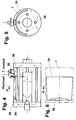
- Figures 4 to 6 show the structure of a device for internal water mixing and heating in the water space 25 of the base body 1 of a water heater.
- the supply and return of the heated or cold water takes place in the rear part of the water space 25.
- a guide plate 24 is arranged above the pipes 30.
- the gap between the baffle 24 and the jacket of the water chamber 25 increases towards the firing side.
- the return water is injected like an injector approximately parallel to the pipes 30 between the guide plate 24 and the jacket of the water space 25. It sucks in relatively warm flow water and mixes with the warm water.
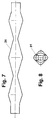
- FIGS. 7 to 9 show the design of a section of a tube 30 with a jacket 31.
- the tube 30, which is initially circular in cross-section, is compressed in sections transverse to the axis with an approximately linear pressing tool to approximately 1/4 of its diameter. Between the pressing processes, the tube is rotated by 90 in each case.
- the cross section of the tube 30 is circular in its front (firing-side) part.
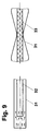
- a further pipe 32 is installed in this part.
- the inflowing gases cool down on the jacket 31.
- the gases flowing through the inner tube 32 cool down much more slowly and can therefore give off heat for a relatively long distance for the afterburning of unburned gases.
- the inner tube 32 can be provided with catalyst material.
- the inner tube 32 extends into the portion of the tube 30 which has already been flattened in sections. In the interplay of the narrowing and widening of the tube 30 with respect to itself and the inner tube 32, acoustic energy is broken and already cooled gases are constantly mixed with still warm gases, thereby ensuring good heat transfer from the gases to the jacket 31 and into the water space 25 (shown in Figure 4).
- Figure 10 shows a section through a water heater.
- the base body 1 is penetrated in the space 27 to be heated by a plurality of pipes 30, each of which is assigned its own fuel supply device 38.
- a bulge 34 promotes combustion
- a turbulator 35 afterburning, surface-enlarging elements 36 heat transfer
- a corrosion-resistant material 37 protects the tube 30.
- a measuring device 39 determines the content of pollutants in the flue gas and passes this value on to the computer 40. Optimization with regard to a minimal pollutant discharge is carried out in the computer with known means and by processing further values, and the number of fuel supply devices 38 to be operated and the speed of the fan 8 are controlled. Devices for closing the air passage openings of the non-operated fuel supply devices 38 are sufficiently known and are therefore not shown here, as are the connections to the water space and others.
- Weighting factors of the individual pollutant measured values can be entered in the computer 40.
- the products of the measured pollutant value and the weighting factor are formed in the computer 40 added.
- the individual and total values are stored in the computer 40 together with further values characterizing the boiler operating state.
Landscapes
- Engineering & Computer Science (AREA)
- Chemical & Material Sciences (AREA)
- Physics & Mathematics (AREA)
- Thermal Sciences (AREA)
- Combustion & Propulsion (AREA)
- Mechanical Engineering (AREA)
- General Engineering & Computer Science (AREA)
- Chemical Kinetics & Catalysis (AREA)
Applications Claiming Priority (12)
| Application Number | Priority Date | Filing Date | Title |
|---|---|---|---|
| DE4342121A DE4342121A1 (de) | 1993-12-10 | 1993-12-10 | Kesseltür |
| DE4342120A DE4342120A1 (de) | 1993-12-10 | 1993-12-10 | Isolierung eines Heizkessels |
| DE4342119A DE4342119C2 (de) | 1993-12-10 | 1993-12-10 | Rauchgasrohr |
| DE4342121 | 1993-12-10 | ||
| DE4342120 | 1993-12-10 | ||
| DE9318956U DE9318956U1 (de) | 1993-12-10 | 1993-12-10 | Einrichtung zur Rücklaufbeimischung in einem Heizkessel |
| DE9318956U | 1993-12-10 | ||
| DE4342119 | 1993-12-10 | ||
| DE9406498U | 1994-04-19 | ||
| DE9406498U DE9406498U1 (de) | 1994-04-19 | 1994-04-19 | Einrichtung zur Minimierung der Schadstoffemission eines Heizkessels |
| DE4414776A DE4414776A1 (de) | 1994-04-19 | 1994-04-19 | Heizkessel |
| DE4414776 | 1994-04-19 |
Publications (1)
| Publication Number | Publication Date |
|---|---|
| EP0657704A1 true EP0657704A1 (fr) | 1995-06-14 |
Family
ID=27544679
Family Applications (1)
| Application Number | Title | Priority Date | Filing Date |
|---|---|---|---|
| EP94119552A Withdrawn EP0657704A1 (fr) | 1993-12-10 | 1994-12-09 | Chauffe eau |
Country Status (1)
| Country | Link |
|---|---|
| EP (1) | EP0657704A1 (fr) |
Cited By (2)
| Publication number | Priority date | Publication date | Assignee | Title |
|---|---|---|---|---|
| EP0757214A1 (fr) * | 1995-08-02 | 1997-02-05 | August Brötje GmbH | Générateur de chaleur pour utilisation à des températures basses et procédé pour la mise en oeuvre du générateur de chaleur |
| DE10350765A1 (de) * | 2003-10-30 | 2005-06-09 | Eisenmann Maschinenbau Gmbh & Co. Kg | Satz von thermischen Nachverbrennungsvorrichtungen |
Citations (9)
| Publication number | Priority date | Publication date | Assignee | Title |
|---|---|---|---|---|
| DE465935C (de) * | 1928-09-27 | Wilhelm Mathiesen | Fluessigkeitserhitzer | |
| GB398494A (en) * | 1932-03-04 | 1933-09-04 | Charles Mensforth Pattison | Improvements in gas or oil burning apparatus for heating and power purposes |
| FR1383810A (fr) * | 1963-09-13 | 1965-01-04 | Rhodiaceta | échangeur thermique tubulaire |
| GB1168116A (en) * | 1966-06-02 | 1969-10-22 | August Broetje | Improvements in Boilers |
| DE3410141A1 (de) * | 1984-03-20 | 1985-10-03 | Buderus Ag, 6330 Wetzlar | Heizungskessel mit rohrfoermigen heizgaskanaelen |
| EP0257867A2 (fr) * | 1986-08-21 | 1988-03-02 | Beaumont(U.K.) Limited | Appareil de chauffage d'eau avec des tubes verticaux |
| AT387450B (de) * | 1986-03-06 | 1989-01-25 | Stelrad Radiatoren & Kessel | Brennerbefeuerter heizungskessel |
| DE3832323A1 (de) * | 1988-09-23 | 1990-03-29 | Omnical Gmbh | Wasserseitiger anschluss eines zentralheizungskessels |
| EP0512220A1 (fr) * | 1991-05-02 | 1992-11-11 | Mayr, Manfred | Chaudière pour chauffage central à brûleur soufflant à huile ou à gaz et pour usage à température basse |
-
1994
- 1994-12-09 EP EP94119552A patent/EP0657704A1/fr not_active Withdrawn
Patent Citations (9)
| Publication number | Priority date | Publication date | Assignee | Title |
|---|---|---|---|---|
| DE465935C (de) * | 1928-09-27 | Wilhelm Mathiesen | Fluessigkeitserhitzer | |
| GB398494A (en) * | 1932-03-04 | 1933-09-04 | Charles Mensforth Pattison | Improvements in gas or oil burning apparatus for heating and power purposes |
| FR1383810A (fr) * | 1963-09-13 | 1965-01-04 | Rhodiaceta | échangeur thermique tubulaire |
| GB1168116A (en) * | 1966-06-02 | 1969-10-22 | August Broetje | Improvements in Boilers |
| DE3410141A1 (de) * | 1984-03-20 | 1985-10-03 | Buderus Ag, 6330 Wetzlar | Heizungskessel mit rohrfoermigen heizgaskanaelen |
| AT387450B (de) * | 1986-03-06 | 1989-01-25 | Stelrad Radiatoren & Kessel | Brennerbefeuerter heizungskessel |
| EP0257867A2 (fr) * | 1986-08-21 | 1988-03-02 | Beaumont(U.K.) Limited | Appareil de chauffage d'eau avec des tubes verticaux |
| DE3832323A1 (de) * | 1988-09-23 | 1990-03-29 | Omnical Gmbh | Wasserseitiger anschluss eines zentralheizungskessels |
| EP0512220A1 (fr) * | 1991-05-02 | 1992-11-11 | Mayr, Manfred | Chaudière pour chauffage central à brûleur soufflant à huile ou à gaz et pour usage à température basse |
Cited By (3)
| Publication number | Priority date | Publication date | Assignee | Title |
|---|---|---|---|---|
| EP0757214A1 (fr) * | 1995-08-02 | 1997-02-05 | August Brötje GmbH | Générateur de chaleur pour utilisation à des températures basses et procédé pour la mise en oeuvre du générateur de chaleur |
| DE10350765A1 (de) * | 2003-10-30 | 2005-06-09 | Eisenmann Maschinenbau Gmbh & Co. Kg | Satz von thermischen Nachverbrennungsvorrichtungen |
| DE10350765B4 (de) * | 2003-10-30 | 2005-12-29 | Eisenmann Maschinenbau Gmbh & Co. Kg | Satz von thermischen Nachverbrennungsvorrichtungen |
Similar Documents
| Publication | Publication Date | Title |
|---|---|---|
| EP0227699B1 (fr) | Foyer de chaudiere | |
| DE4033296C2 (de) | Gasbrenner und Verfahren zum Betreiben eines solchen | |
| DE3332572A1 (de) | Brennwertgeraet fuer kohlenwasserstoffe | |
| DE2261596B2 (de) | Verfahren und Brennkammer zum Verbrennen eines Brennstoffes | |
| DE69717880T2 (de) | Energieerzeuger zur Produktion eines heissen Fluidums | |
| EP0210205B1 (fr) | Dispositif de combustion de combustibles liquides et gazeux produisant des gaz d'echappement depourvus d'oxydes azotiques | |
| DE3143602C2 (de) | Strahlungsheizungsanlage mit direkt befeuerter Brennkammer | |
| EP0503489A2 (fr) | Dispositif de chauffage d'un local | |
| EP0657704A1 (fr) | Chauffe eau | |
| DE29500595U1 (de) | Backofen mit einem einen Gebläsebrenner aufweisenden Dampferzeuger | |
| EP1798470B1 (fr) | Dispositif de chauffage et son procédé de fonctionnement | |
| AT411622B (de) | Heizgerät mit einer brennkammer | |
| EP4092321A1 (fr) | Dispositif bréleur à gaz hydrogéne | |
| CH688838A5 (de) | Verfahren zur schadstoffarmen 2-Stufen-Verbrennung eines Brennstoffs sowie Vorrichtung zur Durchführung des Verfahrens. | |
| WO1991000481A1 (fr) | Chaudiere de chauffage | |
| EP1221571B1 (fr) | Appareil de combustion avec refroidissement | |
| DE3422298C2 (de) | Heizaggregat für eine Warmluftheizung | |
| EP0846922B1 (fr) | Appareil de chauffage pour installation de chauffage par eau chaude | |
| DE8717721U1 (de) | Heizkesselanlage mit externer Abgasrückführung | |
| AT402113B (de) | Brennkammer, in deren inneren ein brenner und darüber ein wärmetauscher angeordnet sind | |
| DE4433684C2 (de) | Heizvorrichtung | |
| DE9105410U1 (de) | Zentralheizungskessel | |
| EP2551603A2 (fr) | Système de chauffage de salle avec technique de valeur de combustion | |
| DE4414776A1 (de) | Heizkessel | |
| EP1912021B1 (fr) | Chambre de combustion pourvue d'un brûleur |
Legal Events
| Date | Code | Title | Description |
|---|---|---|---|
| PUAI | Public reference made under article 153(3) epc to a published international application that has entered the european phase |
Free format text: ORIGINAL CODE: 0009012 |
|
| AK | Designated contracting states |
Kind code of ref document: A1 Designated state(s): AT BE CH DE DK ES FR GB GR IT LI LU NL SE |
|
| RBV | Designated contracting states (corrected) |
Designated state(s): AT BE CH DE DK ES FR GB GR IT LI LU NL SE |
|
| 17P | Request for examination filed |
Effective date: 19951211 |
|
| 17Q | First examination report despatched |
Effective date: 19961122 |
|
| GRAG | Despatch of communication of intention to grant |
Free format text: ORIGINAL CODE: EPIDOS AGRA |
|
| GRAG | Despatch of communication of intention to grant |
Free format text: ORIGINAL CODE: EPIDOS AGRA |
|
| GRAH | Despatch of communication of intention to grant a patent |
Free format text: ORIGINAL CODE: EPIDOS IGRA |
|
| STAA | Information on the status of an ep patent application or granted ep patent |
Free format text: STATUS: THE APPLICATION IS DEEMED TO BE WITHDRAWN |
|
| 18D | Application deemed to be withdrawn |
Effective date: 19980326 |