EP0657795A2 - Dispositif pour la commande d'installations mobiles telles que des portes roulantes ou similaires - Google Patents
Dispositif pour la commande d'installations mobiles telles que des portes roulantes ou similaires Download PDFInfo
- Publication number
- EP0657795A2 EP0657795A2 EP94710011A EP94710011A EP0657795A2 EP 0657795 A2 EP0657795 A2 EP 0657795A2 EP 94710011 A EP94710011 A EP 94710011A EP 94710011 A EP94710011 A EP 94710011A EP 0657795 A2 EP0657795 A2 EP 0657795A2
- Authority
- EP
- European Patent Office
- Prior art keywords
- function block
- potentiometer
- electrical
- switch
- value
- Prior art date
- Legal status (The legal status is an assumption and is not a legal conclusion. Google has not performed a legal analysis and makes no representation as to the accuracy of the status listed.)
- Withdrawn
Links
- 238000005096 rolling process Methods 0.000 claims abstract description 3
- 238000010079 rubber tapping Methods 0.000 claims abstract 2
- 238000004804 winding Methods 0.000 claims description 18
- 238000012544 monitoring process Methods 0.000 claims description 6
- 238000011144 upstream manufacturing Methods 0.000 claims description 3
- 230000005540 biological transmission Effects 0.000 description 3
- 241000446313 Lamella Species 0.000 description 2
- 230000008878 coupling Effects 0.000 description 2
- 238000010168 coupling process Methods 0.000 description 2
- 238000005859 coupling reaction Methods 0.000 description 2
- 230000007547 defect Effects 0.000 description 2
- 238000010586 diagram Methods 0.000 description 2
- 230000001360 synchronised effect Effects 0.000 description 2
- 230000000903 blocking effect Effects 0.000 description 1
- 238000011161 development Methods 0.000 description 1
- 238000011156 evaluation Methods 0.000 description 1
- 230000002349 favourable effect Effects 0.000 description 1
- 230000007257 malfunction Effects 0.000 description 1
- 238000013507 mapping Methods 0.000 description 1
- 238000000034 method Methods 0.000 description 1
- 239000013642 negative control Substances 0.000 description 1
- 239000013641 positive control Substances 0.000 description 1
- 238000003825 pressing Methods 0.000 description 1
- 238000012545 processing Methods 0.000 description 1
- 230000001681 protective effect Effects 0.000 description 1
- 238000009987 spinning Methods 0.000 description 1
- 238000009966 trimming Methods 0.000 description 1
Images




Classifications
-
- G—PHYSICS
- G05—CONTROLLING; REGULATING
- G05D—SYSTEMS FOR CONTROLLING OR REGULATING NON-ELECTRIC VARIABLES
- G05D3/00—Control of position or direction
- G05D3/12—Control of position or direction using feedback
- G05D3/14—Control of position or direction using feedback using an analogue comparing device
- G05D3/1472—Control of position or direction using feedback using an analogue comparing device with potentiometer
-
- E—FIXED CONSTRUCTIONS
- E05—LOCKS; KEYS; WINDOW OR DOOR FITTINGS; SAFES
- E05F—DEVICES FOR MOVING WINGS INTO OPEN OR CLOSED POSITION; CHECKS FOR WINGS; WING FITTINGS NOT OTHERWISE PROVIDED FOR, CONCERNED WITH THE FUNCTIONING OF THE WING
- E05F15/00—Power-operated mechanisms for wings
- E05F15/60—Power-operated mechanisms for wings using electrical actuators
- E05F15/603—Power-operated mechanisms for wings using electrical actuators using rotary electromotors
-
- E—FIXED CONSTRUCTIONS
- E06—DOORS, WINDOWS, SHUTTERS, OR ROLLER BLINDS IN GENERAL; LADDERS
- E06B—FIXED OR MOVABLE CLOSURES FOR OPENINGS IN BUILDINGS, VEHICLES, FENCES OR LIKE ENCLOSURES IN GENERAL, e.g. DOORS, WINDOWS, BLINDS, GATES
- E06B9/00—Screening or protective devices for wall or similar openings, with or without operating or securing mechanisms; Closures of similar construction
- E06B9/56—Operating, guiding or securing devices or arrangements for roll-type closures; Spring drums; Tape drums; Counterweighting arrangements therefor
- E06B9/80—Safety measures against dropping or unauthorised opening; Braking or immobilising devices; Devices for limiting unrolling
- E06B9/82—Safety measures against dropping or unauthorised opening; Braking or immobilising devices; Devices for limiting unrolling automatic
- E06B9/88—Safety measures against dropping or unauthorised opening; Braking or immobilising devices; Devices for limiting unrolling automatic for limiting unrolling
-
- E—FIXED CONSTRUCTIONS
- E05—LOCKS; KEYS; WINDOW OR DOOR FITTINGS; SAFES
- E05Y—INDEXING SCHEME ASSOCIATED WITH SUBCLASSES E05D AND E05F, RELATING TO CONSTRUCTION ELEMENTS, ELECTRIC CONTROL, POWER SUPPLY, POWER SIGNAL OR TRANSMISSION, USER INTERFACES, MOUNTING OR COUPLING, DETAILS, ACCESSORIES, AUXILIARY OPERATIONS NOT OTHERWISE PROVIDED FOR, APPLICATION THEREOF
- E05Y2201/00—Constructional elements; Accessories therefor
- E05Y2201/20—Brakes; Disengaging means; Holders; Stops; Valves; Accessories therefor
- E05Y2201/23—Actuation thereof
- E05Y2201/232—Actuation thereof by automatically acting means
- E05Y2201/236—Actuation thereof by automatically acting means using force or torque
-
- E—FIXED CONSTRUCTIONS
- E05—LOCKS; KEYS; WINDOW OR DOOR FITTINGS; SAFES
- E05Y—INDEXING SCHEME ASSOCIATED WITH SUBCLASSES E05D AND E05F, RELATING TO CONSTRUCTION ELEMENTS, ELECTRIC CONTROL, POWER SUPPLY, POWER SIGNAL OR TRANSMISSION, USER INTERFACES, MOUNTING OR COUPLING, DETAILS, ACCESSORIES, AUXILIARY OPERATIONS NOT OTHERWISE PROVIDED FOR, APPLICATION THEREOF
- E05Y2400/00—Electronic control; Electrical power; Power supply; Power or signal transmission; User interfaces
- E05Y2400/10—Electronic control
- E05Y2400/30—Electronic control of motors
- E05Y2400/3013—Electronic control of motors during manual wing operation
-
- E—FIXED CONSTRUCTIONS
- E05—LOCKS; KEYS; WINDOW OR DOOR FITTINGS; SAFES
- E05Y—INDEXING SCHEME ASSOCIATED WITH SUBCLASSES E05D AND E05F, RELATING TO CONSTRUCTION ELEMENTS, ELECTRIC CONTROL, POWER SUPPLY, POWER SIGNAL OR TRANSMISSION, USER INTERFACES, MOUNTING OR COUPLING, DETAILS, ACCESSORIES, AUXILIARY OPERATIONS NOT OTHERWISE PROVIDED FOR, APPLICATION THEREOF
- E05Y2900/00—Application of doors, windows, wings or fittings thereof
-
- E—FIXED CONSTRUCTIONS
- E05—LOCKS; KEYS; WINDOW OR DOOR FITTINGS; SAFES
- E05Y—INDEXING SCHEME ASSOCIATED WITH SUBCLASSES E05D AND E05F, RELATING TO CONSTRUCTION ELEMENTS, ELECTRIC CONTROL, POWER SUPPLY, POWER SIGNAL OR TRANSMISSION, USER INTERFACES, MOUNTING OR COUPLING, DETAILS, ACCESSORIES, AUXILIARY OPERATIONS NOT OTHERWISE PROVIDED FOR, APPLICATION THEREOF
- E05Y2900/00—Application of doors, windows, wings or fittings thereof
- E05Y2900/10—Application of doors, windows, wings or fittings thereof for buildings or parts thereof
- E05Y2900/106—Application of doors, windows, wings or fittings thereof for buildings or parts thereof for garages
-
- E—FIXED CONSTRUCTIONS
- E05—LOCKS; KEYS; WINDOW OR DOOR FITTINGS; SAFES
- E05Y—INDEXING SCHEME ASSOCIATED WITH SUBCLASSES E05D AND E05F, RELATING TO CONSTRUCTION ELEMENTS, ELECTRIC CONTROL, POWER SUPPLY, POWER SIGNAL OR TRANSMISSION, USER INTERFACES, MOUNTING OR COUPLING, DETAILS, ACCESSORIES, AUXILIARY OPERATIONS NOT OTHERWISE PROVIDED FOR, APPLICATION THEREOF
- E05Y2900/00—Application of doors, windows, wings or fittings thereof
- E05Y2900/10—Application of doors, windows, wings or fittings thereof for buildings or parts thereof
- E05Y2900/13—Type of wing
- E05Y2900/148—Windows
-
- G—PHYSICS
- G05—CONTROLLING; REGULATING
- G05B—CONTROL OR REGULATING SYSTEMS IN GENERAL; FUNCTIONAL ELEMENTS OF SUCH SYSTEMS; MONITORING OR TESTING ARRANGEMENTS FOR SUCH SYSTEMS OR ELEMENTS
- G05B2219/00—Program-control systems
- G05B2219/30—Nc systems
- G05B2219/37—Measurements
- G05B2219/37273—Wheatstone bridge
-
- G—PHYSICS
- G05—CONTROLLING; REGULATING
- G05B—CONTROL OR REGULATING SYSTEMS IN GENERAL; FUNCTIONAL ELEMENTS OF SUCH SYSTEMS; MONITORING OR TESTING ARRANGEMENTS FOR SUCH SYSTEMS OR ELEMENTS
- G05B2219/00—Program-control systems
- G05B2219/30—Nc systems
- G05B2219/41—Servomotor, servo controller till figures
- G05B2219/41245—Discrimination of direction
-
- G—PHYSICS
- G05—CONTROLLING; REGULATING
- G05B—CONTROL OR REGULATING SYSTEMS IN GENERAL; FUNCTIONAL ELEMENTS OF SUCH SYSTEMS; MONITORING OR TESTING ARRANGEMENTS FOR SUCH SYSTEMS OR ELEMENTS
- G05B2219/00—Program-control systems
- G05B2219/30—Nc systems
- G05B2219/41—Servomotor, servo controller till figures
- G05B2219/41472—Servo loop with position error indicates speed step value
-
- G—PHYSICS
- G05—CONTROLLING; REGULATING
- G05B—CONTROL OR REGULATING SYSTEMS IN GENERAL; FUNCTIONAL ELEMENTS OF SUCH SYSTEMS; MONITORING OR TESTING ARRANGEMENTS FOR SUCH SYSTEMS OR ELEMENTS
- G05B2219/00—Program-control systems
- G05B2219/30—Nc systems
- G05B2219/42—Servomotor, servo controller kind till VSS
- G05B2219/42003—Three point, hysteresis comparator, controller
-
- G—PHYSICS
- G05—CONTROLLING; REGULATING
- G05B—CONTROL OR REGULATING SYSTEMS IN GENERAL; FUNCTIONAL ELEMENTS OF SUCH SYSTEMS; MONITORING OR TESTING ARRANGEMENTS FOR SUCH SYSTEMS OR ELEMENTS
- G05B2219/00—Program-control systems
- G05B2219/30—Nc systems
- G05B2219/42—Servomotor, servo controller kind till VSS
- G05B2219/42205—With potentiometer
-
- G—PHYSICS
- G05—CONTROLLING; REGULATING
- G05B—CONTROL OR REGULATING SYSTEMS IN GENERAL; FUNCTIONAL ELEMENTS OF SUCH SYSTEMS; MONITORING OR TESTING ARRANGEMENTS FOR SUCH SYSTEMS OR ELEMENTS
- G05B2219/00—Program-control systems
- G05B2219/30—Nc systems
- G05B2219/45—Nc applications
- G05B2219/45015—Roller blind, shutter
Definitions
- the invention relates to a device for controlling movable devices such as roller shutters, roller shutters, rolling, scissor or lowering gratings, lowering windows, acoustic hoods, oven doors or the like.
- Controls, in particular shutdown devices, for such devices are initially known in mechanical designs and are used in numerous variants.
- the drives of the movable devices in the two end positions are switched using switches, e.g. Microswitch switched off.
- the switch actuators for these limit switches are set, arranged and driven in a wide variety of ways. Adjusting and adjusting them can cause considerable problems.
- an electrical control device for, in particular, roller or sectional gates is known according to the preamble of claim 1.
- a spiral potentiometer the slider of which is driven synchronously by the motor shaft, simulates the respective position of the door by means of an electrical value, which is evaluated by means of an electronic evaluation circuit comprising two decision stages with preset setpoints, i.e. is compared with a minimum and a maximum electrical value corresponding to the two door end positions and switches off the drive motor of the door independently of the switching units when one of the two setpoints is reached.
- This circuit only affects the final shutdown of a gate as such.
- An essential aim of the invention is therefore to provide a relatively simple control device which, despite the unavoidable mechanical wake of movable devices, no longer requires a readjustment or recalibration of the limit switches that is coordinated with it.
- the invention solves this problem primarily and essentially in that the control system according to claim 1 is designed as a special control system by means of a modified three-point controller.
- the features according to the invention mean that simple pushbutton control is possible using only two pushbuttons (one for the OPEN command, the other for the CLOSE command) and that the setpoint is always available to the controller even when the pushbuttons are open. This also ensures that the control system can regulate the mechanical overrun, so that the movable device always always adopts its predetermined end positions exactly, without the need for any readjustment of adjusting elements such as switches or trimming potentiometers, even with changing conditions.
- a function block is provided for monitoring the running speed of the movable device, which monitors the speed of the variable potentiometer voltage, with two differentiating elements, one of which prevents 'spinning' or 'runaway' dU / dt ⁇ ⁇ and the other for switching off the drive in the event of extreme stiffness or blocking dU / dt ⁇ 0 differentiated, with a downstream comparator stage, the output signal of which independently of the three-point controller and independent of safety comparators brings about a safety shutdown, with an upstream start-up delay allowing the motor to start up in the start-up phase up to its nominal speed. This provides a reliable additional safety shutdown for extreme operating conditions, even in the event of a control circuit failure, which replaces conventional overload shutdown and mechanical safety gear.
- Fig. 1 shows a roller door generally designated 10, the armor 11 is used to close a building opening 12.
- the armor can be moved between a closed position and an open position, the lower edge 13 of the lowermost armor lamella 14 bumping onto the floor 15 in the closed position.
- the maximum open position is defined by the existing lintel, not shown, and designated 16 in FIG. 1.
- the shell 11 is wound on a winding drum, not shown, the winding shaft of which is designated 17.
- the winding shaft 17 is mounted in a spatially fixed bearing 18, the other in a motor-gear drive unit, which is shown schematically as a whole by 19 and comprises an electric drive motor 20 and a power reduction gear 21, which converts the relatively high motor speed into a suitable winding speed for the Panzer 11.
- an absolute encoder is provided, in particular a rotary potentiometer 22, the spindle 23 of which moves the tap (grinder) with the interposition of a reduction gear 56 is mechanically connected to the winding shaft 17.
- the reduction gear 56 mechanically ensures that the maximum possible adjustment path of the roller shutter curtain 11 is mapped to the potentiometer.
- the gear 56 has a transmission ratio such that, when the lower edge 13 or lowermost lamella 14 of the armor 11 moves between the closed position 15 and the open position 16, the slider 23 of the potentiometer 22 naturally only moves within the resistance track 24, which is shown schematically in Fig. 1 as a settlement.
- the actual total adjustment path 25 of the grinder 23 is set somewhat smaller than the total length 26 of the resistance track 24.
- 22 ' denotes a multiturn or multi-turn potentiometer, which can alternatively be provided instead of the simple potentiometer 22 and the reduction gear 23 required for it.
- the spindle of this potentiometer 22 ' is mechanically connected to the winding shaft 17, but an intermediate ratio is not necessary here, since the grinder of this multi-turn potentiometer 22' requires a corresponding number of spindle revolutions of its tap to cover its resistance path.
- any position between the end positions of the armor 11 of the roller shutter 10 and including this corresponds to a defined assigned position of the tap (grinder) 23 of the potentiometer 22 or 22 '. Because of the function of the potentiometer as a voltage divider, any roller shutter position generates a specific partial voltage U1 or U2 of the operating voltage U of the potentiometer.
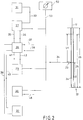
- the partial voltage U1 or the partial voltage U2 can be used to control and switch off the device. For this purpose, reference is first made to FIG. 2.
- the resistance track 24 of the potentiometer 22 is again shown as a development with 25 as a control range and 23 as a tap or grinder.
- the schematically represented circuit blocks designated 27, 28, 29 and 30 are part of the actual control electronics, which have the task of processing signals of the function blocks 31 and 32 and of the actual value potentiometer 22.
- Function block 31 is a setpoint generator which is set, for example, by pressing the "UP" key or the “DOWN” key. It supplies a setpoint current signal 33 of, for example, 4 to 20 mA, which is converted into a proportional voltage signal. This voltage signal and the actual value signal 34 of the absolute encoder (actual value potentiometer 22) are compared and the positive or negative control deviation is given to the output lines 35 and 36. Since the output signal of a discontinuous controller is discontinuous, a directional signal for the function block 28 is hereby generated in a simple manner, which controls the drive motor of the device via output lines 37 and 38, as will be described in more detail below.
- Function block 32 represents a terminal for key actuation, from which direction signals 39 and 40 are generated, just like function block 27. Together with the enable lines 41 and 42 from the function block 29, the output lines 37 and 38 of the function block 28 are activated by an AND function and thus control - see FIG. 5 - directional relays 43 and 44, and these in turn the reversing contactors 45 and 46 of the Motors 20
- the function block designated 30 in FIG. 2 stands for differentiators for the function dU / dt and monitors the movement of the device, for example 1.
- the differentiators have the task of switching off the motor 20 when the movement command for the armor 11 is set, if dU / dt against 0 or dU / dt against ⁇ is determined, which facts suggest serious defects.
- an optional position indicator 52 is shown as an option, on which the respective effective position of the device to be moved, for example the position of the lower edge 13 of the lowest slat 14 of a roller shutter 11, can be read .
- This display 52 can also be connected via a longer line 53 at a location remote from the drive or from the electronics, e.g. in a surveillance room.
- the controller 27 is designed so that not only the actual value 34 of the potentiometer 22, but also the setpoint 72 is constantly present. This is achieved as follows:
- the controller 27 is first separated by an electronic switch 27B (ES1) into two function blocks 27 (27A) and 27C (27C), of which function block 27A determines the control deviations and function block 27C converts them into digital direction signals 35 (eg A for OPEN) and 36 (eg Z for ZU) evaluates.
- ES1 electronic switch 27B
- function block 27A determines the control deviations
- function block 27C converts them into digital direction signals 35 (eg A for OPEN) and 36 (eg Z for ZU) evaluates.
- FB3 third function block 27D
- the voltages of the setpoint signals 70, 71 for the end positions of the roller door are obtained by the two setting trimmers 50 and 51 of two end position comparators designated 29A, 29B and by means of electronic switches 28A (ES2) and 28B (ES3) as setpoint SW1 or as setpoint SW2 activated.
- the setting potentiometers 50, 51 trim the switching range of the end position comparators outside the usual control range, since safety is essentially intended in the event of the control circuit failure.
- an externally supplied, constantly applied current setpoint signal (31) via the electronic switching stage 28 (US) can cause the switch 27B (ES1) to be closed.
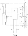
- FIG. 4 illustrates the overall context of the additional electronic safety switches (SS1 and SS2 in FIG. 3) in a simplified manner.
- the mode of action is as follows:
- the same supply voltage is present at the absolute encoder (actual value potentiometer 22) and the setting trimmers 50 and 51.
- the signal voltage 16 of the absolute encoder 22 is compared with the wiper voltages of the setting trimmers 50 and 51 and evaluated according to the principle of the Wheatston bridge by the function block 29, a comparator, as directional enable signals.
- the setting trimmers 50 and 51 are set so that the travel end positions of the absolute encoder 22 are adjusted in the respective bridge branch. This always happens when the grinder 23 of the absolute encoder driven by the movement of the device (e.g. the roller shutter movement) moves in the respective direction of travel until a bridge adjustment takes place.
- a bridge adjustment in each case blocks the direction and enable signals 41 or 42.
- the devices SS1 and SS2 are therefore safety limit switches, which still guarantee reliable end position switching of the motor if, e.g. in the event of a defect in the controller, travel values for the movable device would still be reported on the basis of the values of the setpoint generator 31.
- Fig. 5 shows a circuit diagram of the roller shutter control.
- the function blocks 45 and 46 represent the motor reversing contactors of the control. They are controlled by switch contacts of the function blocks 43 and 44 and the switch contact of the function block 47.
- the switching voltage is denoted by 49.
- Function blocks 28A and 28B are AND circuits with inputs A and Z or 35 and 36 from the three-point controller 27 or its function blocks 27C and the inputs SS1 and SS2 from the safety limit switches 41 and 42.
- Function block 47 essentially has the function of a safety relay which is controlled by the differentiating element 30. With the directional relays 43 and 44, it forms a series connection, so that in the event of malfunctions in the electronics or the absolute encoder 22, a reliable shutdown of the reversing contactors 34 and 35 is always ensured.
- the actual value voltage 34 is given directly to two differentiating elements 30A, 30B, of which one differentiating element 30A differentiates the input voltage from 0 (the level of the differentiated voltage on a not shown) Resistance is adjustable), and the other differentiator 30B differentiates the input voltage from ⁇ (the level of this differentiated voltage can also be determined by means of an adjusting resistor).
- a housing 55 is flanged to the so-called B-shield 64 of an electric motor 54.
- This housing 55 contains a reduction gear 56, preferably in the form of a planetary gear, which is coupled to the motor shaft 58 for rotational driving via plug-in coupling means 57.
- the gearbox output shaft 59 is connected via a shaft coupling 60 to the adjusting spindle 61 of a rotary potentiometer 62 so as to be rotationally driven.
- the entire device accommodated in the housing 55 can be plugged into the shaft end 58 of the motor 54 and flanged onto the B-plate 53.
- the electrical connection is then only to be made to the connection lugs 63 of the potentiometer 62.
- one of the simplest absolute encoders uses a rotary potentiometer with a slider path of just under 360 °
- the tap of the potentiometer is connected to a reduction gear, which is connected to the motor shaft or to the gear shaft of the drive or to the winding shaft of the device is.
- This reduction gear ensures that the number of revolutions of the motor shaft, the gear shaft or the winding shaft corresponding to the full opening stroke are converted into the maximum possible travel of the potentiometer spindle or the tap.
- the winding shaft of a roller shutter can require about 10 revolutions to move the roller shutter from the closed position to the open position. These 10 revolutions are then reduced by the gear so that the spindle of the potentiometer can only be safely inside their possible rotation path can be adjusted by the winding shaft.
- potentiometer is designed as a multi-turn or multi-turn potentiometer and its tap is connected directly to the motor shaft, to the transmission shaft or to the winding shaft of the device.
- potentiometers are available whose total adjustment path requires 10 revolutions of the adjusting spindle. This value is very favorable for roller shutters, because a large number of roller shutters of conventional dimensions require less than 10 revolutions of the winding shaft to wind up the shell.
- a cable pull potentiometer can also be provided as an absolute encoder, the free cable end of which is attached to or near the free edge of the movable device part.
- the drive of the grinder of the potentiometer by means of a rotationally driven part is omitted, and the adjustment path of the potentiometer is synchronized directly with the part of the device to be moved. This also enables direct movement monitoring of the moving part itself.
- potentiometer is mentioned in connection with the actual value encoder, it should be mentioned that other absolute encoders can also be used instead, although a potentiometer appears to be the component currently best considered for realizing the invention.
Landscapes
- Engineering & Computer Science (AREA)
- Structural Engineering (AREA)
- Physics & Mathematics (AREA)
- General Physics & Mathematics (AREA)
- Automation & Control Theory (AREA)
- Architecture (AREA)
- Civil Engineering (AREA)
- Operating, Guiding And Securing Of Roll- Type Closing Members (AREA)
Applications Claiming Priority (2)
| Application Number | Priority Date | Filing Date | Title |
|---|---|---|---|
| DE4341361 | 1993-12-04 | ||
| DE4341361 | 1993-12-04 |
Publications (2)
| Publication Number | Publication Date |
|---|---|
| EP0657795A2 true EP0657795A2 (fr) | 1995-06-14 |
| EP0657795A3 EP0657795A3 (fr) | 1996-09-04 |
Family
ID=6504179
Family Applications (1)
| Application Number | Title | Priority Date | Filing Date |
|---|---|---|---|
| EP94710011A Withdrawn EP0657795A3 (fr) | 1993-12-04 | 1994-12-02 | Dispositif pour la commande d'installations mobiles telles que des portes roulantes ou similaires. |
Country Status (2)
| Country | Link |
|---|---|
| EP (1) | EP0657795A3 (fr) |
| DE (1) | DE4442948A1 (fr) |
Cited By (3)
| Publication number | Priority date | Publication date | Assignee | Title |
|---|---|---|---|---|
| EP1130211A1 (fr) * | 2000-02-02 | 2001-09-05 | Vilaplana Lauri, Sonia | Dispositif d'entraínement pour volets roulant, jalousies ou autres semblables et méthode d'opération. |
| EP1319795A3 (fr) * | 2001-12-17 | 2004-02-04 | Becker-Antriebe GmbH | Système de commande pour un appareil d'entraínement de tubes dans une protection solaire ou un dispositif d'occultation |
| CN102494601A (zh) * | 2011-12-09 | 2012-06-13 | 中国钓具技术标准化(北仑海伯)研究中心 | 一种使用电位器测量家用电动窗位移的方法 |
Families Citing this family (3)
| Publication number | Priority date | Publication date | Assignee | Title |
|---|---|---|---|---|
| DE19630491C1 (de) * | 1996-07-29 | 1998-02-05 | Selve Ernst Gmbh Co Kg | Schaltungsanordnung zur Steuerung von elektromotorischen Antrieben für auf- und abwickelbare Behänge |
| ES2237170T3 (es) | 1999-10-08 | 2005-07-16 | Rwe Piller Gmbh | Dispositivo para el suministro de corriente sin interrupciones con una maquina electrica y un volante. |
| DE102015200521B4 (de) | 2015-01-15 | 2018-03-01 | Geze Gmbh | Automatischer Türantrieb und zugehöriges Betriebsverfahren |
Family Cites Families (2)
| Publication number | Priority date | Publication date | Assignee | Title |
|---|---|---|---|---|
| DE2824510C2 (de) * | 1978-06-03 | 1984-04-26 | Vierling, Oskar, Prof. Dr.Phil.Habil., 8553 Ebermannstadt | Vorrichtung zum Steuern der Bewegung eines angetriebenen Tores |
| EP0544262B1 (fr) * | 1991-11-25 | 1996-04-17 | Marantec Antriebs- Und Steuerungstechnik Gmbh & Co., Produktions Kg | Circuit pour surveiller un objet mouvant |
-
1994
- 1994-12-02 DE DE4442948A patent/DE4442948A1/de not_active Withdrawn
- 1994-12-02 EP EP94710011A patent/EP0657795A3/fr not_active Withdrawn
Cited By (5)
| Publication number | Priority date | Publication date | Assignee | Title |
|---|---|---|---|---|
| EP1130211A1 (fr) * | 2000-02-02 | 2001-09-05 | Vilaplana Lauri, Sonia | Dispositif d'entraínement pour volets roulant, jalousies ou autres semblables et méthode d'opération. |
| ES2190299A1 (es) * | 2000-02-02 | 2003-07-16 | Vilaplana Lauri Sonia | Dispositivo motoreductor de enrollamiento de persianas y toldos y metodo de operacion |
| EP1319795A3 (fr) * | 2001-12-17 | 2004-02-04 | Becker-Antriebe GmbH | Système de commande pour un appareil d'entraínement de tubes dans une protection solaire ou un dispositif d'occultation |
| CN102494601A (zh) * | 2011-12-09 | 2012-06-13 | 中国钓具技术标准化(北仑海伯)研究中心 | 一种使用电位器测量家用电动窗位移的方法 |
| CN102494601B (zh) * | 2011-12-09 | 2013-10-02 | 中国钓具技术标准化(北仑海伯)研究中心 | 一种使用电位器测量家用电动窗位移的方法 |
Also Published As
| Publication number | Publication date |
|---|---|
| EP0657795A3 (fr) | 1996-09-04 |
| DE4442948A1 (de) | 1995-06-08 |
Similar Documents
| Publication | Publication Date | Title |
|---|---|---|
| EP3361028B1 (fr) | Unité d'entraînement | |
| EP0703344B1 (fr) | Dispositif d'arrêt automatique d'un store à rouleau, notamment un volet roulant | |
| DE102004007883A1 (de) | Automatischer Torantrieb | |
| DE202009006587U1 (de) | Torantrieb mit zwei Motoren | |
| EP0561361B1 (fr) | Procédé et dispositif pour commander des actionneurs de porte | |
| DE102010014806B4 (de) | Torantriebsvorrichtung, damit versehener Gebäudeabschluss, Torsystem und Herstell- und Antriebsverfahren | |
| EP1091079A2 (fr) | Système de contrôle pour unités d'entraínement à moteur pour un dispositif d'occultation ou d'obscurcissement | |
| DE2824510C2 (de) | Vorrichtung zum Steuern der Bewegung eines angetriebenen Tores | |
| DE4442948A1 (de) | Vorrichtung zur Steuerung von beweglichen Einrichtungen wie Rolltoren o. dgl. | |
| EP2659077B1 (fr) | Procédé de fabrication et de fonctionnement d'un porte automatique et système de porte | |
| EP2298683A1 (fr) | Opérateur pour porte | |
| DE9106410U1 (de) | Antrieb für Türen, Tore oder Klappen | |
| EP0808986B1 (fr) | Dispositif de commande de portes | |
| EP0621390A2 (fr) | Dispositif électronique de contrôle pour contrôler des jalousies, volets roulants, marquises, rideaux, portes de garages et similaires | |
| DE102016102703B3 (de) | Torantriebsvorrichtung, überkopftor sowie betriebsverfahren hierfür | |
| DE102011107867B4 (de) | Verfahren zum Betrieb eines Gebäudeverschlusses | |
| DE4446920A1 (de) | Verdunkelungseinrichtung | |
| EP1083291B1 (fr) | Dispositif d'entraínement éléctrique pour volet roulant | |
| DE19644056C1 (de) | Elektrischer Garagentorantrieb | |
| DE29904106U1 (de) | Steuerungssystem einer Verdunkelungs- und/oder Sicherungsanlage | |
| DE9318568U1 (de) | Abschaltvorrichtung für endlagengesteuerte Einrichtungen | |
| DE20106870U1 (de) | Antrieb für Verschließelemente mit drehzahlvariablem Abtrieb | |
| DE69407465T2 (de) | Sicherheitsvorrichtung für eine Öffnung, zum Beispiel Rolladen | |
| DE10019123B4 (de) | Einrichtung zur Drehmomentbegrenzung und Überlastabschaltung von Antrieben mit einem Einphasenkurzschlußläufermotor, insbesondere für Rauch- und Wärmeabzüge | |
| EP3263815B1 (fr) | Entraînement de porte |
Legal Events
| Date | Code | Title | Description |
|---|---|---|---|
| PUAI | Public reference made under article 153(3) epc to a published international application that has entered the european phase |
Free format text: ORIGINAL CODE: 0009012 |
|
| AK | Designated contracting states |
Kind code of ref document: A2 Designated state(s): BE DE ES FR GB IE IT NL |
|
| PUAL | Search report despatched |
Free format text: ORIGINAL CODE: 0009013 |
|
| AK | Designated contracting states |
Kind code of ref document: A3 Designated state(s): BE DE ES FR GB IE IT NL |
|
| STAA | Information on the status of an ep patent application or granted ep patent |
Free format text: STATUS: THE APPLICATION IS DEEMED TO BE WITHDRAWN |
|
| 18D | Application deemed to be withdrawn |
Effective date: 19970305 |