EP0657841A1 - Détection de la position d'un crayon utilisant un capteur d'image à une dimension - Google Patents
Détection de la position d'un crayon utilisant un capteur d'image à une dimension Download PDFInfo
- Publication number
- EP0657841A1 EP0657841A1 EP94308882A EP94308882A EP0657841A1 EP 0657841 A1 EP0657841 A1 EP 0657841A1 EP 94308882 A EP94308882 A EP 94308882A EP 94308882 A EP94308882 A EP 94308882A EP 0657841 A1 EP0657841 A1 EP 0657841A1
- Authority
- EP
- European Patent Office
- Prior art keywords
- image
- active area
- reflecting means
- plane
- reflecting
- Prior art date
- Legal status (The legal status is an assumption and is not a legal conclusion. Google has not performed a legal analysis and makes no representation as to the accuracy of the status listed.)
- Withdrawn
Links
Images

Classifications
-
- G—PHYSICS
- G06—COMPUTING OR CALCULATING; COUNTING
- G06F—ELECTRIC DIGITAL DATA PROCESSING
- G06F3/00—Input arrangements for transferring data to be processed into a form capable of being handled by the computer; Output arrangements for transferring data from processing unit to output unit, e.g. interface arrangements
- G06F3/01—Input arrangements or combined input and output arrangements for interaction between user and computer
- G06F3/03—Arrangements for converting the position or the displacement of a member into a coded form
- G06F3/041—Digitisers, e.g. for touch screens or touch pads, characterised by the transducing means
- G06F3/042—Digitisers, e.g. for touch screens or touch pads, characterised by the transducing means by opto-electronic means
- G06F3/0428—Digitisers, e.g. for touch screens or touch pads, characterised by the transducing means by opto-electronic means by sensing at the edges of the touch surface the interruption of optical paths, e.g. an illumination plane, parallel to the touch surface which may be virtual
Definitions
- the present invention relates to sensing the position of an object in a plane and, more specifically, sensing the position of a stylus on a surface using a single camera and two mirrors.
- the sensing (detecting) technology must be lightweight, consume little electronic power, be durable and withstand electromagnetic interference from other parts of the computer.
- capturing handwriting requires the system to be accurate to within, for example, five thousandths of an inch. This level of accuracy is far more difficult to achieve than that required in other applications such as determining whether a finger is pointing to the "deposit" box or the "withdrawal” box on the touch screen of an automated teller machine. If the pen-sensing system makes even small errors, the computer might not be able to make fine distinctions, such as discriminating the letter "Z" from the number "2,” no matter how proficient the computer's handwriting-recognition software is. Without a highly precise mechanism for sensing the position of the stylus these computer systems will not reliably and accurately function.
- the position sensing mechanism In addition to reliability and accuracy, the position sensing mechanism must be cost effective, durable and, easy to use. Some technologies, for instance, require the stylus to be connected to the computer by a wire, while others allow for a stylus to be detached. In general, it is desirable for a stylus to be detachable from the computer and the sensing device in order to improve the system's flexibility. However, the cost of manufacturing the stylus should not be excessive since a detachable stylus may be easily misplaced.
- the voltage in this coating is made to vary gradually from the top to the bottom of the screen and from the left to the right of the screen.
- an electrical current flows through the stylus and is transmitted to the computer via a wire. Since the voltage varies across the screen, the amount of electricity flowing through the stylus will vary depending on where it touches the screen.
- This technology is inexpensive. However, this technology requires the stylus to be wired to the computer and to make contact with the screen in order for the stylus position to be detected.
- the coating is on the front of the screen, it is subject to wear.
- a second approach uses electromagnetic waves, essentially a faint radio transmission from the stylus to the computer or vice versa.
- a grid of wires behind the screen emits a signal which causes a circuit in the stylus, which is tuned to the signal frequency, to resonate and transmit a signal of its own.
- the computer stops transmitting and listens for the signal from the stylus.
- the position of the stylus is determined by the position of the wires in the grid which detect the signal emanating from the circuit in the stylus.
- This second approach can sense the stylus location before it touches the screen.
- the stylus need not be connected to the computer by a wire and may be an unpowered, passive circuit.
- this system is expensive, with a stylus costing $80 or more.
- the grid of wires behind the screen make it more difficult for screens to be backlit. Therefore, screens using this system are typically more difficult to read.
- a third approach is similar to the electromagnetic one, i.e., the second approach, but senses by electrostatic coupling rather than electromagnetic coupling.
- This system can also detect the stylus without requiring the stylus to contact the screen.
- the stylus must be active and therefore must either be wired to the computer or contain a battery. Styluses using this approach are less costly than those in the second approach, but they remain relatively expensive.
- the drawing surface must be specially designed in order to determine the stylus location. That is, in the first approach, the drawing surface is coated with an indium-tin oxide. In the second and third approaches, a grid of wires must be positioned beneath the drawing surface.
- the stylus should not require connection to the computer or to a drawing surface.
- the sensor should be compact while not requiring a special surface coating or an embedded wire grid.
- the system should be able to sense the position of the stylus before the stylus physically contacts an object such as a drawing surface. In fact, a drawing surface should not be required to determine the stylus position.
- the system should be durable and inexpensive to build and maintain.
- the present invention is an apparatus and method for determining the location of an object in an active area of a first plane.
- the apparatus includes a first reflecting device, disposed substantially perpendicular to the first plane at a periphery of the active area.
- the first reflecting device receives a first image of the object from the active area and reflects the first image back toward the active area substantially parallel to the first plane.
- a second reflecting device disposed substantially perpendicular to the first plane at a periphery of the active area, receives a second image of the object from the active area and reflects the second image back toward the active area substantially parallel to the first plane.
- the second reflecting device is disposed at a first angle which is less than one-hundred eighty degrees to the first reflecting device.
- the angle opens toward the active area and toward a detecting device.
- the detecting device is disposed in the first plane at a periphery of the active area opposite the first and second reflecting devices.
- the detecting device receives the first image and the second image and produces a signal indicating the position of the first and second images.
- the invention is implemented in a notebook computer system.
- the invention precisely determines the location of the stylus without requiring the stylus to be connected to the sensing device and without requiring a writing tablet or other surface beneath the stylus.
- FIGURE 1 is a top view diagram illustrating the operation of a preferred embodiment of the present invention.
- FIGURE 2 is a side view diagram illustrating the operation of the preferred embodiment of the present invention.
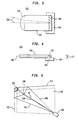
- FIGURE 3 is a top cross-sectional view illustrating the operation of a sensor of the present invention.
- FIGURE 4 is a side cross-sectional view illustrating the operation of the sensor of the present invention.
- FIGURE 5 is a diagram illustrating the operation of an alternate embodiment of the present invention having an obtuse angle between the mirrors.
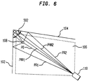
- FIGURE 6 is a diagram illustrating the operation of an alternate embodiment of the present invention having an acute angle between the mirrors.
- the present invention is an apparatus and method for sensing the position of an object, e.g., a stylus, in a two-dimensional plane using a one-dimensional sensing device.
- the invention is implemented in a notebook computer.
- the stylus need not be tethered to the computer system. Stylus position can be determined without requiring the stylus to contact any portion of the computer system.
- a special stylus tablet is not required.
- the invention includes two reflective devices.
- these reflective devices are mirrors 102, 104, which are perpendicularly coupled to each other at one end.
- a viewing plane 116 is defined by the drawing sheet of FIG. 1.
- the viewing plane 116 is substantially perpendicular to the reflecting surface of the mirrors 102, 104.
- An active area 106 of the system is in the viewing plane 116.
- a stylus 108 is placed into the viewing plane 116.
- Numerous images e.g., between two and five images depending on the angle between the mirrors 102, 104 (described below), are received by a single image sensing device 110.
- the image sensing device 110 is positioned in the viewing plane 116. Image sensing device 110 then determines the two dimensional position of the stylus 108 in the viewing plane 116 based on the received images.
- Each mirror 102, 104 has a reflecting material on the surface facing the active area 106 to minimize refraction errors.
- a mirror having a glass surface, such that a ray of light must enter the glass before being reflected, can be used in the present invention.
- the reflective coating be on the surface nearest the active area 106.
- the mirrors 102, 104 are perpendicularly coupled such that the reflecting surfaces are perpendicular to the viewing plane 116 defining the active area 106.
- the reflective surfaces of the mirrors 102, 104 are substantially flat and are long enough to ensure that all reflections of a stylus 108, positioned in an active area 106, reach the sensing device 110.
- the height of the mirrors 102, 104 can be small because the viewing plane 116 defining the active area 106 is perpendicular to the reflecting surface of each mirror.
- a stylus which is complex and/or expensive.
- the stylus 108 of the present invention is neither complex nor expensive.
- a pen-light e.g. Radio Shack catalog number 61-2538
- Alternate embodiments of the stylus include a pencil or a finger. These embodiments are discussed below.
- the sensing device is a line-scan camera which forms a one-dimensional image of the active area 106 within the viewing plane 116.
- the sensing device 110 will now be discussed with reference to FIG. 3 and FIG. 4.
- the image sensing device 110 consists of a projective element 302, and a sensing element 304.
- the projective element can be a pinhole or an optical system consisting of one or more lenses and/or mirrors.
- the projective element forms an optical one-dimensional image of the active area 106 within the sensor element 304 by projecting a perspective projection from a two-dimensional plane 116 to a one-dimensional line 402.
- the view angle of the projective element 302 be at least 90 degrees, to cover a quadrilateral formed between the two mirrors and the optical center of the sensing device 110.
- this quadrilateral is the active area 106.
- the sensing device 110 is a line-scan imaging device, sometimes referred to as a linear imaging device (LID), for example a linear charged coupled device (CCD) array.
- LID linear imaging device
- CCD linear charged coupled device
- Its face plate contains a linear sensor, i.e., a line of light sensing elements. A one-dimensional image is projected onto its sensing elements and is converted into analog electrical signals.
- the analog output of the sensing element is converted to a digital format within the sensing element by a processing device (not shown), or by a separate analog-to-digital conversion device (not shown).
- a processing device not shown
- a separate analog-to-digital conversion device not shown
- a preferred configuration of the sensing device 110 consists of a linear CCD sensor 304, for example, a Fairchild CCD143A or CCD145, and a projective element 302 that projects a one-dimensional image at a right angle to the viewing plane 116.
- the projective element 302 would consist of a lens system 310 having a focal length of approximately 12mm whose optical axis lies in the viewing plane 116.
- the sensing device 110 includes a planar mirror 308 oriented at approximately 45 degrees to the viewing plane 116. This planar mirror 308 projects a one dimensional image onto the face plate 402 of the CCD sensor 304. Typically, the face plate 402 is parallel to the viewing plane 116 and slightly below it. The face plate 402 is also orthogonal to the optical axis of the lens.
- the sensing device 110 senses four images if the stylus 108 is in the active area 106 of the viewing plane 116.
- a stylus 108 when a stylus 108 is placed within the active area 106 four images are received by the sensing device 110. Four images are received by the sensing device because light emitting from the stylus 108 can enter the sensing device via four distinct paths. An illustration of the light paths is shown in FIG. 1.
- Light emitting from the stylus enters the sensing device 110: (1) directly via path PD, which is termed the direct image; (2) by reflecting off mirror 102 via path PR1, which is termed a single reflected image; (3) by reflecting off mirror 104 via path PR2, which is also termed a single reflected image; and (4) by reflecting off both mirror 104 and mirror 102 via path PRR, which is termed a double reflected image.
- the sensing device 110 outputs a vector of digital electrical signals representing a one-dimensional image of the images from the two-dimensional active area 106.
- a vector of digital electrical signals representing a one-dimensional image of the images from the two-dimensional active area 106.
- a processor receives the vector of digital electrical signals representing the images of the stylus 108, output from the sensing device 110.
- the processor compares the vector values with a fixed threshold value T1. Pixels having a value above this threshold are called “white”.
- the "white” pixels are represented by a binary "1”. Pixels whose value is below this threshold are called “black”.
- the white pixels are combined into maximally connected regions or runs.
- a run is a continuous chain of white pixels. The length of the run is defined by the number of pixels in the run. Runs shorter than a threshold T2 are eliminated. The value of T2 depends upon the resolution of the sensing device. Each run longer than T2 represents one highlight.
- the position of a highlight in the 1-D image is computed with sub-pixel accuracy, by fitting a unimodal function, described below, to the values of the pixels in the run. The location of a mathematical mode of the run is then determined. Typical choices for this unimodal function are a parabola or a gaussian function. It will be apparent to one skilled in the relevant art as to how these functions are applied to the pixel values in the run. Using the above process, the processor determines a set of highlight positions, each position represented, for example, as a rational number ranging from 1 to N (N being equal to the number of pixels representing the one-dimensional image of the active area 106).
- the light rays received from each image must be traced back to the stylus 108. This can be done in many ways.
- One technique for determining the stylus position 108 is described below. In the preferred embodiment four highlights exist, as described above. Each highlight point is a one-dimensional representation of a two-dimensional line in the plane of the active area 106. The locations of the mirrors are known. Therefore, the reflected path of each ray of light can be determined. The position where all four paths intersect is the stylus location.
- the preferred technique for calculating the stylus position is detailed below.
- a cartesian coordinate system is chosen to represent the plane of the active area 106.
- the origin of the coordinate system is identified by reference number 112.
- the positive x-axis extends toward the sensing device 110, i.e. to the right, the positive y-axis extends along the left mirror, i.e., upwards.
- the line between the sensing device center and the point where the two mirrors meet will be called the diagonal axis 114.
- a highlight position represents a single ray of light entering the sensing device 110.
- This ray can be represented as a 2-D line on the viewing plane 116.
- the equation of this line is obtained from calibration parameters of the sensing device 110. These parameters can be determined from a measurement of the values x, y, and u, using procedures which is incorporated herein by reference described in the book, O.D. Faugeras, Three-Dimensional Computer Vision , MIT Press, Cambridge, MA, 1992 (restricted to a plane). While it will be apparent to one skilled in the relevant art how these values are determined, a brief discussion is provided below.
- the following sensing device model is used. If the position P of the stylus in the active area 108 is a point on the viewing plane 116 with coordinates x and y, then the image of P will be a point with position "u" in the 1-D image.
- the value of u must be between 1 and N as defined above.
- the values a, b, c, d, and e, in Equation [1] are calibration parameters of the sensing device 110, which are assumed to remain constant in the preferred embodiment.
- the relationship between x, y, and u may vary from that given in Equation [1] since lenses distort the highlight position in the one-dimensional image. This distortion may be accounted for by replacing u in Equation [1] with a non-linear lens distortion function, f(u) which is constant.for a given lens.
- f(u) non-linear lens distortion function
- the line whose equation is given by Equation [2] is the line which represents the trace of a light ray entering the sense array 110.
- the stylus position 108 is located on the trace of the direct image PD, discussed above, which can be represented by Equation [2].
- Equation [8] is used to solve for the path of these two image paths PR1, PR2.
- the point at which the two paths intersect is the stylus position 108.
- the trace of the other images i.e., the direct image trace PD and the double reflected image trace PRR are determined.
- Equation [8] represents the path of the light ray L2 before reflecting off of a mirror and entering the sensing device 110. In the preferred embodiment it is also necessary to determine the trace of a light ray which enters the sensing device 110 after reflecting off both mirrors 102, 104, i.e., path PRR of FIG. 1.
- each image is assumed to be a double reflected image and the calculations proceed under this assumption.
- the assumption having the lowest error, discussed below, is deemed to be the double reflected image.
- L1 (whose path is described by Equation [3]), which enters the sense device 110, is assumed to be a result of a double reflection from two mirrors, then a line L3 describes this ray before the first of the two reflections.
- the path of L3 is determined as follows. M1 represents a line describing the position of the left mirror 102, and M2 represents a line describing the position of the upper mirror 104.
- the corner point between the two mirrors [cx, cy] is the intersection of the lines M1 and M2. This intersection can be found by solving the line Equations M1 and M2 for x and y.
- T ⁇ 1 If T ⁇ 1, then the light ray emanating from the stylus reflects first off of mirror 102 and then off of mirror 104. If T > 1, then the light ray emanating from the stylus reflects first off of mirror 104 and then off of mirror 102. If T is approximately equal to 1 then the ray either-comes directly from the source, i.e, path PD, or the light ray is a double reflection which overlaps with the path of the direct ray PD. In both situations the ray is treated as if it were a direct ray, PD, and the double reflection computation need not continue.
- the path of the light ray before the first reflection, L3 can be calculated by using the technique described above.
- the pre-reflected path can be determined by first calculating the path of the light after a single reflection, using Equation [8], and then using this result to calculate the path of the light before the first reflection.
- the number of identified highlights may be smaller than the number of images. This occurs because within a certain region near the diagonal axis 114, the highlight from a double reflection will merge with the direct image highlight, discussed above. This causes the direct image and the double reflected image to appear together in the one-dimensional sensor and therefore the two images appear as only one blurred image in the sensing device 110. If the stylus position 108 is close to one of the mirrors 102, 104 then a single reflection image may merge with the direct image. This overlapping of the direct image and a single reflected image is avoided by separating the active area 106 from the mirrors 102, 104 as is shown in FIG. 1.
- the highlights corresponding to the left-most and right-most rays from the perspective of the sensing device 110 will be referred to as left-most and right-most highlights (images), respectively.
- the double reflected image and the direct image overlap only three highlights are identified by the computer.
- the left-most highlight represents the single reflected image which reflects off of mirror 102.
- the right-most highlight represents the single reflected image which reflects off of mirror 104.
- the middle image is the direct image.
- the path of the pre-reflected path is determined for each highlight as discussed above.
- the left-most highlight and the right-most highlight represent single reflected images. Difficulty is encountered in attempting to determine which of the two middle highlights represents the direct image and which of the two middle highlights represents the double reflected image.
- One technique for identifying the double reflected image from the direct image is to create two scenarios, each being an overdetermined system of four linear equations L1, L2, L3, and L4, with two unknowns. The first two of these equations are the traced single reflections L1 and L2. The remaining two equations are obtained from the two middle highlights. In the first scenario, we treat the first of the two middle highlights as a direct image. In the second scenario, we treat the second of the middle highlights as a direct image.
- the position of the stylus 108 i.e., locations x and y, is determined using a single sensing device and two mirrors.
- Other techniques for determining the stylus location based on the information provided by the sensing device 110 will be apparent to those skilled in the relevant art.
- This technique can be extended to determine the position of multiple objects in an active area 106. Additionally, the orientation of objects may be detected. Another embodiment senses the movement of an object through the active area 106. Such a movement can be a finger, or multiple fingers, moving through the active area. The computer may be designed to interpret such a motion, e.g., sweeping a finger through the active area may equate to an "erase display" command.
- the stylus of the present invention need not be coupled or tethered to the sensing device 110 or to the computer (not shown).
- the present invention does not require a light based stylus.
- a passive stylus such as a pen, a pencil or even a finger can be used.
- the edges of the active area 106 which are opposite the mirrors 102, 104 should be lined with contrasting background strips.
- a good combination is a dark background with a light colored stylus, or a stylus with a reflective spherical tip to enable a sharper distinction between the stylus and the background.
- Another embodiment uses a passive stylus and two diffused light sources.
- the light sources are placed along the edges of the active area 106 which are opposite the mirrors 102, 104. These light sources will form shadows of the stylus which will be detected by the sensing device 110.
- Many opaque items e.g., a pen, a pencil or a finger, can be used as a passive stylus. In this situation the computer will determine the highlight position based on a run of black pixels instead of a run of white pixels.
- the sensing device 110 may be advantageous to reduce the number of images the sensing device 110 receive. If the double reflected image is eliminated then only three images are received by the sensing device 110. The trace of these three images are immediately known, i.e., the left-most image is a single reflected image from mirror 102, the right-most image is a single reflected image from mirror 104 and the middle image is the direct image.
- the double reflected image may be eliminated by placing a polarizing filter over each of mirrors 102, 104 such that the relative polarization angle between the two filters is ninety degrees. The detailed structure and operation of these polarizing filters will be apparent to persons skilled in the relevant art.
- An alternate embodiment of the present invention is a technique for efficiently determining which of the middle images is the double reflected image.
- Two radiation intensity reducing filters are placed adjacent the mirrors 102, 104 or are built into the mirrors 102, 104.
- the sensing device senses the images, the direct image will have the highest intensity and the double reflected image will have the lowest intensity.
- the intensity of the light emitting from the stylus is reduced twice, once by each mirror, for the double reflected image.
- the sensing device 110 can detect the intensity of the radiation it is receiving. Therefore, the middle highlight having the lower intensity represents the double reflected image.
- the detailed structure and operation of the radiation reducing filters will be apparent to persons skilled in the relevant art. Instead of utilizing radiation intensity reducing filters, a similar effect results from using two polarizing filter having a relative polarization angle between zero and ninety degrees.
- the mirrors 102, 104 are positioned such that the reflective surface of each mirror 102, 104 is perpendicular to the viewing plane 116.
- one or both mirrors may be positioned such that the planes which are perpendicular to reflective surface of each mirror do not align with each other or with the viewing plane 116. An example of this can be seen in FIG. 2.
- FIG. 2 represent a side view of the present invention, i.e., looking directly into mirror 102.
- the viewing plane 116 which includes the active area 106, is perpendicular to the reflecting surface of the mirrors 102 and 104.
- this is not required.
- one mirror 102 is aligned according to the preferred embodiment, i.e., parallel to the Z-axis.
- the second mirror 104 is not aligned perpendicularly to the viewing plane 116, i.e., angle 204 is not ninety degrees.
- angle 204 diverges from ninety degrees the height of the mirrors must increase in order to properly reflect a previously reflected image.
- the height 404, in FIG. 4, of the receiving portion of the sensing device 110, i.e., the projective element 302 must increase to ensure that all images will be properly received by the sensing means 110.
- the mirrors are perpendicularly coupled in the X-Y plane.
- the angle of connection, angle 502 in FIG. 5 diverges from ninety degrees.
- the mirror angle 502 can vary significantly from ninety degrees.
- the mirror connection angle 502 is obtuse, i.e., greater than ninety degrees.
- having an obtuse mirror angle 502 is an advantage over having a perpendicular mirror angle.
- Such an advantageous situation occurs when a direct image highlight is merged with a double reflection. This occurs when the stylus 108 is positioned on or near the diagonal axis 114.
- the sensing device 110 senses a blurred image, discussed above. This blurred image may result in a significant error when determining the stylus position.
- the mirrors 102, 104 may be positioned such that an obtuse mirror angle 502 is formed.
- the technique for determining the stylus position 108 when the mirror angle 502 is obtuse is the same as that described above in the preferred embodiment. In some situations only three images may appear. Therefore, in these situations it is necessary to solve for the two unknowns, x and y, with three equations. A technique for solving this system is described above.
- the mirror angle 502 may also be acute, as shown in FIG. 6.
- a fifth image may be detected by the sensing device 110.
- This fifth image results from two images having double reflected traces, i.e., PRR1 and PRR2.
- the technique for determining the stylus position 108 when the sensing device 110 receives five images is similar to the technique described above when the sensing device 110 receives four images. Instead of solving two scenarios, three scenarios are solved. It is known that the left-most image and the right-most image are both traces of single reflected images. In each of the three scenarios, a different middle image is chosen as the direct image. Each scenario requires a solution to an overdetermined system of linear equations consisting of five equations, one for each image, having two unknowns, x and y. Therefore, as discussed above, each of the scenarios will have a solution and an associated error. The solution having the smallest associated error is selected as the stylus position.
- filters can be used to distinguish double reflections, as described above.
- the sensing device 110 As the mirror angle 502 decreases, more than five images may be received by the sensing device 110. These additional images may be the result of double reflections, triple reflections or higher-order reflections.
- the object position may be determined using the techniques described above.
- one or more images may be obscured, for example, if a user positions a hand on a tablet, i.e., within the viewing plane 116. If such a possibility is accounted for, the rule discussed above stating that the left-most and right-most highlights correspond to single reflections can not be used.
- One solution to this problem is found by forming scenarios that allow for some highlights to be obscured, and solving these scenarios as shown above.
- An alternative is to use filters for identification of highlights as described above.
- An additional embodiment employs an active stylus which is equipped with a pressure sensor that relates light source intensity to the stylus pressure on the tablet.
Landscapes
- Engineering & Computer Science (AREA)
- General Engineering & Computer Science (AREA)
- Theoretical Computer Science (AREA)
- Human Computer Interaction (AREA)
- Physics & Mathematics (AREA)
- General Physics & Mathematics (AREA)
- Position Input By Displaying (AREA)
Applications Claiming Priority (2)
| Application Number | Priority Date | Filing Date | Title |
|---|---|---|---|
| US08/163,419 US5484966A (en) | 1993-12-07 | 1993-12-07 | Sensing stylus position using single 1-D image sensor |
| US163419 | 1993-12-07 |
Publications (1)
| Publication Number | Publication Date |
|---|---|
| EP0657841A1 true EP0657841A1 (fr) | 1995-06-14 |
Family
ID=22589944
Family Applications (1)
| Application Number | Title | Priority Date | Filing Date |
|---|---|---|---|
| EP94308882A Withdrawn EP0657841A1 (fr) | 1993-12-07 | 1994-11-30 | Détection de la position d'un crayon utilisant un capteur d'image à une dimension |
Country Status (4)
| Country | Link |
|---|---|
| US (1) | US5484966A (fr) |
| EP (1) | EP0657841A1 (fr) |
| JP (1) | JPH07200158A (fr) |
| CA (1) | CA2118270A1 (fr) |
Cited By (27)
| Publication number | Priority date | Publication date | Assignee | Title |
|---|---|---|---|---|
| WO2005034027A1 (fr) * | 2003-10-09 | 2005-04-14 | Smart Technologies Inc. | Appareil pour la determination de la localisation d'un pointeur au sein d'une region d'interet |
| US7619617B2 (en) | 2002-11-15 | 2009-11-17 | Smart Technologies Ulc | Size/scale and orientation determination of a pointer in a camera-based touch system |
| US7643006B2 (en) | 2003-09-16 | 2010-01-05 | Smart Technologies Ulc | Gesture recognition method and touch system incorporating the same |
| CN101866244A (zh) * | 2009-04-20 | 2010-10-20 | 北京汇冠新技术股份有限公司 | 一种触摸定位装置 |
| CN101697105B (zh) * | 2009-10-26 | 2011-09-14 | 广东威创视讯科技股份有限公司 | 一种摄像式触摸检测定位方法及摄像式触摸检测系统 |
| USRE42794E1 (en) | 1999-12-27 | 2011-10-04 | Smart Technologies Ulc | Information-inputting device inputting contact point of object on recording surfaces as information |
| US8055022B2 (en) | 2000-07-05 | 2011-11-08 | Smart Technologies Ulc | Passive touch system and method of detecting user input |
| US8089462B2 (en) | 2004-01-02 | 2012-01-03 | Smart Technologies Ulc | Pointer tracking across multiple overlapping coordinate input sub-regions defining a generally contiguous input region |
| EP2402844A1 (fr) * | 2010-06-29 | 2012-01-04 | Sony Ericsson Mobile Communications AB | Dispositifs électroniques incluant des écrans interactifs et procédés associés et produits de programme informatique |
| USRE43084E1 (en) | 1999-10-29 | 2012-01-10 | Smart Technologies Ulc | Method and apparatus for inputting information including coordinate data |
| US8094137B2 (en) | 2007-07-23 | 2012-01-10 | Smart Technologies Ulc | System and method of detecting contact on a display |
| US8115753B2 (en) | 2007-04-11 | 2012-02-14 | Next Holdings Limited | Touch screen system with hover and click input methods |
| US8120596B2 (en) | 2004-05-21 | 2012-02-21 | Smart Technologies Ulc | Tiled touch system |
| US8149221B2 (en) | 2004-05-07 | 2012-04-03 | Next Holdings Limited | Touch panel display system with illumination and detection provided from a single edge |
| US8274496B2 (en) | 2004-04-29 | 2012-09-25 | Smart Technologies Ulc | Dual mode touch systems |
| US8289299B2 (en) | 2003-02-14 | 2012-10-16 | Next Holdings Limited | Touch screen signal processing |
| US8339378B2 (en) | 2008-11-05 | 2012-12-25 | Smart Technologies Ulc | Interactive input system with multi-angle reflector |
| US8384693B2 (en) | 2007-08-30 | 2013-02-26 | Next Holdings Limited | Low profile touch panel systems |
| US8405637B2 (en) | 2008-01-07 | 2013-03-26 | Next Holdings Limited | Optical position sensing system and optical position sensor assembly with convex imaging window |
| US8432377B2 (en) | 2007-08-30 | 2013-04-30 | Next Holdings Limited | Optical touchscreen with improved illumination |
| US8456447B2 (en) | 2003-02-14 | 2013-06-04 | Next Holdings Limited | Touch screen signal processing |
| US8456451B2 (en) | 2003-03-11 | 2013-06-04 | Smart Technologies Ulc | System and method for differentiating between pointers used to contact touch surface |
| US8508508B2 (en) | 2003-02-14 | 2013-08-13 | Next Holdings Limited | Touch screen signal processing with single-point calibration |
| US8692768B2 (en) | 2009-07-10 | 2014-04-08 | Smart Technologies Ulc | Interactive input system |
| US8902193B2 (en) | 2008-05-09 | 2014-12-02 | Smart Technologies Ulc | Interactive input system and bezel therefor |
| CN105335092A (zh) * | 2015-11-12 | 2016-02-17 | 广州视睿电子科技有限公司 | 实现平板人机交互的方法及系统 |
| US9442607B2 (en) | 2006-12-04 | 2016-09-13 | Smart Technologies Inc. | Interactive input system and method |
Families Citing this family (85)
| Publication number | Priority date | Publication date | Assignee | Title |
|---|---|---|---|---|
| JP3357175B2 (ja) * | 1994-04-13 | 2002-12-16 | 株式会社ワコム | 光学的位置検出方法 |
| JP3819654B2 (ja) * | 1999-11-11 | 2006-09-13 | 株式会社シロク | 指示体の識別機能を有する光デジタイザ |
| ATE490501T1 (de) * | 2000-07-05 | 2010-12-15 | Smart Technologies Ulc | Kamerabasiertes berührungssystem und verfahren |
| US7203383B2 (en) * | 2001-02-22 | 2007-04-10 | Thinkpen Llc | Handwritten character recording and recognition device |
| DE60119393T2 (de) * | 2001-02-22 | 2007-04-19 | ThinkPen LLC, Madison | Einrichtung zum aufzeichnen und erkennen handschriftlicher zeichen |
| CN100511115C (zh) * | 2002-03-13 | 2009-07-08 | 平蛙实验室股份公司 | 触摸板以及与触摸板一起使用的触笔和操作触摸板的方法 |
| US20030214490A1 (en) * | 2002-05-20 | 2003-11-20 | Gateway, Inc. | Stylus providing variable line width as a function of pressure |
| US6977187B2 (en) * | 2002-06-19 | 2005-12-20 | Foster-Miller, Inc. | Chip package sealing method |
| US7080545B2 (en) * | 2002-10-17 | 2006-07-25 | Advanced Technology Materials, Inc. | Apparatus and process for sensing fluoro species in semiconductor processing systems |
| US7203384B2 (en) * | 2003-02-24 | 2007-04-10 | Electronic Scripting Products, Inc. | Implement for optically inferring information from a planar jotting surface |
| EP1604271A2 (fr) * | 2003-03-12 | 2005-12-14 | O-Pen ApS | Detecteur de rayonnement multitache |
| CN1777859B (zh) * | 2003-03-12 | 2010-04-28 | 平蛙实验室股份公司 | 确定射线发射单元位置的系统和方法 |
| US20050057533A1 (en) * | 2003-08-28 | 2005-03-17 | Yong Liu | Detecting stylus location using single linear image sensor |
| US7442914B2 (en) * | 2003-09-12 | 2008-10-28 | Flatfrog Laboratories Ab | System and method of determining a position of a radiation emitting element |
| EP1665024B1 (fr) | 2003-09-12 | 2011-06-29 | FlatFrog Laboratories AB | Systeme et procede pour determiner la position d'un element de diffusion/reflexion de rayonnement |
| US7298367B2 (en) * | 2003-11-25 | 2007-11-20 | 3M Innovative Properties Company | Light emitting stylus and user input device using same |
| US20050110777A1 (en) * | 2003-11-25 | 2005-05-26 | Geaghan Bernard O. | Light-emitting stylus and user input device using same |
| US7088440B2 (en) * | 2003-12-22 | 2006-08-08 | Electronic Scripting Products, Inc. | Method and apparatus for determining absolute position of a tip of an elongate object on a plane surface with invariant features |
| US7348969B2 (en) * | 2003-12-30 | 2008-03-25 | 3M Innovative Properties Company | Passive light stylus and user input device using same |
| US20050156915A1 (en) * | 2004-01-16 | 2005-07-21 | Fisher Edward N. | Handwritten character recording and recognition device |
| US7961909B2 (en) | 2006-03-08 | 2011-06-14 | Electronic Scripting Products, Inc. | Computer interface employing a manipulated object with absolute pose detection component and a display |
| US9229540B2 (en) | 2004-01-30 | 2016-01-05 | Electronic Scripting Products, Inc. | Deriving input from six degrees of freedom interfaces |
| US7826641B2 (en) * | 2004-01-30 | 2010-11-02 | Electronic Scripting Products, Inc. | Apparatus and method for determining an absolute pose of a manipulated object in a real three-dimensional environment with invariant features |
| US8542219B2 (en) * | 2004-01-30 | 2013-09-24 | Electronic Scripting Products, Inc. | Processing pose data derived from the pose of an elongate object |
| US7232986B2 (en) * | 2004-02-17 | 2007-06-19 | Smart Technologies Inc. | Apparatus for detecting a pointer within a region of interest |
| US7492357B2 (en) * | 2004-05-05 | 2009-02-17 | Smart Technologies Ulc | Apparatus and method for detecting a pointer relative to a touch surface |
| US7746321B2 (en) | 2004-05-28 | 2010-06-29 | Erik Jan Banning | Easily deployable interactive direct-pointing system and presentation control system and calibration method therefor |
| US20060028457A1 (en) * | 2004-08-08 | 2006-02-09 | Burns David W | Stylus-Based Computer Input System |
| US9285897B2 (en) | 2005-07-13 | 2016-03-15 | Ultimate Pointer, L.L.C. | Easily deployable interactive direct-pointing system and calibration method therefor |
| US20070205994A1 (en) * | 2006-03-02 | 2007-09-06 | Taco Van Ieperen | Touch system and method for interacting with the same |
| US20090213093A1 (en) * | 2008-01-07 | 2009-08-27 | Next Holdings Limited | Optical position sensor using retroreflection |
| US20090207144A1 (en) * | 2008-01-07 | 2009-08-20 | Next Holdings Limited | Position Sensing System With Edge Positioning Enhancement |
| CN101261557B (zh) * | 2008-04-30 | 2011-09-14 | 北京汇冠新技术股份有限公司 | 一种用于触摸屏的图像传感装置 |
| US20090278816A1 (en) * | 2008-05-06 | 2009-11-12 | Next Holdings Limited | Systems and Methods For Resolving Multitouch Scenarios Using Software Filters |
| US20090278794A1 (en) * | 2008-05-09 | 2009-11-12 | Smart Technologies Ulc | Interactive Input System With Controlled Lighting |
| US20090277697A1 (en) * | 2008-05-09 | 2009-11-12 | Smart Technologies Ulc | Interactive Input System And Pen Tool Therefor |
| US8730169B2 (en) * | 2009-10-29 | 2014-05-20 | Pixart Imaging Inc. | Hybrid pointing device |
| US8581848B2 (en) | 2008-05-13 | 2013-11-12 | Pixart Imaging Inc. | Hybrid pointing device |
| US20100079385A1 (en) * | 2008-09-29 | 2010-04-01 | Smart Technologies Ulc | Method for calibrating an interactive input system and interactive input system executing the calibration method |
| EP2353069B1 (fr) * | 2008-10-02 | 2013-07-03 | Next Holdings Limited | Capteurs optiques stéréos pour résoudre un toucher multiple dans un système de détection de toucher |
| SE533704C2 (sv) | 2008-12-05 | 2010-12-07 | Flatfrog Lab Ab | Pekkänslig apparat och förfarande för drivning av densamma |
| US20100229090A1 (en) * | 2009-03-05 | 2010-09-09 | Next Holdings Limited | Systems and Methods for Interacting With Touch Displays Using Single-Touch and Multi-Touch Gestures |
| US8681124B2 (en) * | 2009-09-22 | 2014-03-25 | Microsoft Corporation | Method and system for recognition of user gesture interaction with passive surface video displays |
| US20110095977A1 (en) * | 2009-10-23 | 2011-04-28 | Smart Technologies Ulc | Interactive input system incorporating multi-angle reflecting structure |
| US8581847B2 (en) | 2009-10-29 | 2013-11-12 | Pixart Imaging Inc. | Hybrid pointing device |
| US20110199387A1 (en) * | 2009-11-24 | 2011-08-18 | John David Newton | Activating Features on an Imaging Device Based on Manipulations |
| US20110221666A1 (en) * | 2009-11-24 | 2011-09-15 | Not Yet Assigned | Methods and Apparatus For Gesture Recognition Mode Control |
| EP2507683A1 (fr) * | 2009-12-04 | 2012-10-10 | Next Holdings Limited | Procédés et systèmes de détection de position à l'aide d'un volume interactif |
| US8711125B2 (en) * | 2010-02-04 | 2014-04-29 | Hong Kong Applied Science And Technology Research Institute Co. Ltd. | Coordinate locating method and apparatus |
| US8937612B2 (en) * | 2010-02-04 | 2015-01-20 | Hong Kong Applied Science And Technology Research Institute Co. Ltd. | Coordinate locating method, coordinate locating device, and display apparatus comprising the coordinate locating device |
| US20110193969A1 (en) * | 2010-02-09 | 2011-08-11 | Qisda Corporation | Object-detecting system and method by use of non-coincident fields of light |
| US20110234542A1 (en) * | 2010-03-26 | 2011-09-29 | Paul Marson | Methods and Systems Utilizing Multiple Wavelengths for Position Detection |
| US8760403B2 (en) | 2010-04-30 | 2014-06-24 | Pixart Imaging Inc. | Hybrid human-interface device |
| US8648836B2 (en) | 2010-04-30 | 2014-02-11 | Pixart Imaging Inc. | Hybrid pointing device |
| TWI480784B (zh) * | 2011-06-21 | 2015-04-11 | Pixart Imaging Inc | 一種光學觸控系統及其計算物件座標方法 |
| TWI460635B (zh) * | 2011-09-01 | 2014-11-11 | Pixart Imaging Inc | 光學觸控系統、光學裝置及其定位方法 |
| CN102981681B (zh) * | 2011-09-06 | 2015-08-05 | 原相科技股份有限公司 | 光学触控系统、光学装置及其定位方法 |
| US9105211B2 (en) * | 2012-03-13 | 2015-08-11 | Samsung Electronics Co., Ltd | Portable projector and image projecting method thereof |
| US9754357B2 (en) * | 2012-03-23 | 2017-09-05 | Panasonic Intellectual Property Corporation Of America | Image processing device, stereoscoopic device, integrated circuit, and program for determining depth of object in real space generating histogram from image obtained by filming real space and performing smoothing of histogram |
| US10168835B2 (en) | 2012-05-23 | 2019-01-01 | Flatfrog Laboratories Ab | Spatial resolution in touch displays |
| US10019113B2 (en) | 2013-04-11 | 2018-07-10 | Flatfrog Laboratories Ab | Tomographic processing for touch detection |
| US9874978B2 (en) | 2013-07-12 | 2018-01-23 | Flatfrog Laboratories Ab | Partial detect mode |
| US10126882B2 (en) | 2014-01-16 | 2018-11-13 | Flatfrog Laboratories Ab | TIR-based optical touch systems of projection-type |
| WO2015108479A1 (fr) | 2014-01-16 | 2015-07-23 | Flatfrog Laboratories Ab | Couplage de lumière dans les systèmes tactiles optiques basés sur la tir |
| US10161886B2 (en) | 2014-06-27 | 2018-12-25 | Flatfrog Laboratories Ab | Detection of surface contamination |
| CN107209608A (zh) | 2015-01-28 | 2017-09-26 | 平蛙实验室股份公司 | 动态触摸隔离帧 |
| US10318074B2 (en) | 2015-01-30 | 2019-06-11 | Flatfrog Laboratories Ab | Touch-sensing OLED display with tilted emitters |
| EP3256936A4 (fr) | 2015-02-09 | 2018-10-17 | FlatFrog Laboratories AB | Système tactile optique comprenant des moyens de projection et de détection de faisceaux de lumière au-dessus et à l'intérieur d'un panneau de transmission |
| WO2016140612A1 (fr) | 2015-03-02 | 2016-09-09 | Flatfrog Laboratories Ab | Composant optique pour couplage lumineux |
| US10775937B2 (en) | 2015-12-09 | 2020-09-15 | Flatfrog Laboratories Ab | Stylus identification |
| US11577159B2 (en) | 2016-05-26 | 2023-02-14 | Electronic Scripting Products Inc. | Realistic virtual/augmented/mixed reality viewing and interactions |
| CN110100226A (zh) | 2016-11-24 | 2019-08-06 | 平蛙实验室股份公司 | 触摸信号的自动优化 |
| EP3667475B1 (fr) | 2016-12-07 | 2022-09-07 | FlatFrog Laboratories AB | Dispositif tactile curbe |
| CN116679845A (zh) | 2017-02-06 | 2023-09-01 | 平蛙实验室股份公司 | 触摸感测装置 |
| WO2018174786A1 (fr) | 2017-03-22 | 2018-09-27 | Flatfrog Laboratories | Différenciation de stylo pour écrans tactiles |
| WO2018182476A1 (fr) | 2017-03-28 | 2018-10-04 | Flatfrog Laboratories Ab | Appareil de détection tactile et son procédé d'assemblage |
| US11231809B2 (en) * | 2017-07-11 | 2022-01-25 | Hewlett-Packard Development Company, L.P. | Touch input detection |
| EP3676694A4 (fr) | 2017-09-01 | 2021-06-09 | FlatFrog Laboratories AB | Composant optique amélioré |
| WO2019094003A1 (fr) | 2017-11-08 | 2019-05-16 | Hewlett-Packard Development Company, L.P. | Détermination d'emplacements de stylos électro-optiques |
| US11567610B2 (en) | 2018-03-05 | 2023-01-31 | Flatfrog Laboratories Ab | Detection line broadening |
| WO2020080992A1 (fr) | 2018-10-20 | 2020-04-23 | Flatfrog Laboratories Ab | Cadre de dispositif tactile et outil associé |
| WO2020153890A1 (fr) | 2019-01-25 | 2020-07-30 | Flatfrog Laboratories Ab | Terminal de visioconférence son procédé de fonctionnement |
| US12056316B2 (en) | 2019-11-25 | 2024-08-06 | Flatfrog Laboratories Ab | Touch-sensing apparatus |
| EP4100822A4 (fr) | 2020-02-08 | 2024-02-28 | FlatFrog Laboratories AB | Appareil tactile à interactions à faible latence |
| CN121614054A (zh) | 2020-02-10 | 2026-03-06 | 平蛙实验室股份公司 | 触摸感测设备和制造触摸感测设备的框架元件的方法 |
Citations (2)
| Publication number | Priority date | Publication date | Assignee | Title |
|---|---|---|---|---|
| GB2204126A (en) * | 1987-04-28 | 1988-11-02 | Wells Gardner Electronics | Optical position determining apparatus |
| JPH03108603A (ja) * | 1989-09-22 | 1991-05-08 | Daihatsu Motor Co Ltd | 距離測定装置 |
Family Cites Families (5)
| Publication number | Priority date | Publication date | Assignee | Title |
|---|---|---|---|---|
| US4710760A (en) * | 1985-03-07 | 1987-12-01 | American Telephone And Telegraph Company, At&T Information Systems Inc. | Photoelastic touch-sensitive screen |
| US4762990A (en) * | 1985-10-21 | 1988-08-09 | International Business Machines Corporation | Data processing input interface determining position of object |
| US4782328A (en) * | 1986-10-02 | 1988-11-01 | Product Development Services, Incorporated | Ambient-light-responsive touch screen data input method and system |
| US4873398A (en) * | 1988-06-30 | 1989-10-10 | Hewlett-Packard Company | Flat panel display with integrated digitizing tablet |
| US5164585A (en) * | 1991-09-24 | 1992-11-17 | Daniel Y. T. Chen | Stylus/digitizer combination with elongate reflectors and linear CCD |
-
1993
- 1993-12-07 US US08/163,419 patent/US5484966A/en not_active Ceased
-
1994
- 1994-10-17 CA CA002118270A patent/CA2118270A1/fr not_active Abandoned
- 1994-11-30 EP EP94308882A patent/EP0657841A1/fr not_active Withdrawn
- 1994-12-06 JP JP32980794A patent/JPH07200158A/ja active Pending
Patent Citations (2)
| Publication number | Priority date | Publication date | Assignee | Title |
|---|---|---|---|---|
| GB2204126A (en) * | 1987-04-28 | 1988-11-02 | Wells Gardner Electronics | Optical position determining apparatus |
| JPH03108603A (ja) * | 1989-09-22 | 1991-05-08 | Daihatsu Motor Co Ltd | 距離測定装置 |
Non-Patent Citations (1)
| Title |
|---|
| PATENT ABSTRACTS OF JAPAN vol. 15, no. 309 (P - 1235) 7 August 1991 (1991-08-07) * |
Cited By (34)
| Publication number | Priority date | Publication date | Assignee | Title |
|---|---|---|---|---|
| USRE43084E1 (en) | 1999-10-29 | 2012-01-10 | Smart Technologies Ulc | Method and apparatus for inputting information including coordinate data |
| USRE42794E1 (en) | 1999-12-27 | 2011-10-04 | Smart Technologies Ulc | Information-inputting device inputting contact point of object on recording surfaces as information |
| US8055022B2 (en) | 2000-07-05 | 2011-11-08 | Smart Technologies Ulc | Passive touch system and method of detecting user input |
| US8203535B2 (en) | 2000-07-05 | 2012-06-19 | Smart Technologies Ulc | Passive touch system and method of detecting user input |
| US8378986B2 (en) | 2000-07-05 | 2013-02-19 | Smart Technologies Ulc | Passive touch system and method of detecting user input |
| US7619617B2 (en) | 2002-11-15 | 2009-11-17 | Smart Technologies Ulc | Size/scale and orientation determination of a pointer in a camera-based touch system |
| US8228304B2 (en) | 2002-11-15 | 2012-07-24 | Smart Technologies Ulc | Size/scale orientation determination of a pointer in a camera-based touch system |
| US8456447B2 (en) | 2003-02-14 | 2013-06-04 | Next Holdings Limited | Touch screen signal processing |
| US8466885B2 (en) | 2003-02-14 | 2013-06-18 | Next Holdings Limited | Touch screen signal processing |
| US8508508B2 (en) | 2003-02-14 | 2013-08-13 | Next Holdings Limited | Touch screen signal processing with single-point calibration |
| US8289299B2 (en) | 2003-02-14 | 2012-10-16 | Next Holdings Limited | Touch screen signal processing |
| US8456451B2 (en) | 2003-03-11 | 2013-06-04 | Smart Technologies Ulc | System and method for differentiating between pointers used to contact touch surface |
| US7643006B2 (en) | 2003-09-16 | 2010-01-05 | Smart Technologies Ulc | Gesture recognition method and touch system incorporating the same |
| WO2005034027A1 (fr) * | 2003-10-09 | 2005-04-14 | Smart Technologies Inc. | Appareil pour la determination de la localisation d'un pointeur au sein d'une region d'interet |
| US8456418B2 (en) | 2003-10-09 | 2013-06-04 | Smart Technologies Ulc | Apparatus for determining the location of a pointer within a region of interest |
| US7274356B2 (en) | 2003-10-09 | 2007-09-25 | Smart Technologies Inc. | Apparatus for determining the location of a pointer within a region of interest |
| US8089462B2 (en) | 2004-01-02 | 2012-01-03 | Smart Technologies Ulc | Pointer tracking across multiple overlapping coordinate input sub-regions defining a generally contiguous input region |
| US8274496B2 (en) | 2004-04-29 | 2012-09-25 | Smart Technologies Ulc | Dual mode touch systems |
| US8149221B2 (en) | 2004-05-07 | 2012-04-03 | Next Holdings Limited | Touch panel display system with illumination and detection provided from a single edge |
| US8120596B2 (en) | 2004-05-21 | 2012-02-21 | Smart Technologies Ulc | Tiled touch system |
| US9442607B2 (en) | 2006-12-04 | 2016-09-13 | Smart Technologies Inc. | Interactive input system and method |
| US8115753B2 (en) | 2007-04-11 | 2012-02-14 | Next Holdings Limited | Touch screen system with hover and click input methods |
| US8094137B2 (en) | 2007-07-23 | 2012-01-10 | Smart Technologies Ulc | System and method of detecting contact on a display |
| US8384693B2 (en) | 2007-08-30 | 2013-02-26 | Next Holdings Limited | Low profile touch panel systems |
| US8432377B2 (en) | 2007-08-30 | 2013-04-30 | Next Holdings Limited | Optical touchscreen with improved illumination |
| US8405636B2 (en) | 2008-01-07 | 2013-03-26 | Next Holdings Limited | Optical position sensing system and optical position sensor assembly |
| US8405637B2 (en) | 2008-01-07 | 2013-03-26 | Next Holdings Limited | Optical position sensing system and optical position sensor assembly with convex imaging window |
| US8902193B2 (en) | 2008-05-09 | 2014-12-02 | Smart Technologies Ulc | Interactive input system and bezel therefor |
| US8339378B2 (en) | 2008-11-05 | 2012-12-25 | Smart Technologies Ulc | Interactive input system with multi-angle reflector |
| CN101866244A (zh) * | 2009-04-20 | 2010-10-20 | 北京汇冠新技术股份有限公司 | 一种触摸定位装置 |
| US8692768B2 (en) | 2009-07-10 | 2014-04-08 | Smart Technologies Ulc | Interactive input system |
| CN101697105B (zh) * | 2009-10-26 | 2011-09-14 | 广东威创视讯科技股份有限公司 | 一种摄像式触摸检测定位方法及摄像式触摸检测系统 |
| EP2402844A1 (fr) * | 2010-06-29 | 2012-01-04 | Sony Ericsson Mobile Communications AB | Dispositifs électroniques incluant des écrans interactifs et procédés associés et produits de programme informatique |
| CN105335092A (zh) * | 2015-11-12 | 2016-02-17 | 广州视睿电子科技有限公司 | 实现平板人机交互的方法及系统 |
Also Published As
| Publication number | Publication date |
|---|---|
| US5484966A (en) | 1996-01-16 |
| CA2118270A1 (fr) | 1995-06-08 |
| JPH07200158A (ja) | 1995-08-04 |
Similar Documents
| Publication | Publication Date | Title |
|---|---|---|
| US5484966A (en) | Sensing stylus position using single 1-D image sensor | |
| US7557935B2 (en) | Optical coordinate input device comprising few elements | |
| EP1577745B1 (fr) | Appareil d'entrée de coordonnées, sa méthode de commande et logiciel | |
| US7538894B2 (en) | Coordinate input apparatus, control method thereof, and program | |
| US6281878B1 (en) | Apparatus and method for inputing data | |
| US7515141B2 (en) | Coordinate input apparatus, control method therefor, and program | |
| US6172665B1 (en) | Mouse and trackball with optimal measurement optics | |
| US7355594B2 (en) | Optical touch screen arrangement | |
| CN104423731B (zh) | 坐标检测设备、坐标检测的方法及电子信息板系统 | |
| US20030226968A1 (en) | Apparatus and method for inputting data | |
| EP2511801B1 (fr) | Écran tactile optique | |
| KR102515292B1 (ko) | 박막 평판형 광학 이미지 센서 및 광학 이미지 센서 내장형 평판 표시장치 | |
| CA2670357C (fr) | Systeme et procede d'entree interactive | |
| CN112070018A (zh) | 指纹识别装置和电子设备 | |
| US8338725B2 (en) | Camera based touch system | |
| EP0671018A4 (fr) | Localisation de position assistee par diffusion, en particulier pour la detection d'un crayon visuel | |
| JP4054847B2 (ja) | 光デジタイザ | |
| WO2005031554A1 (fr) | Detecteur de position optique | |
| KR102375705B1 (ko) | 광학식 이미지 인식 센서를 구비한 평판 표시장치 | |
| JPH0736603A (ja) | 二次元位置検出装置 | |
| US20050057533A1 (en) | Detecting stylus location using single linear image sensor | |
| JP2004102588A (ja) | ペン型ポインティングデバイス | |
| CN215814198U (zh) | 指纹成像模组和电子设备 | |
| KR20120025336A (ko) | 적외선 터치스크린 장치 | |
| JPH09113222A (ja) | 2次元位置姿勢測定用マーク、及び2次元位置姿勢測定方法及び装置 |
Legal Events
| Date | Code | Title | Description |
|---|---|---|---|
| PUAI | Public reference made under article 153(3) epc to a published international application that has entered the european phase |
Free format text: ORIGINAL CODE: 0009012 |
|
| AK | Designated contracting states |
Kind code of ref document: A1 Designated state(s): DE FR GB IT |
|
| 17P | Request for examination filed |
Effective date: 19951129 |
|
| STAA | Information on the status of an ep patent application or granted ep patent |
Free format text: STATUS: THE APPLICATION HAS BEEN WITHDRAWN |
|
| 18W | Application withdrawn |
Withdrawal date: 19971103 |