EP0658002A1 - Verfahren und Vorrichtung zum Herauslösen eines den Belastungszustand eines Leistungschaltersanzeigenden Signals, und entsprechende Schalt- und Steuervorrichtungen - Google Patents
Verfahren und Vorrichtung zum Herauslösen eines den Belastungszustand eines Leistungschaltersanzeigenden Signals, und entsprechende Schalt- und Steuervorrichtungen Download PDFInfo
- Publication number
- EP0658002A1 EP0658002A1 EP94402790A EP94402790A EP0658002A1 EP 0658002 A1 EP0658002 A1 EP 0658002A1 EP 94402790 A EP94402790 A EP 94402790A EP 94402790 A EP94402790 A EP 94402790A EP 0658002 A1 EP0658002 A1 EP 0658002A1
- Authority
- EP
- European Patent Office
- Prior art keywords
- control
- signal
- load
- switching
- switch
- Prior art date
- Legal status (The legal status is an assumption and is not a legal conclusion. Google has not performed a legal analysis and makes no representation as to the accuracy of the status listed.)
- Withdrawn
Links
- 238000000034 method Methods 0.000 title claims abstract description 47
- 238000007493 shaping process Methods 0.000 claims abstract description 21
- 238000000605 extraction Methods 0.000 claims description 42
- 238000012545 processing Methods 0.000 claims description 32
- 238000001514 detection method Methods 0.000 claims description 30
- 230000005540 biological transmission Effects 0.000 claims description 13
- 230000004075 alteration Effects 0.000 claims description 10
- 238000004804 winding Methods 0.000 claims description 9
- 230000008569 process Effects 0.000 claims description 4
- 239000003990 capacitor Substances 0.000 claims description 3
- 230000010363 phase shift Effects 0.000 claims description 3
- 230000003071 parasitic effect Effects 0.000 description 7
- 230000001939 inductive effect Effects 0.000 description 6
- 238000007726 management method Methods 0.000 description 6
- 244000045947 parasite Species 0.000 description 5
- 230000008901 benefit Effects 0.000 description 4
- 230000008859 change Effects 0.000 description 4
- 238000004891 communication Methods 0.000 description 4
- 230000008034 disappearance Effects 0.000 description 4
- 230000000694 effects Effects 0.000 description 4
- 230000006870 function Effects 0.000 description 4
- 125000004122 cyclic group Chemical group 0.000 description 3
- 230000000737 periodic effect Effects 0.000 description 3
- 240000008042 Zea mays Species 0.000 description 2
- 239000008186 active pharmaceutical agent Substances 0.000 description 2
- 230000006399 behavior Effects 0.000 description 2
- 238000012544 monitoring process Methods 0.000 description 2
- 230000001360 synchronised effect Effects 0.000 description 2
- 238000012549 training Methods 0.000 description 2
- UKGJZDSUJSPAJL-YPUOHESYSA-N (e)-n-[(1r)-1-[3,5-difluoro-4-(methanesulfonamido)phenyl]ethyl]-3-[2-propyl-6-(trifluoromethyl)pyridin-3-yl]prop-2-enamide Chemical compound CCCC1=NC(C(F)(F)F)=CC=C1\C=C\C(=O)N[C@H](C)C1=CC(F)=C(NS(C)(=O)=O)C(F)=C1 UKGJZDSUJSPAJL-YPUOHESYSA-N 0.000 description 1
- XUIMIQQOPSSXEZ-UHFFFAOYSA-N Silicon Chemical compound [Si] XUIMIQQOPSSXEZ-UHFFFAOYSA-N 0.000 description 1
- 230000006978 adaptation Effects 0.000 description 1
- 230000009286 beneficial effect Effects 0.000 description 1
- 238000007796 conventional method Methods 0.000 description 1
- 238000005516 engineering process Methods 0.000 description 1
- 238000001914 filtration Methods 0.000 description 1
- 238000012986 modification Methods 0.000 description 1
- 230000004048 modification Effects 0.000 description 1
- 230000003287 optical effect Effects 0.000 description 1
- 238000013021 overheating Methods 0.000 description 1
- 230000000630 rising effect Effects 0.000 description 1
- 238000005096 rolling process Methods 0.000 description 1
- 230000035945 sensitivity Effects 0.000 description 1
- 229910052710 silicon Inorganic materials 0.000 description 1
- 239000010703 silicon Substances 0.000 description 1
- 238000012360 testing method Methods 0.000 description 1
Images

Classifications
-
- H—ELECTRICITY
- H03—ELECTRONIC CIRCUITRY
- H03K—PULSE TECHNIQUE
- H03K17/00—Electronic switching or gating, i.e. not by contact-making and –breaking
- H03K17/18—Modifications for indicating state of switch
Definitions
- the present invention relates to a method for extracting a signal indicative of the state of charge of a power switch, as well as to an extraction device implementing this method.
- It also relates to switching and control devices including one or more extraction devices according to the invention.
- Many electrical equipment incorporates one or more power switches interposed between loads and an electrical power source.
- phase angle variation command is generally used.
- This technique is based on the change of state of the switch at selected instants of the current waveform so as to vary the average power supplied to the load according to the choice of these instants.
- Switching devices such as triacs have the particularity of having a locking effect of the closed state from the moment of application of a closing control pulse until the passage of the next current to zero.
- This characteristic can advantageously be used to reduce the power necessary to supply the switch control device. To do this, it is sufficient to have a good command of the instant of application of the control pulse and of the energy injected into the switching device for the control.
- Triac control devices which have the drawback of no longer generating a control signal when the load is disconnected. In these devices, the absence of charge is detected, but the absence information cannot be transmitted outside of these devices.
- the object of the invention is to remedy these drawbacks by proposing an extraction method which can be operational regardless of the state of the load and of the switch.
- the synchronization of the control of the switching device is carried out by extraction of a signal in phase with the voltage present at the terminals of this switching device; because of this, the behavior overall of the system is then independent of the load impedance.
- the extraction and shaping steps are followed by a synchronization step arranged to generate a synchronization signal of the control of said power switch, this synchronization signal being valid whatever the state of the power switch.
- the extraction and shaping steps are arranged to generate a signal indicative of the absence and the presence of the power load.
- the absence of charge is detected because the potential difference at the terminals of the switch, for example the triac, disappears, but the information can be transmitted thanks to the permanence of the operation of the extraction means made possible by a separate power supply which is therefore not affected by a cut in the load.
- the detection step may include a step of comparing the synchronization signal with a reference signal, in particular a square signal substantially of the same frequency and the same duty cycle as the voltage of the AC power source.
- This detection step may further comprise a step for detecting a presence of charge when there is a significant similarity between the synchronization signal and the reference signal.
- the detection step preferably comprises a step for detecting an absence of charge when there is a significant difference between the synchronization signal and the reference signal.
- the detection step preferably further comprises a step for detecting an absence of load when the waveform of the synchronization signal differs from that of the reference signal by the existence, at least on half-wave, of an alteration of this waveform, this alteration being induced by at least one control pulse.
- the method according to the invention exploits the fact that the electrical switching devices are not perfect switches because they have a potential difference at their terminals in the closed state. This potential difference is shaped to constitute a signal capable of being processed by the control device associated with the switch when it is in the closed state. Another characteristic of the invention is to provide a synchronization signal at all identical points whatever the state of the switch. When the switch is in the open state, no current flows in the load (except the leakage current of the switch, the intensity of which is negligible). The voltage across the switch is therefore almost equal to the supply voltage.
- a device for extracting a signal indicative of the state of charge of a power switch component disposed between a power load and an alternative electrical power source, for setting implementing the method according to the invention, supplied by auxiliary power supply means, characterized in that it comprises means for extracting a signal representative of the voltage across the terminals of the power switch and means for shaping the extracted signal and generating a signal capable of being processed by control means, these shaping means being connected to the auxiliary power supply means.
- the device according to the invention must in practice operate with a low voltage when the switching is in the closed state, for example 1 or 2 effective volts. But when the switch is in the open state, the device according to the invention must resist a much higher voltage, for example 230 Volts rms, and remain functional.
- the switching device interposed between a load and an alternative electrical power source comprising switching means having a first terminal connected to a terminal of the load and a second terminal connected to a pole of said electrical power source and comprising a control electrode
- switching means having a first terminal connected to a terminal of the load and a second terminal connected to a pole of said electrical power source and comprising a control electrode
- it further comprises an extraction device according to the invention connected on the one hand to the terminals of the switching means and on the other hand to auxiliary power supply means, this extraction device comprising an output terminal for delivering an output signal indicative of the state of charge of the switching means.
- the switching device provides a signal in phase with the voltage at the terminals of the switch and of constant amplitude, for example 5 Volts, whatever the state of the switch.
- the device for controlling the supply of equipment electric from an alternative electric power source comprises a switching device according to the invention disposed between the load and the electric power source, control and processing means, means for transmitting control information between a remote site and the control and processing means, means for generating a control signal applied to the control terminal of the switching means included in the switching device and auxiliary means for supply the transmission means, the control and processing means and the means for generating a control signal, the control and processing means receiving as input the output signal generated by the switching device and generating as output a signal command applied to the command generation means.
- the presence and absence of charge detection information can in particular be used in the context of the implementation of a method for controlling an actuator member of a functional unit as disclosed in the European patent application 92 401 718.9 in the name of the present depositor.
- control and processing means comprise means for comparing the synchronization signal with a square synchronous reference signal of the voltage d alternative food. This can in practice be done in a microcontroller.
- control and processing means when it is a question of controlling a switch component receiving a permanent control signal in the closed state, the control and processing means further comprise means for detecting the presence of a load, these presence detection means cooperating with the comparison means for detecting a synchronization signal having a duty cycle substantially equal to 50%.
- control and processing means when it is a question of controlling a switch component receiving control pulses, the control and processing means further comprise means for detecting the absence of a load, these absence detection means cooperating with the comparison means for detecting a synchronization signal having on its waveform alterations coinciding with control pulses.
- the method according to the invention makes it possible to extract the information on the presence of charge from the synchronization signal as follows: - when the load is present, the device according to the invention delivers a synchronization signal practically of the same period and of the same duty cycle as the voltage regardless of the state of the switch.
- the device according to the invention When the load is absent, the device according to the invention generates a signal which no longer conforms in period and / or in cyclic relation to the supply voltage which has known characteristics, for example a cyclic ratio of 1 ⁇ 2 and a average frequency of 50 or 60 Hz. It is relatively easy with conventional means in wired or programmed logic to process the signal from the device according to the invention to deliver the synchronization information and / or the load presence information.
- a device for controlling the electrical supply of an actuator member comprising several supply windings from an alternative power source, characterized in that it comprises several switching devices according to the invention each arranged, on the one hand, between a first terminal of a winding whose second terminal is connected to a first pole of the power source and, on the other hand, a second pole from said power source, control and processing means receiving output signals generated by each switching device and transmitting signals for controlling each switching device, means for transmitting information between a remote site and the monitoring and processing means and means for supplying the transmission means, the monitoring and processing means and the switching devices.
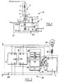
- the power system 10 represented in FIG. 1 comprises a load 2, for example of an inductive nature, which can be modeled for example by an inductor 3, a resistor 4 and a switch 5, and a switching device 1 comprising a power switch 6 of the type triac having a control trigger on which is applied a control signal C and an extraction device 100 according to the invention directly associated with the triac 6.
- This triac 6 is interposed between an alternating power supply having two poles N, P and the load 2 to which the triac 6 is connected by a charging terminal L.
- the load 2 can be of a more or less inductive nature depending on the importance of the inductive component 3 relative to the resistive component 4. This load 2 can be present (switch 5 closed) or absent (switch 5 open).
- An auxiliary power supply 13 delivers a DC voltage + V on a terminal connected to one of the poles P of the alternative power source and to the anode of the triac 6, the mass 0V of this auxiliary power supply being connected to the ground of the extraction device 100 according to the invention.
- a transistor 11, for example a PNP type bipolar transistor, preferably having good sensitivity and switching characteristics, ensures the shaping of an extracted signal so that it can be processed in the form of a logic signal S by a processing logic (not shown in Figure 1) which will be described later.
- signal shaping includes obtaining steep edges and a predetermined amplitude, for example equal to 5 volts.
- the extracted raw signal is taken across the triac 6 by the resistor 7 which forms with the resistor 8 a current divider bridge ensuring correct control of the transistor 11.
- the respective values of the resistors 7 and 8 must be chosen as a function of the characteristics of the transistor 11, according to conventional considerations of bias of a transistor. It is also possible, for a good quality transistor 11, to plan to remove the resistor 8, and to use only a resistor 7 placed between a first terminal of the triac 6 and the base of the transistor 11, the second terminal of the triac 6 is then connected to the emitter of transistor 11.
- the diode 9 ensures the clipping of negative voltages around the 0 Volt potential and thus protects transistor 11 against too large voltage excursions across the transistor.
- the extraction device according to the invention which has just been described can be implemented in a switching device 1 within a device 20 for managing an incandescent lighting source remotely controllable and capable of '' informing remote devices in the event of a filament break, the internal architecture of which is described by way of example in FIG. 2.
- the lighting management device 20 comprises a bulb 29 which constitutes the load and a control device 200 including switching device 1.
- the switching device is arranged between the load 29 and an alternative power source N, P to which are also connected an auxiliary power device 21 , a carrier current transmission device 22, a control and processing unit 23, for example a microcontroller, and a circuit 24 for generating a signal for controlling the triac on the basis of a logic signal emitted by the control and processing unit 23.
- the auxiliary supply device 21 is designed to deliver several levels of DC voltage, for example a voltage level of +5 volts and a voltage level of +10 volts, intended for the various components of the control device 200.
- the generator circuit 24 can conventionally comprise a transistor 33, for example a bipolar NPN transistor, a base resistance 32 connecting the base of the transistor 33 to a control output from the control and processing unit 23 and a collector resistor 31 connecting the collector of transistor 33 to the control input C of switching device 1, the emitter of transistor 33 being connected to ground of the control device 200.
- a transistor 33 for example a bipolar NPN transistor
- a base resistance 32 connecting the base of the transistor 33 to a control output from the control and processing unit 23
- a collector resistor 31 connecting the collector of transistor 33 to the control input C of switching device 1, the emitter of transistor 33 being connected to ground of the control device 200.
- the software modules D + and D- for end-of-travel detection are designed to receive and process output signals S ', S respectively from the switching devices 1', 1, while the software modules CT + and CT- for controlling triac are designed to generate control signals C ', C and apply them respectively to the switching devices 1', 1.
- the actuator is for example a single-phase asynchronous motor 34 having a first winding 45 and a second winding 44 having in common a first terminal connected via a thermal safety contact 43 to a pole N of the alternating supply.
- the respective second terminals of each winding 45, 44 are connected on the one hand, respectively via limit switches 46, 47 to the respective load terminals L ', L of the respective switching devices 1', 1 and on the other part, across a phase shift capacitor 35.
- a resistive element 37 and an inductive element 38 are conventionally inserted between the charge terminals L ′, L and the terminals of the phase shift capacitor 35, in order to protect the two triacs equipping the two switching devices 1 ', 1 in the event of accidental simultaneous ignition.
- Safety contact 43 such as a thermal contact or torque overrun etc, which is especially provided in the case of electric roller shutters, trips in the event of overheating caused by excessive use or in the event of mechanical blockage. It is easy to detect the passage in safety cut-off by the extraction process according to the invention and it should be noted that, for this application, this is the only case where a disappearance of charge is detected simultaneously in the two branches of power.
- the microcontroller is preferably programmed to identify the opening of the safety contact when it receives simultaneous no-load detection signals from all switching devices.
- the control device 30 makes it possible to remotely control, for example, a rolling shutter to which an opening or closing instruction can be transmitted between 0 and 100%. Learning the duration of the total movement between the two stops as well as periodic resetting are fully automated operations thanks to end-of-travel detection by disappearance of load during movement.
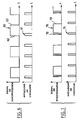
- the device according to the invention When a load is present, the device according to the invention generates a signal SP as shown by way of example in FIG. 4, which is not modified by a change in state of the switching device.
- the supply voltage is 230 volts rms with a frequency of 50 Hz and a duty cycle of 50%. It can be observed that the signal SP generated by the device according to the invention conforms in frequency and in cyclic relationship to the supply voltage. The amplitude of this signal is here equal to 5 volts so that it can be applied to a standard control device.
- the extraction method according to the invention can be easily implemented as a method for detecting the presence and absence of charge.
- only the situation of the presence of a load leads to the generation of a signal having frequency and duty cycle conditions close to those of the AC supply.
- the detection of presence and absence of charge amounts to discriminating an alternating signal from a signal at constant amplitude, which does not presents no difficulty with conventional methods of discrimination.
- a classic discrimination technique consists in comparing the duration of two consecutive half-waves which must be equal while respecting a certain tolerance to signify the presence of a charge. It is also possible to compare the duration of a half-wave with a fixed value corresponding to the characteristics of the supply voltage, for example 10 ms in the case of a 50 Hz network.
- the detection of the absence or the presence of a load at the terminals of an alternating current switching device such as a triac is obtained by using the fact that this type of pulse-controlled switch is only maintained in the closed state after disappearance of the control pulse if the current in the load exceeds a value characteristic of the switch model used.
- the synchronization signal is a square signal 60 of the same period as the supply voltage and of period twice that of the control pulses 61 which alternately coincide with the rising edges 62 and descendants 63 of the synchronization signal, as illustrated in FIG. 6.
- the control pulses bring the synchronization signal to the opposite logic state at least all the positive half-waves or all the negative half-waves.
- the half-cycle affected by this training effect depends of the technology of the switch used and of the polarity of the control pulse with respect to the reference electrode of the switch.
- one control pulse out of two leads to the generation of a very short pulse 72 on the synchronization signal 70, then a low logic state until the disappearance of the control pulse 71 , followed by a high logic state on the rest of the half-cycle concerned and a falling edge 73 synchronous with the next control pulse.
- a detection device capable of detecting the existence or not on the synchronization signal of this drive pulse indicative of the absence of a significant charge. More generally, the training pulses observed on a synchronization signal in the absence of charge constitute a detectable alteration of the waveform of this signal. One can also consider other forms of alteration detectable on the synchronization signal, for example having a polarity or a shape different from that which has just been described.
- the second method for detecting the presence / absence of charge implements a combined processing of the synchronization signal with the command pulse signal to detect the presence or the absence of charge.
- This second technique is preferred when the power of the loads to be controlled is greater than the holding current of the switch concerned, that is to say, when this switch can be controlled by pulse.
- This method offers the advantage of not being disturbed by the length of the cables separating the switch from the controlled load, of being able to detect an absence of load at the secondary of a transformer while the primary is still connected in the switch circuit, and to be simple to implement.
- the first detection method in the framework of the method according to the invention, which is based on the detection of a synchronization waveform different from a square signal at the sector frequency.
- the invention can be applied to switching devices other than a triac. It is also possible to use components for shaping the extracted signal other than a bipolar PNP transistor. Likewise, many other protection devices can be envisaged than a silicon diode.
- the method according to the invention in the context of applications related to energy management, in particular in combination with a method of managing electrical power in a home automation network as disclosed in French patent application No. 9112604 in the name of the present applicant.
- the method according to the invention can also be associated with methods for managing the pricing of electrical energy and with methods of analytical energy metering.
- the association of the method according to the invention with these energy management methods makes it possible to provide not only the synchronization information necessary to ensure the switching of the power loads under good conditions but also information detection of presence or absence of a charge.
- the control of the presence of the load makes it possible to envisage the implementation of energy management methods in devices "tracking" the state of an external load for which it is no longer necessary to have a direct contact with the user. It is thus possible to produce adaptations of existing products which do not require a change in usage habits while offering the benefits of the implementation of the management processes concerned.
Landscapes
- Remote Monitoring And Control Of Power-Distribution Networks (AREA)
Applications Claiming Priority (2)
| Application Number | Priority Date | Filing Date | Title |
|---|---|---|---|
| FR9314743A FR2713844B1 (fr) | 1993-12-08 | 1993-12-08 | Procédé et dispositif pour extraire un signal indicatif de l'état de charge d'un commutateur de puissance, et dispositifs de commutation et de commande associés. |
| FR9314743 | 1993-12-08 |
Publications (1)
| Publication Number | Publication Date |
|---|---|
| EP0658002A1 true EP0658002A1 (de) | 1995-06-14 |
Family
ID=9453710
Family Applications (1)
| Application Number | Title | Priority Date | Filing Date |
|---|---|---|---|
| EP94402790A Withdrawn EP0658002A1 (de) | 1993-12-08 | 1994-12-06 | Verfahren und Vorrichtung zum Herauslösen eines den Belastungszustand eines Leistungschaltersanzeigenden Signals, und entsprechende Schalt- und Steuervorrichtungen |
Country Status (2)
| Country | Link |
|---|---|
| EP (1) | EP0658002A1 (de) |
| FR (1) | FR2713844B1 (de) |
Citations (4)
| Publication number | Priority date | Publication date | Assignee | Title |
|---|---|---|---|---|
| EP0163332A1 (de) * | 1984-05-11 | 1985-12-04 | Philips Composants | Statisches Relais für Gleichstrom |
| DE3928225A1 (de) * | 1988-08-30 | 1990-03-08 | Alps Electric Co Ltd | Lastzustandsdetektor- und lasttreibersystem |
| EP0374417A2 (de) * | 1988-12-20 | 1990-06-27 | Albert Walter Duin | Schutzvorrichtung für elektrische Geräte |
| EP0608477A2 (de) * | 1993-01-26 | 1994-08-03 | Carlo Gavazzi AG | Halbleiterrelais |
-
1993
- 1993-12-08 FR FR9314743A patent/FR2713844B1/fr not_active Expired - Fee Related
-
1994
- 1994-12-06 EP EP94402790A patent/EP0658002A1/de not_active Withdrawn
Patent Citations (4)
| Publication number | Priority date | Publication date | Assignee | Title |
|---|---|---|---|---|
| EP0163332A1 (de) * | 1984-05-11 | 1985-12-04 | Philips Composants | Statisches Relais für Gleichstrom |
| DE3928225A1 (de) * | 1988-08-30 | 1990-03-08 | Alps Electric Co Ltd | Lastzustandsdetektor- und lasttreibersystem |
| EP0374417A2 (de) * | 1988-12-20 | 1990-06-27 | Albert Walter Duin | Schutzvorrichtung für elektrische Geräte |
| EP0608477A2 (de) * | 1993-01-26 | 1994-08-03 | Carlo Gavazzi AG | Halbleiterrelais |
Also Published As
| Publication number | Publication date |
|---|---|
| FR2713844B1 (fr) | 1996-02-23 |
| FR2713844A1 (fr) | 1995-06-16 |
Similar Documents
| Publication | Publication Date | Title |
|---|---|---|
| CH624250A5 (de) | ||
| EP0448434B1 (de) | Gleichrichter für mindestens zwei Versorgungswechselspannungsbereiche | |
| FR2478896A1 (fr) | Moteur a courant continu sans collecteur | |
| FR2556899A1 (fr) | Procede et appareil pour commander la moyenne des demi-alternances ou la moyenne quadratique de la tension d'une charge | |
| FR2596927A1 (fr) | Circuit de protection d'alimentation a decoupage | |
| FR2871627A1 (fr) | Relais a l'etat solide pour la commutation d'une alimentation en alternatif vers une charge reactive et procede pour faire fonctionner un tel relais | |
| CH621895A5 (de) | ||
| EP0836280B1 (de) | Elektronischer Schalter mit Zweidraht-Versorgung | |
| EP0394110B1 (de) | Schaltsteuerverfahren für eine Vollwellenleistungsversorgung einer dreiphasigen Schaltung | |
| FR2502412A1 (fr) | Perfectionnements aux disjoncteurs sensibles aux courants de fuite | |
| EP0658002A1 (de) | Verfahren und Vorrichtung zum Herauslösen eines den Belastungszustand eines Leistungschaltersanzeigenden Signals, und entsprechende Schalt- und Steuervorrichtungen | |
| FR2532487A1 (fr) | Regulateur pour charge de batterie d'accumulateurs par alternateur a aimant permanent | |
| EP1540845A1 (de) | Verfahren zur steuerung der aktivierung eines elektromechanischen betätigungsgliedes | |
| EP1061650A1 (de) | Bistabiler Zweirichtungs-Hochspannungsschalter | |
| FR2662869A1 (fr) | Procede de limitation d'une surcharge base sur la technique de controle pwm (ou lc3) et dispositif electronique de mise en óoeuvre de ce procede. | |
| EP0110481A1 (de) | System zur Identifizierung lokaler Stationen durch eine zentrale Abfragestation | |
| EP3461236B1 (de) | Verfahren zur inbetriebnahme einer einheit aus mindestens zwei dimmern | |
| EP0297957A1 (de) | Steuer- und Kontrollvorrichtung für Schütze und entsprechendes Kontrollverfahren | |
| EP0037763B1 (de) | Fernsteuerungsvorrichtung für an eine Wechselstromversorgungsanlage angeschlossene Heizungsapparate | |
| EP3121366B1 (de) | Verfahren zur erkennung der bewegungsrichtung einer verdunkelungsblende | |
| FR2759512A1 (fr) | Procede et dispositif de telesurveillance de postes de drainage, ou de drainage de courants telesurveille, fonctionnant sur ouvrage metallique soumis a l'influence de courants vagabons | |
| EP2634900B1 (de) | Zweipolige Dimmerschaltung | |
| EP1414144B1 (de) | Verfahren und Vorrichtung zur Mittelleistungssteuerung einer Wechselstromlast | |
| EP0196934B1 (de) | Steuerschaltung für Taktversorgung für verschiedene Anwendungen | |
| EP0707371B1 (de) | Vorrichtung und Verfahren zur Übertragung von digitalen Daten über einen Bus |
Legal Events
| Date | Code | Title | Description |
|---|---|---|---|
| PUAI | Public reference made under article 153(3) epc to a published international application that has entered the european phase |
Free format text: ORIGINAL CODE: 0009012 |
|
| 17P | Request for examination filed |
Effective date: 19950209 |
|
| AK | Designated contracting states |
Kind code of ref document: A1 Designated state(s): CH DE ES FR GB IT LI NL |
|
| 17Q | First examination report despatched |
Effective date: 19970227 |
|
| GRAG | Despatch of communication of intention to grant |
Free format text: ORIGINAL CODE: EPIDOS AGRA |
|
| GRAG | Despatch of communication of intention to grant |
Free format text: ORIGINAL CODE: EPIDOS AGRA |
|
| GRAH | Despatch of communication of intention to grant a patent |
Free format text: ORIGINAL CODE: EPIDOS IGRA |
|
| RAP1 | Party data changed (applicant data changed or rights of an application transferred) |
Owner name: EURO CP S.A.R.L. |
|
| STAA | Information on the status of an ep patent application or granted ep patent |
Free format text: STATUS: THE APPLICATION IS DEEMED TO BE WITHDRAWN |
|
| 18D | Application deemed to be withdrawn |
Effective date: 19980627 |