EP0658059A1 - Plaque à bornes de raccordement et déconnexion - Google Patents
Plaque à bornes de raccordement et déconnexion Download PDFInfo
- Publication number
- EP0658059A1 EP0658059A1 EP94117494A EP94117494A EP0658059A1 EP 0658059 A1 EP0658059 A1 EP 0658059A1 EP 94117494 A EP94117494 A EP 94117494A EP 94117494 A EP94117494 A EP 94117494A EP 0658059 A1 EP0658059 A1 EP 0658059A1
- Authority
- EP
- European Patent Office
- Prior art keywords
- contacting
- connection part
- earth connection
- outgoing
- conductors
- Prior art date
- Legal status (The legal status is an assumption and is not a legal conclusion. Google has not performed a legal analysis and makes no representation as to the accuracy of the status listed.)
- Granted
Links
- 239000004020 conductor Substances 0.000 abstract description 13
- 239000000945 filler Substances 0.000 abstract 1
- 238000006073 displacement reaction Methods 0.000 description 4
- 238000009413 insulation Methods 0.000 description 4
- 210000002105 tongue Anatomy 0.000 description 2
- 238000010276 construction Methods 0.000 description 1
- 230000005684 electric field Effects 0.000 description 1
- 239000002184 metal Substances 0.000 description 1
Images
Classifications
-
- H—ELECTRICITY
- H01—ELECTRIC ELEMENTS
- H01R—ELECTRICALLY-CONDUCTIVE CONNECTIONS; STRUCTURAL ASSOCIATIONS OF A PLURALITY OF MUTUALLY-INSULATED ELECTRICAL CONNECTING ELEMENTS; COUPLING DEVICES; CURRENT COLLECTORS
- H01R13/00—Details of coupling devices of the kinds covered by groups H01R12/70 or H01R24/00 - H01R33/00
- H01R13/648—Protective earth or shield arrangements on coupling devices, e.g. anti-static shielding
- H01R13/658—High frequency shielding arrangements, e.g. against EMI [Electro-Magnetic Interference] or EMP [Electro-Magnetic Pulse]
- H01R13/6581—Shield structure
- H01R13/6582—Shield structure with resilient means for engaging mating connector
- H01R13/6583—Shield structure with resilient means for engaging mating connector with separate conductive resilient members between mating shield members
-
- H—ELECTRICITY
- H01—ELECTRIC ELEMENTS
- H01R—ELECTRICALLY-CONDUCTIVE CONNECTIONS; STRUCTURAL ASSOCIATIONS OF A PLURALITY OF MUTUALLY-INSULATED ELECTRICAL CONNECTING ELEMENTS; COUPLING DEVICES; CURRENT COLLECTORS
- H01R13/00—Details of coupling devices of the kinds covered by groups H01R12/70 or H01R24/00 - H01R33/00
- H01R13/648—Protective earth or shield arrangements on coupling devices, e.g. anti-static shielding
- H01R13/658—High frequency shielding arrangements, e.g. against EMI [Electro-Magnetic Interference] or EMP [Electro-Magnetic Pulse]
- H01R13/6591—Specific features or arrangements of connection of shield to conductive members
- H01R13/6592—Specific features or arrangements of connection of shield to conductive members the conductive member being a shielded cable
- H01R13/6593—Specific features or arrangements of connection of shield to conductive members the conductive member being a shielded cable the shield being composed of different pieces
-
- H—ELECTRICITY
- H01—ELECTRIC ELEMENTS
- H01R—ELECTRICALLY-CONDUCTIVE CONNECTIONS; STRUCTURAL ASSOCIATIONS OF A PLURALITY OF MUTUALLY-INSULATED ELECTRICAL CONNECTING ELEMENTS; COUPLING DEVICES; CURRENT COLLECTORS
- H01R13/00—Details of coupling devices of the kinds covered by groups H01R12/70 or H01R24/00 - H01R33/00
- H01R13/648—Protective earth or shield arrangements on coupling devices, e.g. anti-static shielding
- H01R13/658—High frequency shielding arrangements, e.g. against EMI [Electro-Magnetic Interference] or EMP [Electro-Magnetic Pulse]
- H01R13/6591—Specific features or arrangements of connection of shield to conductive members
- H01R13/6596—Specific features or arrangements of connection of shield to conductive members the conductive member being a metal grounding panel
-
- H—ELECTRICITY
- H04—ELECTRIC COMMUNICATION TECHNIQUE
- H04Q—SELECTING
- H04Q1/00—Details of selecting apparatus or arrangements
- H04Q1/02—Constructional details
- H04Q1/14—Distribution frames
- H04Q1/142—Terminal blocks for distribution frames
-
- H—ELECTRICITY
- H04—ELECTRIC COMMUNICATION TECHNIQUE
- H04Q—SELECTING
- H04Q2201/00—Constructional details of selecting arrangements
- H04Q2201/14—Screening, grounding or crosstalk reduction details
-
- H—ELECTRICITY
- H04—ELECTRIC COMMUNICATION TECHNIQUE
- H04Q—SELECTING
- H04Q2201/00—Constructional details of selecting arrangements
- H04Q2201/18—Rails
Definitions
- the present invention relates to a connecting and disconnecting strip for distributing a plurality of conductors of shielded cables for tele and data communication, with first means for insulation displacement connection of the incoming conductors and second means for insulation displacement connection of the outgoing conductors or overpasses , wherein the bar can be installed in a support frame and the shielding of the cables can be connected to the mass of the support frame.
- the object of the present invention is therefore to provide a connection and isolating strip of the aforementioned type, in which an optimal grounding of the shielding of the cables, respectively.
- Conductor can be manufactured under RF conditions.
- a first earth connection part which can be plugged into the strip and has a protrusion for supporting, fastening and contacting the shielding of the incoming cable, with spring means for contacting the support frame, with multiple protrusions for contacting the side wires and with clamping means for clamping, contacting plugging on a second earth connection part for receiving and shielding contacting of the outgoing shielded cable.
- first earth connection part is approximately T-shaped, the multiple projections projecting like a comb from the crosspiece of the earth connection part and the clamping means for the second earth connection part are bent laterally on the other web.
- the second earth connection part is advantageously box-shaped with a first inner subdivision for the lateral lead-out of the shielded outgoing cables and with spring tongues for contacting the shields of the outgoing cables and with a second inner subdivision for leading out the isolated outgoing conductors or overpasses.
- the second box-shaped earth connection part can have a lateral protrusion which extends with surface parts between the webs of the clamping means of the first earth connection part.
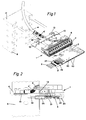
- connection and disconnection strip comprises, in a known manner, first means 6 for insulation displacement connection of the incoming conductors 2 and second means 7 for insulation displacement connection of the outgoing conductors or transfers 3, the strip 1 can be installed in a support frame 8 and the shield 4 ', 5' of the cable 4, 5 can be connected to the mass of the support frame.
- a first earth connection part 10 which can be plugged into the strip 1, is now provided with a protrusion 11 for supporting, fastening and contacting the shield 4 'of the incoming cable 4, and with spring means 12 for contacting the support frame 8, with multiple protrusions 13 for contacting of drainage wires and clamping means 14 for clamping, contacting attachment of a second earth connection part 20.
- This second earth connection part serves for receiving and shielding contacting of the outgoing shielded cables 5.
- the first earth connection part 10 is approximately T-shaped, the multiple protrusions 13 from Project the crosspiece of the earth connection part like a comb and the clamping means 14 for the second earth connection part 20 on the other web are bent laterally.
- the second earth connection part 20 is box-shaped with a first inner subdivision 21 for the lateral leading out of the shielded outgoing cables 5 and with spring tongues 22 for contacting the shields 5 'of the outgoing cables 5. Furthermore, the box-like part 20 has a second inner subdivision 23 for leading out the isolated outgoing ladder or overpasses 3. Furthermore, there is a lateral protrusion 24 on the second box-shaped earth connection part 20, which extends with surface parts between the webs of the clamping means 14 of the first earth connection part 10.
- the earth connection parts 10 and 20 can be made of any suitable conductive metal.
Landscapes
- Engineering & Computer Science (AREA)
- Computer Networks & Wireless Communication (AREA)
- Cable Accessories (AREA)
Applications Claiming Priority (3)
| Application Number | Priority Date | Filing Date | Title |
|---|---|---|---|
| CH3412/93 | 1993-11-15 | ||
| CH341293 | 1993-11-15 | ||
| CH341293A CH689606A5 (de) | 1993-11-15 | 1993-11-15 | Vorrichtung zum Trennverteilen einer Vielzahl Leiter von abgeschirmten Kabeln. |
Publications (2)
| Publication Number | Publication Date |
|---|---|
| EP0658059A1 true EP0658059A1 (fr) | 1995-06-14 |
| EP0658059B1 EP0658059B1 (fr) | 1999-07-28 |
Family
ID=4255433
Family Applications (1)
| Application Number | Title | Priority Date | Filing Date |
|---|---|---|---|
| EP19940117494 Expired - Lifetime EP0658059B1 (fr) | 1993-11-15 | 1994-11-07 | Plaque à bornes de raccordement et déconnexion |
Country Status (3)
| Country | Link |
|---|---|
| EP (1) | EP0658059B1 (fr) |
| CH (1) | CH689606A5 (fr) |
| DE (1) | DE59408544D1 (fr) |
Cited By (8)
| Publication number | Priority date | Publication date | Assignee | Title |
|---|---|---|---|---|
| FR2758660A1 (fr) * | 1997-01-23 | 1998-07-24 | Alsthom Cge Alcatel | Panneau modulaire de brassage, pour reseaux de donnees |
| EP0778711A3 (fr) * | 1995-12-07 | 1999-01-07 | Btr Blumberger Telefon- Und Relaisbau Albert Metz | Tableau de connexions, en particulier pour réseaux de transmission de données |
| EP0905822A1 (fr) * | 1997-09-29 | 1999-03-31 | Siemens Aktiengesellschaft | Connecteur pour câbles avec contact de mise à la masse |
| DE10001553A1 (de) * | 2000-01-14 | 2001-08-02 | Krone Gmbh | Vorrichtung zur Schirmung für Anschlussleisten |
| WO2003089047A1 (fr) * | 2002-04-19 | 2003-10-30 | Medtronic, Inc. | Cable multiport de depistage neurologique |
| EP1005235A3 (fr) * | 1998-11-25 | 2004-03-17 | Reichle & De-Massari AG | Dispositif pour fixer des blocs de connexion modulaires multiples à des éléments porteurs parallèles d'un répartiteur d'un central téléphonique ou analogue |
| DE10245939A1 (de) * | 2002-09-30 | 2004-05-27 | Siemens Ag | Vorrichtung zur Energieversorgung eines Gerätes |
| WO2007090489A1 (fr) * | 2006-02-08 | 2007-08-16 | Ccs Technology, Inc. | Dispositif de blindage pour blocs de distribution |
Citations (4)
| Publication number | Priority date | Publication date | Assignee | Title |
|---|---|---|---|---|
| DE2348466B2 (de) * | 1973-09-26 | 1977-11-03 | Siemens AG, 1000 Berlin und 8000 München | Verdrahtungsanordnung fuer gestelle der elektrischen nachrichten-, insbesondere fernsprechvermittlungstechnik |
| DE2643046B2 (de) * | 1976-09-24 | 1978-10-12 | Siemens Ag, 1000 Berlin Und 8000 Muenchen | Zwischenverteiler für Fernmeldevermittlungsanlagen |
| EP0402658A2 (fr) * | 1989-06-15 | 1990-12-19 | Siemens Aktiengesellschaft | Bloc de raccordement pour lignes électriques entrantes et sortantes |
| EP0455274A2 (fr) * | 1985-03-16 | 1991-11-06 | Quante Aktiengesellschaft | Unité de connection de câbles |
-
1993
- 1993-11-15 CH CH341293A patent/CH689606A5/de not_active IP Right Cessation
-
1994
- 1994-11-07 DE DE59408544T patent/DE59408544D1/de not_active Expired - Fee Related
- 1994-11-07 EP EP19940117494 patent/EP0658059B1/fr not_active Expired - Lifetime
Patent Citations (4)
| Publication number | Priority date | Publication date | Assignee | Title |
|---|---|---|---|---|
| DE2348466B2 (de) * | 1973-09-26 | 1977-11-03 | Siemens AG, 1000 Berlin und 8000 München | Verdrahtungsanordnung fuer gestelle der elektrischen nachrichten-, insbesondere fernsprechvermittlungstechnik |
| DE2643046B2 (de) * | 1976-09-24 | 1978-10-12 | Siemens Ag, 1000 Berlin Und 8000 Muenchen | Zwischenverteiler für Fernmeldevermittlungsanlagen |
| EP0455274A2 (fr) * | 1985-03-16 | 1991-11-06 | Quante Aktiengesellschaft | Unité de connection de câbles |
| EP0402658A2 (fr) * | 1989-06-15 | 1990-12-19 | Siemens Aktiengesellschaft | Bloc de raccordement pour lignes électriques entrantes et sortantes |
Cited By (12)
| Publication number | Priority date | Publication date | Assignee | Title |
|---|---|---|---|---|
| EP0778711A3 (fr) * | 1995-12-07 | 1999-01-07 | Btr Blumberger Telefon- Und Relaisbau Albert Metz | Tableau de connexions, en particulier pour réseaux de transmission de données |
| FR2758660A1 (fr) * | 1997-01-23 | 1998-07-24 | Alsthom Cge Alcatel | Panneau modulaire de brassage, pour reseaux de donnees |
| EP0859526A1 (fr) * | 1997-01-23 | 1998-08-19 | Alcatel | Panneau modulaire de brassage, pour réseaux de données |
| US6077113A (en) * | 1997-01-23 | 2000-06-20 | Alcatel | Modular cross-connect panel for data networks |
| EP0905822A1 (fr) * | 1997-09-29 | 1999-03-31 | Siemens Aktiengesellschaft | Connecteur pour câbles avec contact de mise à la masse |
| EP1005235A3 (fr) * | 1998-11-25 | 2004-03-17 | Reichle & De-Massari AG | Dispositif pour fixer des blocs de connexion modulaires multiples à des éléments porteurs parallèles d'un répartiteur d'un central téléphonique ou analogue |
| DE10001553A1 (de) * | 2000-01-14 | 2001-08-02 | Krone Gmbh | Vorrichtung zur Schirmung für Anschlussleisten |
| EP1117158A3 (fr) * | 2000-01-14 | 2002-06-12 | KRONE GmbH | Dispositif de blindage de fixation d'élements de raccordement |
| WO2003089047A1 (fr) * | 2002-04-19 | 2003-10-30 | Medtronic, Inc. | Cable multiport de depistage neurologique |
| DE10245939A1 (de) * | 2002-09-30 | 2004-05-27 | Siemens Ag | Vorrichtung zur Energieversorgung eines Gerätes |
| EP1403969B1 (fr) * | 2002-09-30 | 2016-08-17 | Siemens Aktiengesellschaft | Dispoditif d'alimentation de puissance pour un appareil |
| WO2007090489A1 (fr) * | 2006-02-08 | 2007-08-16 | Ccs Technology, Inc. | Dispositif de blindage pour blocs de distribution |
Also Published As
| Publication number | Publication date |
|---|---|
| EP0658059B1 (fr) | 1999-07-28 |
| DE59408544D1 (de) | 1999-09-02 |
| CH689606A5 (de) | 1999-06-30 |
Similar Documents
| Publication | Publication Date | Title |
|---|---|---|
| EP0847106B1 (fr) | Bornier électrique, plaque à bornes de raccordement ou déconnexion | |
| DE19959823C2 (de) | Verbindungskabel mit elektrischer Steckverbindung | |
| DE10339844B3 (de) | Verteileranschlussmodul | |
| EP0586841A1 (fr) | Circuit imprimé et module de montage pour connexion d'un câble blindé et système répartiteur pour construction d'un dispositif basse-tension | |
| EP0388585A2 (fr) | Connecteur de protection pour barrette de connexion pour technique de télécommunication et de traitement de données | |
| EP0766482A2 (fr) | Dispositif de distribution pour la technique de télécommuication et de données | |
| DE19617114C2 (de) | Erdungsmodul | |
| EP0658059B1 (fr) | Plaque à bornes de raccordement et déconnexion | |
| EP0529267B1 (fr) | Bloc de connexion pour technique des télécommunications et des données | |
| DE102007032577B4 (de) | Endverschluss für die Telekommunikations- und Datentechnik | |
| EP1005235A2 (fr) | Dispositif pour fixer des blocs de connexion modulaires multiples à des éléments porteurs parallèles d'un répartiteur d'un central téléphonique ou analogue | |
| DE29519389U1 (de) | Steckverteiler, insbesondere für Datenübertragungsnetze | |
| DE9202912U1 (de) | Elektrische Buchsen aufweisender Frontabschluß für elektrische Schränke, Gehäuse, Gestelle od. dgl. | |
| DE19537529C1 (de) | Verteilerleiste für die Telekommunikations- und Datentechnik | |
| EP0671787B1 (fr) | Dispositif pour la connexion de conducteurs blindés dans la téléphonie et communication de données | |
| EP0660458B1 (fr) | Dispositifs de raccordement pour lignes de télécommunications / données | |
| DE10357468B4 (de) | Rangier- oder Geräteverbindungsleitung für Kommunikationsanlagen zum Einsatz in Netzwerken | |
| DE19734422C2 (de) | Patchpanel | |
| DE29920712U1 (de) | Systemseitiges Anschlussmodul und Verteiler der Telekommunikationstechnik | |
| EP0071264A2 (fr) | Bloc de raccordement pour centraux téléphoniques | |
| DE29515983U1 (de) | Montagebügel | |
| DE9407225U1 (de) | Stecker für die Telekommunikations- und Datentechnik | |
| DE29807669U1 (de) | Montagewanne für einen Endverschluß | |
| DE29519388U1 (de) | Steckverteiler, insbesondere Telefonverteiler | |
| DE4302876A1 (de) | Frontabschluß für elektrische Schränke, Gehäuse, Gestelle oder dergleichen |
Legal Events
| Date | Code | Title | Description |
|---|---|---|---|
| PUAI | Public reference made under article 153(3) epc to a published international application that has entered the european phase |
Free format text: ORIGINAL CODE: 0009012 |
|
| AK | Designated contracting states |
Kind code of ref document: A1 Designated state(s): DE FR GB IT |
|
| 17P | Request for examination filed |
Effective date: 19951123 |
|
| GRAG | Despatch of communication of intention to grant |
Free format text: ORIGINAL CODE: EPIDOS AGRA |
|
| GRAG | Despatch of communication of intention to grant |
Free format text: ORIGINAL CODE: EPIDOS AGRA |
|
| GRAH | Despatch of communication of intention to grant a patent |
Free format text: ORIGINAL CODE: EPIDOS IGRA |
|
| 17Q | First examination report despatched |
Effective date: 19990112 |
|
| GRAH | Despatch of communication of intention to grant a patent |
Free format text: ORIGINAL CODE: EPIDOS IGRA |
|
| GRAA | (expected) grant |
Free format text: ORIGINAL CODE: 0009210 |
|
| AK | Designated contracting states |
Kind code of ref document: B1 Designated state(s): DE FR GB IT |
|
| PG25 | Lapsed in a contracting state [announced via postgrant information from national office to epo] |
Ref country code: IT Free format text: LAPSE BECAUSE OF FAILURE TO SUBMIT A TRANSLATION OF THE DESCRIPTION OR TO PAY THE FEE WITHIN THE PRE;WARNING: LAPSES OF ITALIAN PATENTS WITH EFFECTIVE DATE BEFORE 2007 MAY HAVE OCCURRED AT ANY TIME BEFORE 2007. THE CORRECT EFFECTIVE DATE MAY BE DIFFERENT FROM THE ONE RECORDED.SCRIBED TIME-LIMIT Effective date: 19990728 Ref country code: GB Free format text: LAPSE BECAUSE OF FAILURE TO SUBMIT A TRANSLATION OF THE DESCRIPTION OR TO PAY THE FEE WITHIN THE PRESCRIBED TIME-LIMIT Effective date: 19990728 Ref country code: FR Free format text: LAPSE BECAUSE OF FAILURE TO SUBMIT A TRANSLATION OF THE DESCRIPTION OR TO PAY THE FEE WITHIN THE PRESCRIBED TIME-LIMIT Effective date: 19990728 |
|
| REF | Corresponds to: |
Ref document number: 59408544 Country of ref document: DE Date of ref document: 19990902 |
|
| EN | Fr: translation not filed | ||
| GBV | Gb: ep patent (uk) treated as always having been void in accordance with gb section 77(7)/1977 [no translation filed] |
Effective date: 19990728 |
|
| PLBE | No opposition filed within time limit |
Free format text: ORIGINAL CODE: 0009261 |
|
| STAA | Information on the status of an ep patent application or granted ep patent |
Free format text: STATUS: NO OPPOSITION FILED WITHIN TIME LIMIT |
|
| 26N | No opposition filed | ||
| PGFP | Annual fee paid to national office [announced via postgrant information from national office to epo] |
Ref country code: DE Payment date: 20051227 Year of fee payment: 12 |
|
| PG25 | Lapsed in a contracting state [announced via postgrant information from national office to epo] |
Ref country code: DE Free format text: LAPSE BECAUSE OF NON-PAYMENT OF DUE FEES Effective date: 20070601 |