EP0658064A2 - Tonwiedergabegerät - Google Patents
Tonwiedergabegerät Download PDFInfo
- Publication number
- EP0658064A2 EP0658064A2 EP94119350A EP94119350A EP0658064A2 EP 0658064 A2 EP0658064 A2 EP 0658064A2 EP 94119350 A EP94119350 A EP 94119350A EP 94119350 A EP94119350 A EP 94119350A EP 0658064 A2 EP0658064 A2 EP 0658064A2
- Authority
- EP
- European Patent Office
- Prior art keywords
- subtractor
- microphone
- output signal
- acoustic
- speaker
- Prior art date
- Legal status (The legal status is an assumption and is not a legal conclusion. Google has not performed a legal analysis and makes no representation as to the accuracy of the status listed.)
- Withdrawn
Links
Images


Classifications
-
- H—ELECTRICITY
- H04—ELECTRIC COMMUNICATION TECHNIQUE
- H04R—LOUDSPEAKERS, MICROPHONES, GRAMOPHONE PICK-UPS OR LIKE ACOUSTIC ELECTROMECHANICAL TRANSDUCERS; ELECTRIC HEARING AIDS; PUBLIC ADDRESS SYSTEMS
- H04R3/00—Circuits for transducers
- H04R3/002—Damping circuit arrangements for transducers, e.g. motional feedback circuits
Definitions
- the present invention relates to an acoustic reproducing apparatus for a reproduced sound from a speaker used in various acoustic appliances by a microphone, feeding back negatively to the input signal to the speaker by this detected signal to improve the reproduction frequency characteristic, distortion factor and other characteristics of the speaker, and correcting the reproduced sound.
- an acoustic reproducing apparatus in order to improve a reproduced sound from a speaker, it has been attempted to detect the reproduced sound by a microphone, feed back negatively to the input signal of the speaker by this detected signal to improve the reproduction frequency characteristic, distortion factor and other characteristics of the speaker, and correct the reproduced sound.
- a prior example of this kind of acoustic reproducing apparatus is described below by reference to drawings.
- Fig. 57 is a block diagram showing a constitution of an acoustic reproducing apparatus using a negative feedback circuit of a prior art.
- a signal is fed from an input terminal 50, and is supplied from a positive input terminal of a subtractor 51, and its output is amplified in power in a power amplifier 52, and the signal is applied to a speaker 53.
- the acoustic signal issued from the speaker 53 is detected by a microphone 54, and this signal is amplified in a microphone amplifier 55, and its output signal is passed through a filter 56 and is connected to a negative input terminal of the subtractor 51, thereby forming a negative feedback loop.
- Fig. 58 is a block diagram showing a constitution in which the speaker 53 of the acoustic reproducing apparatus shown in Fig. 57 is incorporated into a speaker box 58 using a passive radiator 57, wherein a signal fed into the input terminal 50 is passed into the subtractor 51 thorough the positive input terminal, and is amplified in power in the power amplifier 52, and the output signal from the power amplifier 52 is reproduced by the speaker 53 coupled inside the speaker box 58.
- an enclosed acoustic space 58A is formed, and further an enclosed acoustic space 58B is also formed at the front side of the speaker 53, and by the passive radiator 57 coupled between the enclosed acoustic space 58B and the opening of the speaker box 58, an acoustic output is radiated into the front space of the speaker box 58, and the acoustic output signal radiated from the passive radiator 57 is detected by the microphone 54, this detected signal is amplified by the microphone amplifier 55, and its output signal is passed through a filter 56 and connected to the negative input terminal of the subtractor 51, thereby forming a negative feedback loop.
- the phase difference between the electric signal entering the speaker 53 and the acoustic signal radiated from the passive radiator 57 varies significantly from +180 degrees to -180 degrees, and stable negative feedback is not obtained, and same as in the case of Fig. 57, further, the microphone 54 detects also the acoustic signal incoming noise aside from the acoustic signal radiated from the passive radiator 57, and a sufficient signal-to-noise ratio (S/N ratio) cannot be maintained, and if attempted to keep the S/N ratio by removing high frequency components by passing through the filter 56 or the like, a sufficient S/N ratio could not be attained.
- S/N ratio signal-to-noise ratio
- the invention is intended to solve these conventional problems and present an acoustic reproducing apparatus capable of improving the performance stably.
- a basic constitution of the acoustic reproducing apparatus of the invention comprises a subtractor connected to an input terminal, a power amplifier for amplifying the output signal of the subtractor, a speaker for reproducing the output signal of the power amplifier, a microphone for detecting the acoustic output signal radiated from the speaker, a microphone amplifier for amplifying the acoustic output signal detected by the microphone, and an adder/subtractor for adding or subtracting the output signal of the microphone amplifier and the input or output signal of the power amplifier, wherein the output signal of the adder/subtractor is connected to the subtractor to compose a negative feedback circuit.
- a filter may be inserted between the output of microphone amplifier and adder/subtractor, the output of microphone amplifier or filter is divided into two and added to two adders/subtractors, or it is also possible to modify to insert a high pass filter only in one of them, or to modify to connect another subtractor to the output of the subtractor connected to the input terminal, or it is possible to compose by further combining this modified circuit.
- the installation place of the microphone may have various positions around the speaker, and it may be determined according to the required detection characteristic.
- a microphone is disposed in an enclosed acoustic space at the front side of the magnetic circuit of the speaker for reproducing the output signal of the power amplifier or at the rear side of the speaker, or in an enclosed space between the speaker front side and passive radiator, and the output signal of the microphone is fed into the adder/subtractor to be added or subtracted with the input signal or the output signal of the power amplifier, and the signal is subtracted from the input terminal in the subtractor to compose a negative feedback circuit.
- the output of the microphone amplifier may be divided into two, and it may be modified same as the modifications of the basic constitution above.
- a phase shift circuit is added, or other modifications may be possible.
- the addition and subtraction method of the outputs may be also varied, and these modifications can be combined.
- the invention performs negative feedback by adding or subtracting the phase difference of the electric signal entered in the speaker and the acoustic output signal radiated from the speaker in the adder/subtractor, making it hard to cause oscillation (howling) due to positive feedback due to phase shifts and is hence capable of applying a negative feedback over a wide frequency range, powerfully and stably.
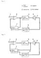
- Fig. 1 is a block diagram showing an acoustic reproducing apparatus according to embodiment 1 of the invention.
- Fig. 2 is a block diagram showing an acoustic reproducing apparatus according to embodiment 2 of the invention.
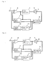
- Fig. 3 is a block diagram showing an acoustic reproducing apparatus according to embodiment 3 of the invention.
- Fig. 4 is a block diagram showing an acoustic reproducing apparatus according to embodiment 4 of the invention.
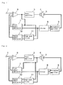
- Fig. 5 is a block diagram showing an acoustic reproducing apparatus according to embodiment 5 of the invention.
- Fig. 6 is a block diagram showing an acoustic reproducing apparatus according to embodiment 6 of the invention.
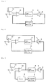
- Fig. 7 is a block diagram showing an acoustic reproducing apparatus according to embodiment 7 of the invention.
- Fig. 8 is a block diagram showing an acoustic reproducing apparatus according to embodiment 8 of the invention.
- Fig. 9 is a block diagram showing an acoustic reproducing apparatus according to embodiment 9 of the invention.
- Fig. 10 is a block diagram showing an acoustic reproducing apparatus according to embodiment 10 of the invention.
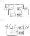
- Fig. 11 is a block diagram showing an acoustic reproducing apparatus according to embodiment 11 of the invention.
- Fig. 12 is a block diagram showing an acoustic reproducing apparatus according to embodiment 12 of the invention.
- Fig. 13 is a block diagram showing an acoustic reproducing apparatus according to embodiment 13 of the invention.
- Fig. 14 is a block diagram showing an acoustic reproducing apparatus according to embodiment 14 of the invention.
- Fig. 15 is a block diagram showing an acoustic reproducing apparatus according to embodiment 15 of the invention.
- Fig. 16 is a block diagram showing an acoustic reproducing apparatus according to embodiment 16 of the invention.
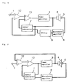
- Fig. 17 is a block diagram showing an acoustic reproducing apparatus according to embodiment 17 of the invention.
- Fig. 18 is a block diagram showing an acoustic reproducing apparatus according to embodiment 18 of the invention.
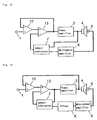
- Fig. 19 is a block diagram showing an acoustic reproducing apparatus according to embodiment 19 of the invention.
- Fig. 20 is a block diagram showing an acoustic reproducing apparatus according to embodiment 20 of the invention.
- Fig. 21 is a block diagram showing a basic constitution of an acoustic reproducing apparatus according to embodiment 21 of the invention.
- Fig. 22 is a specific block diagram showing the acoustic reproducing apparatus according to embodiment 21 of the invention.
- Fig. 23 is a block diagram showing a basic constitution of an acoustic reproducing apparatus according to embodiment 22 of the invention.
- Fig. 24 is a specific block diagram showing the acoustic reproducing apparatus according to embodiment 22 of the invention.
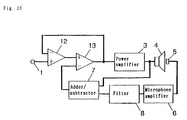
- Fig. 25 is a block diagram showing an acoustic reproducing apparatus according to embodiment 23 of the invention.
- Fig. 26 is a block diagram showing an acoustic reproducing apparatus according to embodiment 24 of the invention.
- Fig. 27 is a semi-sectional view showing the configuration of speaker and microphone of acoustic reproducing apparatus according to embodiments 25 to 30.
- Fig. 28 is a characteristic diagram showing the speaker frequency characteristic in embodiment 1.
- Fig. 29 is a characteristic diagram showing the frequency characteristic and phase characteristic of the power amplifier in embodiment 1.
- Fig. 30 is a characteristic diagram showing the frequency characteristic and phase characteristic of the filter in embodiment 3.
- Fig. 31 is a block diagram showing an acoustic reproducing apparatus according to embodiment 31 of the invention.
- Fig. 32 is a semi-sectional block diagram showing the speaker in the same embodiment.
- Fig. 33 is a frequency characteristic diagram of input signal of the acoustic reproducing apparatus in the same embodiment.
- Fig. 34 is a acoustic frequency characteristic diagram of acoustic output signal when the acoustic output of the passive radiator is controlled in the acoustic reproducing apparatus in the same embodiment.
- Fig. 35 is a acoustic frequency characteristic diagram of acoustic output signal when the acoustic output of the passive radiator is not controlled.
- Fig. 36 is an acoustic signal waveform diagram when the passive radiator is controlled in the acoustic reproducing apparatus in the same embodiment.
- Fig. 37 is an acoustic signal waveform diagram when the passive radiator is not controlled in the same acoustic reproducing apparatus.
- Fig. 38 is a block diagram showing an acoustic reproducing apparatus according to embodiment 32 of the invention.
- Fig. 39 is a block diagram showing an acoustic reproducing apparatus according to embodiment 33 of the invention.
- Fig. 40 is a block diagram showing an acoustic reproducing apparatus according to embodiment 34 of the invention.
- Fig. 41 is a block diagram showing an acoustic reproducing apparatus according to embodiment 35 of the invention.
- Fig. 42 is a block diagram showing an acoustic reproducing apparatus according to embodiment 36 of the invention.
- Fig.43 is a block diagram showing an acoustic reproducing apparatus according to embodiment 37 of the invention.
- Fig. 44 is a characteristic diagram showing the frequency characteristic and phase characteristic of the microphone output of the acoustic reproducing apparatus in embodiment 37.
- Fig. 45 is a block diagram showing an acoustic reproducing apparatus according to embodiment 38 of the invention.
- Fig. 46 is a block diagram showing an acoustic reproducing apparatus according to embodiment 39 of the invention.
- Fig. 47 is a block diagram showing a modified acoustic reproducing apparatus of embodiment 39 of the invention.
- Fig. 48 is a block diagram showing an acoustic reproducing apparatus according to embodiment 40 of the invention.
- Fig. 49 is a block diagram showing a modified acoustic reproducing apparatus of embodiment 40.
- Fig. 50 is a block diagram showing an acoustic reproducing apparatus according to embodiment 41 of the invention.
- Fig. 51 is a block diagram showing an acoustic reproducing apparatus according to embodiment 42 of the invention.
- Fig. 52 is a block diagram showing a modified acoustic reproducing apparatus of embodiment 42 of the invention.
- Fig. 53 is a block diagram showing an acoustic reproducing apparatus according to embodiment 43 of the invention.
- Fig. 54 is a block diagram showing a modified acoustic reproducing apparatus of embodiment 43 of the invention.
- Fig. 55 is a block diagram showing an acoustic reproducing apparatus according to embodiment 44 of the invention.
- Fig. 56 is a block diagram showing an acoustic reproducing apparatus according to embodiment 45 of the invention.
- Fig. 57 is a block diagram showing a constitution of an acoustic reproducing apparatus of a prior art.
- Fig. 58 is a block diagram showing the constitution of an acoustic reproducing apparatus using a passive radiator in a prior art.
- Fig. 59 is a characteristic diagram showing the acoustic reproduction frequency characteristic and phase characteristic in a prior art.
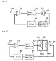
- Fig. 1 is a block diagram showing the constitution of acoustic reproducing apparatus of the first embodiment of the invention.
- a signal entering from an input terminal 1 is fed into a positive input terminal of a subtractor 2, and the output signal of the subtractor 2 is fed into a power amplifier 3 and is amplified.
- a speaker 4 is connected at the output side of the power amplifier 3, and an acoustic output from the speaker 4 is radiated. This acoustic output is detected by a microphone 5.
- the signal detected by the microphone 5 is amplified by a microphone amplifier 6, and its output signal and the output signal of the subtractor 2 are subtracted or added in an adder/subtractor 7.
- the output signal of the adder/subtractor 7 is fed into a negative input terminal of the subtractor 2, and a negative feedback circuit is composed.
- the adder/subtractor 7 is used as an adder when the output of the subtractor 2 is in positive phase to the output of the microphone amplifier 6 receiving the acoustic output signal of the speaker 4.
- the adder/subtractor 7 is used as a subtractor when the output of the subtractor 2 is in reverse phase to the output of the microphone amplifier 6 receiving the acoustic output signal of the speaker 4.
- phase relation varies with the phase relation and connection polarity of the inputs and outputs of the power amplifier 3, microphone 5 and microphone amplifier 6, and the phase characteristic to the frequency varies depending on the location of the microphone 5. It also varies with the combination of the filter and phase shift circuit as mentioned below, and whether the adder/subtractor 7 is used as adder or subtractor should be determined at the time of composing the circuit, which holds true also in the following embodiments.
- Fig. 28 compares the frequency characteristic of the speaker 4 corrected according to the embodiment with the uncorrected cases.
- Fig. 29 shows the output voltage characteristic relative to the frequency and the phase characteristic relative to the frequency of the power amplifier 3 corrected according to the embodiment.
- the position of the microphone 5 in the embodiment is located above the center pole of center of the lower plate 35 of the speaker 4 as shown in code 5e in Fig. 27 as specifically described in the following embodiments, and as shown in Fig. 28 it is known that the characteristic in the medium range (700 Hz to 1.5 kHz) for inducing edge resonance of the speaker 4 is improved.
- Fig. 2 is a block diagram showing the constitution of the acoustic reproducing apparatus in the second embodiment. As one of the input signals to the adder/subtractor 7, the signal from the output terminal of the power amplifier 3 is connected, and the other constitution is same as in Embodiment 1.
- Fig. 3 is a block diagram showing the constitution of the acoustic reproducing apparatus in the third embodiment.
- a filter 8 is inserted between the microphone amplifier 6 and adder/subtractor 7, and the other constitution is same as in Embodiment 1.
- Fig. 30 shows the characteristic of the filter 8, and the degree of amplification rises as becoming higher in frequency range.
- the phase characteristic of this filter has a phase advancement of about 60 degrees at 1.5 kHz.
- the phase characteristic of a speaker is delayed toward -180 degrees from the frequency band exceeding the piston motion range (about 800 Hz) as shown in Fig. 59, and the phase characteristic is disturbed in the split resonance region.
- edge resonance also occurs near the maximum frequency of piston motion, and fluctuations are significant depending on the speaker, and therefore both amplitude and phase may be unstable at the time of negative feedback. it is hence intended to maintain a phase allowance by inserting the filter 8 having such phase advancing characteristic as mentioned above into the output side of the microphone amplifier 6.
- the frequency characteristic of the filter 8 is also raised toward the high frequency range, in the place where the speaker frequency characteristic acoustically declines as becoming higher in frequency range, for example, at positions of codes 5e, 5f, 5g, 5h in Fig. 27 showing the microphone locations explained in detail below, by installing microphones 5 and correcting the phase with the filter 8 having above phase advancing characteristic, the band allowed to apply negative feedback stably can be expanded.
- Fig. 4 is a block diagram showing the constitution of the acoustic reproducing apparatus in the fourth embodiment.
- a filter 8 is inserted between the microphone amplifier 6 and adder/subtractor 7, and the other constitution is same as in Embodiment 2.
- the filter 8 having the phase advancing characteristic as shown in Fig. 30, the stability of the negative feedback system can be enhanced same as in Embodiment 3, and detailed description is omitted.
- Fig. 5 is a block diagram showing the constitution of the acoustic reproducing apparatus in the fifth embodiment.
- a high pass filter 11 and a second adder/subtractor 10 are added, in which the output signal of the microphone amplifier 6 and input signal of the power amplifier 3 are passes through the high pass filter 11 and fed into the second adder/subtractor 10, and the output signal added or subtracted in the second adder/subtractor 10 is connected so as to be negatively fed back to the subtractor 9.
- T(F) when T(F) is a frequency band for passing a signal, it becomes T(F) ⁇ 1, and the transmission function is Vout/Vin ⁇ A/3
- the same negative feedback as in Embodiment 1 is applied in the frequency cut-off band of the transmission function T(F) of the high pass filter 11, and when T(F) is passing frequency band, the degree of amplitude is constant regardless of the transmission function of the acoustic system including speaker 4 and the others.
- the first adder/subtractor 7 is used as subtractor and second adder/subtractor 10 as adder, but, depending on the condition, the first adder/subtractor 7 may be operated as adder, and the second adder/subtractor 10 as subtractor.
- Fig. 6 is a block diagram showing the constitution of the acoustic reproducing apparatus in the sixth embodiment. What differs from Embodiment 5 is that one input terminal of the first adder/subtractor 7 is connected to the output terminal of the power amplifier 3.
- the first adder/subtractor 7 is used as subtractor and second adder/subtractor 10 as adder, but, depending on the condition, the first adder/subtractor 7 may be operated as adder, and the second adder/subtractor 10 as subtractor.
- a seventh embodiment of the invention is described by reference to the drawing.
- Fig. 7 is a block diagram showing the constitution of the acoustic reproducing apparatus in the seventh embodiment.
- a filter 8 hiking in the degree of amplitude along with elevation in frequency range as shown in Fig. 30 used in Embodiment 3 is connected to the output of the microphone amplifier 6 in the circuit in Embodiment 5 in Fig. 5, and the first adder/subtractor 7 and high pass filter 11 are connected to the output of this filter 8, and the other constitution is same as in Embodiment 5.
- Fig. 8 is a block diagram showing the constitution of the acoustic reproducing apparatus in the eighth embodiment.
- the filter 8 used in Embodiment 3 is connected to the output of the microphone amplifier 6 of Embodiment 6 in Fig. 6, and the first adder/subtractor 7 and high pass filter 11 are serially connected to the output of this filter 8, and the other constitution is same as in Embodiment 6.
- Fig. 9 is a block diagram showing the constitution of the acoustic reproducing apparatus in the ninth embodiment.
- An input terminal 1 is connected to a positive input terminal of a first subtractor 12, an output terminal of the first subtractor 12 is connected to a positive input terminal of a second subtractor 13, an output terminal of the second subtractor 13 is connected to an input terminal of a power amplifier 3, the output of the power amplifier 3 is given to the speaker 4, the acoustic output of the speaker 4 is received by the microphone 5, and its output is fed into a microphone amplifier 6.
- the output of the microphone amplifier 6 is connected to the negative input terminal of the second subtractor 13, and the output terminal of the second subtractor 13 is connected to the negative input terminal of the first subtractor 12.
- the input signal of the power amplifier 3 is subtracted from the input signal in the first subtractor 12, and the output signal of the microphone amplifier 6 is subtracted from the output signal of the first subtractor 12 in the second subtractor 13, and its output signal is fed as input signal to the power amplifier 3.
- Fig. 10 is a block diagram showing the constitution of the acoustic reproducing apparatus in the tenth embodiment. What the embodiment differs from Embodiment 9 is that the output of the power amplifier 3 is connected to the negative input terminal of the first subtractor 12 connecting the input terminal 1, and the other constitution is same as in Embodiment 9, and the output signal of the power amplifier 3 is subtracted from the input signal in the first subtractor 12, and the output signal of the microphone amplifier 6 is subtracted from the output signal of the first subtractor 12 in the second subtractor 13, and its output signal is fed as input signal to the power amplifier 3.
- Fig. 11 is a block diagram showing the constitution of the acoustic reproducing apparatus in the eleventh embodiment, and in addition to the constitution of Embodiment 9, in this embodiment, the filter 8 used in Embodiment 3 is inserted between the output of the microphone amplifier 6 and negative input terminal of the second subtractor 13, and the other constitution is same as in Embodiment 9.
- the stability of the negative feedback system can be enhanced same as in Embodiment 3, and explanation of detail is omitted.
- Fig. 12 is a block diagram showing the constitution of the acoustic reproducing apparatus in the twelfth embodiment.
- the filter 8 used in Embodiment 3 is inserted between the microphone amplifier 6 and negative input terminal of the second subtractor 13, and the other constitution is same as in Embodiment 10.
- the stability of the negative feedback system can be enhanced same as in Embodiment 3, and explanation of detail is omitted.
- Fig. 13 is a block diagram showing the constitution of the acoustic reproducing apparatus in the thirteenth embodiment.
- an adder/subtractor 7 is provided between the microphone amplifier 6 and negative input terminal of the second subtractor 13, and the output signal of the second subtractor 13 is branched and connected to one input terminal of the adder/subtractor 7, and in this constitution, the output signal of microphone amplifier 6 and output signal of second subtractor 13 are added or subtracted in the adder/subtractor 7, and its output signal is connected to the negative input terminal of the second subtractor 13, output of the first subtractor 12 is connected in series to the front stage of the second subtractor 13, and the output signal of the second subtractor 13 is fed into the negative input terminal of the first subtractor 12.
- Fig. 14 is a block diagram showing the constitution of the acoustic reproducing apparatus in the fourteenth embodiment. What the embodiment differs from Embodiment 13 is that the output signal of the power amplifier 3 is connected to the input of the adder/subtractor 7 and negative input terminal of the first subtractor 12, and the other constitution is same as in Embodiment 13.
- Fig. 15 is a block diagram showing the constitution of the acoustic reproducing apparatus in the fifteenth embodiment.
- the filter 8 used in Embodiment 3 is inserted between the output of the microphone amplifier 6 and one input of the adder/subtractor 7, and the other constitution is same as in Embodiment 13.
- the stability of the negative feedback system can be enhanced same as in Embodiment 3, and explanation of detail is omitted.
- Fig. 16 is a block diagram showing the constitution of the acoustic reproducing apparatus in the sixteenth embodiment.
- the filter 8 used in Embodiment 3 is inserted between the output of the microphone amplifier 6 and one input of the adder/subtractor 7, and the other constitution is same as in Embodiment 14.
- the stability of the negative feedback system can be enhanced same as in Embodiment 3, and explanation of detail is omitted.
- Fig. 17 is a block diagram showing the constitution of the acoustic reproducing apparatus in the seventeenth embodiment.
- a second subtractor 13 is used, and the output terminal of the first subtractor 12 is connected to a positive input terminal of the second subtractor 13, an input terminal 1 for signal input is connected to the positive input terminal of the first subtractor 12, and the output signal of the power amplifier 3 is connected to its negative input terminal.
- Fig. 18 is a block diagram showing the constitution of the acoustic reproducing apparatus in the eighteenth embodiment.
- a second subtractor 13 instead of the subtractor 2 provided in the input unit in Embodiment 2, a second subtractor 13 is used, and the output terminal of the first subtractor 12 is connected to a positive input terminal of the second subtractor 13, an input terminal 1 for signal input is connected to the positive input terminal of the first subtractor 12, and the output signal of the second subtractor 13 is connected to negative input terminal of the first subtractor 12.
- a nineteenth embodiment of the invention is described by reference to the drawing.
- Fig. 19 is a block diagram showing the constitution of the acoustic reproducing apparatus in the nineteenth embodiment.
- the filter 8 used in Embodiment 3 is inserted between the output of the microphone amplifier 6 and one input of the adder/subtractor 7, and the other constitution is same as in Embodiment 17.
- the stability of the negative feedback system can be enhanced same as in Embodiment 3, and explanation of detail is omitted.
- a twentieth embodiment of the invention is described by reference to the drawing.
- Fig. 20 is a block diagram showing the constitution of the acoustic reproducing apparatus in the twentieth embodiment.
- the filter 8 used in Embodiment 3 is inserted between the output of the microphone amplifier 6 and one input of the adder/subtractor 7, and the other constitution is same as in Embodiment 18.
- the stability of the negative feedback system can be enhanced same as in Embodiment 3, and explanation of detail is omitted.
- Fig. 21 is a block diagram showing the constitution of the acoustic reproducing apparatus in the twenty-first embodiment
- Fig. 22 is a further specific block diagram.
- Fig. 21 shows a basic block diagram for applying an acoustic negative feedback by using a plurality each of speakers and microphones and one power amplifier 3.
- filters 14a, 14b, 14c which divide the bands of speakers 4a, 4b, 4c
- filters 16a, 16b, 16c which are connected to outputs of negative feedback circuits 15a, 15b, 15c are used in combination.
- the negative feedback circuits 15a, 15b, 15c herein may be composed of any circuit designed to add or subtract the input of power amplifier 3 and output of microphone amplifier 6 (or output through filter) as disclosed in Embodiments 1 through 20.
- Fig. 22 shows the circuit structure in Fig. 21 more specifically, and a two-way speaker system is constituted herein, and a low pass circuit is composed of a coil 18 and a high pass circuit a capacitor 19, which are respectively connected to a bass speaker 4d and a treble speaker 4e.
- the outputs of microphones 5a, 5b corresponding to the speakers are amplified in microphone amplifiers 6a, 6b, added or subtracted with output signals of subtractors 2a, 2b connected to one of inputs thereof in adders/subtractors 7a, 7b, and connected to negative input terminals of the subtractors 2a, 2b.
- the outputs of the subtractors 2a, 2b are passed through filters 16e, 16d, and added and fed into a power amplifier 3.
- the filters 16e, 16d have the same characteristic as the low pass circuit of the coil 18 of the output filter of the power amplifier 3 and the high pass circuit of the capacitor 19, and suppress interference between the speakers 4d, 4d due to the microphones 5a, 5b.
- a negative feedback can be applied to a multi-way speaker system.
- Fig. 23 is a block diagram showing the constitution of the acoustic reproducing apparatus in the twenty-second embodiment
- Fig. 24 is a block diagram showing its specific constitution.
- microphones 5a to 5c are used as many as the number (three in this embodiment) of speakers 4a to 4c
- a negative feedback circuit 20 is provided to feed back negatively to one subtractor after adding or subtracting process by disposing filters at outputs of the microphones 5a to 5c.
- a coil 18 of low pass circuit (filter) and a capacitor 19 of high pass circuit (filter) are connected to the output of the power amplifier 3, and are further connected to a bass speaker 4d and a treble speaker 4e respectively.
- Their acoustic outputs are detected by microphones 5a, 5b, amplified by microphone amplifiers 6a, 6b, passed through filters 8a, 8b, fed into adders/subtractors 7a, 7b, and added or subtracted with the output signal of the subtractor 2, and the outputs are connected to a negative input terminal of the subtractor 2.
- Fig. 25 is a block diagram showing the constitution of the acoustic reproducing apparatus in the twenty-third embodiment.
- the acoustic reproducing apparatus possessing a tone adjusting function is composed of a negative feedback circuit and a voltage control amplifier, and it is optimum in the case of presence of limitation in the dynamic range of the system, for example, acoustic reproducing apparatus for mobile audio system or hall acoustic system.
- the signal entered from an input terminal 1 passes through a voltage control amplifier 21, a tone adjusting filter 22 (for example, a graphic equalizer), and a negative feedback circuit 23, and is fed into a power amplifier 3.
- This negative feedback circuit 23 may be composed of any circuit designed to add or subtract the input signal of the power amplifier 3 and output of the microphone amplifier 6 (or a filter output) as disclosed in Embodiments 1 to 22.
- the dynamic range lacks in a high level portion of input signal, and the output of the power amplifier may be clipped, but in this embodiment, in order to solve this problem, the input voltage of the power amplifier 3 is detected by a level detector 24, and by setting an input voltage (output voltage of the negative feedback circuit 23) not to cause to clip the output of the power amplifier 3, when an input voltage exceeding the set voltage is detected, it is converted into a DC voltage in an AC/DC converter 25, and the degree of amplification of the voltage control amplifier 21 is lowered by this voltage.
- the clip of the power amplifier 3 can be limited to a minimum regardless of the adjusting state of the frequency characteristic of the acoustic adjusting filter 22 or the state of negative feedback system.
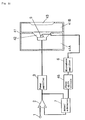
- Fig. 26 is a block diagram showing the constitution of the acoustic reproducing apparatus in the twenty-fourth embodiment, and in this embodiment, when the constitution of the power amplifier 3 used in Embodiments 1 to 2 3 is different, that is, in a mobile audio system, when a power amplifier 26 is connected in BTL (balanced transformer-less) structure, and a DC voltage of about half of the supply (battery) voltage is applied between its output terminal and the ground, only a DC component is picked up from the output of the power amplifier 26, and is used as a power source for a microphone 27.
- BTL balanced transformer-less
- a DC voltage of about 7 V is applied between the output terminal (positive output, negative output) of the BTL-connected power amplifier 26 and the ground, and AC signals are adding in reverse phase to each other on the basis of this voltage.
- AC signals are adding in reverse phase to each other on the basis of this voltage.
- resistors 28, 29, AC components in reverse phase to each other are removed, and only DC components (about 7 V) can be taken out.
- a capacitor 30 composes a low pass filter together with the resistors 28, 29, and the DC voltage is stabilized.
- the microphone 27 generally, an electret condenser microphone is used, and a field effect transistor is built in a microphone capsule, and a register 31 is for bias register of the field effect transistor, and a microphone output signal is taken out from one end 32 at the microphone 27 side of the register 31.
- a shield wire is used for prevention of induced noise as the connection cord of the microphone 27, but in the constitution of the embodiment it is possible to lower the output resistance of the microphone 27, and if the connection cord is a single wire, it is less susceptible to noise effect.
- Embodiments 25 to 30 below relate to changes of configuration of microphone explained in the foregoing Embodiments 1 to 24, and, to begin with, a twenty-fifth embodiment of the invention is described below by reference to the drawing.
- Fig. 27 shows the speaker for the acoustic reproducing apparatus of Embodiments 25 to 30, and in the twenty-fifth embodiment, specifically, the microphone 5d for detecting acoustic output signals is disposed on the front side of a dust cap 34 coupled in the middle of a diaphragm 33.
- the frequency characteristic can be detected over an almost entire frequency range generated from the speaker.
- the microphone 5e for detecting acoustic output signals in Fig. 27 is disposed before the center pole of a lower plate 35 for composing a magnetic circuit.
- the characteristic is such that signals are detected from low frequency range to the limit value of piston motion, while higher frequency components attenuate.
- the microphone 5f for detecting acoustic output signals in Fig. 27 is disposed in lower part (rear part in the position being installed in speaker box) of a central hole of the lower plate 35.
- the characteristic is such that the resonance (peak) of the central hole of the lower plate 35 appears in the high frequency range, while higher frequency components attenuate.
- the microphone 5g for detecting acoustic output signals in Fig. 27 is disposed between the center pole of the lower plate 35 for composing a magnetic circuit and a magnet 36.
- the microphone 5h for detecting acoustic output signals in Fig. 27 is disposed between the lower side of a suspension 38 for supporting a voice coil 40 and a frame 39 (or an upper plate 37).
- the characteristic is similar to that of Embodiment 25, that is, high frequency range attenuates smoothly while detecting almost all frequency range of the acoustic output issued by the speaker.
- the microphone 5i for detecting acoustic output signals in Fig. 27 is disposed between the diaphragm 33 and frame 39.
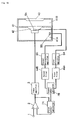
- Fig. 31 is a block diagram showing the constitution of the acoustic reproducing apparatus in the thirty-first embodiment.
- the signal entering from an input terminal 1 is fed into a positive input terminal of a subtractor 2, and an output signal of the subtractor 2 is fed into a power amplifier 3 and is amplified.
- a speaker 42 is connected at the output side of the power amplifier 3, and an acoustic output is radiated from the speaker 42. This acoustic output is detected by a microphone 5.
- the signal detected by the microphone 5 is amplified by a microphone amplifier 6, and its output signal and the output signal of the subtractor 2 are subtracted or added in an adder/subtractor 7.
- the output signal of the adder/subtractor 7 is fed into a negative input terminal of the subtractor 2, thereby composing a negative feedback circuit.
- constituted negative feedback circuit is same as Embodiment 1 electrically.
- a speaker box 41 forms enclosed spaces 41A, 41B communicating in the longitudinal direction, and the speaker 42 is coupled to the enclosed space 41A at the rear chamber side, and a passive radiator 43 is coupled to the enclosed space 41B at the front chamber side, and the passive radiator 43 is driven through the air in the enclosed space 41B by driving of the speaker 42, thereby reproducing acoustically.
- Fig. 32 is a semi-sectional view showing only one side from the central line axis-symmetrical of the sectional view of the speaker 42 coupled to the speaker box 41.
- the microphone 5 is disposed in the central front part of the magnetic circuit 42A of the speaker 42, and an acoustic output signal generated in a space enclosed by a voice coil 42B and dust cap 42C is detected, and it is composed to apply a negative feedback by using the detected acoustic signal.
- the input signal amplified in the power amplifier 3 through the subtractor 2 from the input terminal 1 is reproduced by the speaker 42 shown in Fig. 32, and the acoustic output signal radiated from the speaker 42 is detected by a microphone 5, and the output signal of the microphone 5 is amplified in the microphone amplifier 6, and the output signal of the microphone amplifier 6 and the output signal of the subtractor 2 connected to the input terminal 1 are added or subtracted in the adder/subtractor 7, and fed into the negative input terminal of the subtractor 2.
- the transmission function in the block diagram of the acoustic reproducing apparatus of the prior art explained in Fig. 58 was as follows as mentioned above.
- T(S) is a transmission function of acoustic system composed of speaker 42, passive radiator 43, and front and rear enclosed spaces 41A, 41B, and when the phase difference of the signal delivered from the power amplifier 3 by resonance (low frequency range resonance) composed of the speaker 42, passive radiator 43 and enclosed spaces 41A, 41B, and the output signal of the microphone 5 is changed by 180 degrees to the plus or minus side (the phase is inverted), T(S) is minus 1, and supposing the degree of amplitude A of the power amplifier 3 to be 1, the denominator is 0 and oscillation occurs in the circuit of the prior art, but the transmission function is 1 in the circuit of the embodiment, and it is known possible to keep stability of the negative feedback in the same condition.
- the position of the microphone 5 is very large in sound pressure, and incoming noise is substantially attenuated by the passive radiator 43, and hence a high S/N ratio is obtained.
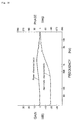
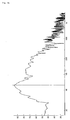
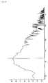
- Fig. 33, Fig. 34, and Fig. 35 respectively show the frequency characteristic of the input signal of the acoustic reproducing apparatus of the embodiment, the frequency characteristic by control of the acoustic output of the passive radiator 43 by negative feedback circuit, and the frequency characteristic without control of the acoustic output of the passive radiator 43, and it is known that the characteristic by negative feedback in Fig. 34 is closer to the input original signal shown in Fig. 33.
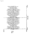
- Fig. 36 shows an acoustic signal waveform radiated from the passive radiator 43 when 60 Hz tone burst waves (10 waves ON, 1 wave OFF) are entered in the case of control of acoustic output of the passive radiator 43 by the negative feedback circuit in Fig. 31.
- Fig. 37 shows an acoustic signal waveform without such control. Comparing them and taking note of the 1-wave OFF portion, it is known that the signal waveform with control of acoustic output is decreased in level as compared with the signal waveform without control. It proves that the rise and fall characteristics of the passive radiator 43 are improved by the control.
- FIG. 38 is a block diagram showing the constitution of the acoustic reproducing apparatus in the embodiment.
- a phase shift circuit 45 is inserted between the microphone amplifier 6 and adder/subtractor 7 of Embodiment 31, and the other constitution is same as in Embodiment 31 in Fig. 31.
- FIG. 39 is a block diagram showing the constitution of the acoustic reproducing apparatus in the embodiment.
- a filter 44 and a phase shift circuit 45 are serially inserted between the microphone amplifier 6 and adder/subtractor 7 of Embodiment 31, and the other constitution is same as in Embodiment 31 in Fig. 31.
- Fig. 40 is a block diagram showing the constitution of the acoustic reproducing apparatus in the embodiment.
- the output of the microphone amplifier 6 in Embodiment 31 is branched into two, and the branched outputs are fed into a first filter 46A and a second filter 46B mutually different in characteristic.
- the output of the first filter 46A and the output of the second filter 46B passing through an inverting circuit 47 are fed into an adder 48, and the output of the adder 48 is fed into the adder/subtractor 7, and the other constitution is same as in Embodiment 31 in Fig. 31.
- Fig. 41 is a block diagram showing the constitution of the acoustic reproducing apparatus in the embodiment.
- a phase shift circuit 45 is used, and the other constitution is same as in Embodiment 34 in Fig. 40.
- the degree of freedom for control for improving the tone and frequency characteristic of the system can be extended same as in Embodiment 34.
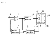
- FIG. 42 is a block diagram showing the constitution of the acoustic reproducing apparatus in the embodiment.
- the location of the microphone 5 shown in Embodiment 31 in Fig. 31 is disposed within the rear side enclosed space 41A of the speaker 42, and the other constitution is same as in Embodiment 31.
- the output signal of a power amplifier 3 is connected to the speaker 42, and the speaker 42 is driven to cause a pressure change in the front enclosed space 41B.
- the pressure change in the rear enclosed space 41A reaches the maximum at the frequency where the speaker 42 and passive radiator 43 resonate in phase, and becomes the minimum when the speaker 42 and passive radiator 43 resonate in reverse phase.
- the transient characteristic can be improved.
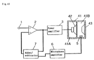
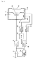
- FIG. 43 is a block diagram showing the constitution of the acoustic reproducing apparatus in the embodiment.
- the location of the microphone 5 shown in Embodiment 31 in Fig. 31 is disposed in the front side enclosed space 41B of the speaker 42, and the other constitution is same as in Embodiment 31.
- the signal entering from an input terminal 1 is fed into a positive input terminal of a subtractor 2, and the output of the subtractor 2 is amplified in a power amplifier 3, and the speaker 42 is driven by its signal.
- the pressure change of this speaker 42 is transmitted to the air in the front enclosed space 41B of the speaker 42, and the pressure change in this enclosed space 41B is transmitted to a passive radiator 43, and an acoustic output is radiated outside by the vibration of the passive radiator 43.
- the pressure change of the front enclosed space 41B of the speaker 42 for vibrating the passive radiator 43 is detected by the microphone 5.
- the detected signal is amplified by the microphone amplifier 6, the output of the microphone amplifier 6 and the output signal of the subtractor 2 connected to the input terminal 1 are fed into an adder/subtractor 7 to be subtracted or added in the adder/subtractor 7.
- the output signal of the adder/subtractor 7 is connected to a negative input terminal of the subtractor 2, and a negative feedback circuit is constituted.
- the adder/subtractor 7 is used as an adder when the output signal of the microphone 5 is in phase with the input signal of the input terminal 1, and as a subtractor when in reverse phase.
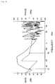
- Fig. 44 shows the output frequency characteristic of the microphone 5 in the front enclosed space 41B of the speaker 42 of the acoustic reproducing apparatus of the embodiment, in which two resonance peaks f01 and f02 are present, and the phase makes one revolution between them. It is also known that the sound pressure is decreased in the phase inverting portion between f01 and f02.
- the tone burst output waveform (10 waves ON, 1 wave OFF) has the characteristic same as shown in Fig. 36 and Fig. 37, respectively, and when controlled, the output is evidently stopped in 1-wave OFF time.
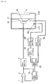
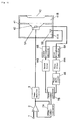
- FIG. 45 is a block diagram showing the constitution of the acoustic reproducing apparatus in the embodiment.
- two microphones for detecting the acoustic output signal radiated from the speaker 42 are disposed in the speaker box, with the first microphone 5A disposed at the front side of a magnetic circuit of the speaker 42, and the second microphone 5B in the rear enclosed space 41A of the speaker box 41.
- the output signals of the two microphones 5A, 5B are respectively connected to first and second microphone amplifiers 6A, 6B, and the output signals of the first and second microphone amplifiers 6A, 6B are fed into a second adder/subtractor 7B, and the output signal of the second adder/subtractor 7B and the output of a subtractor 2 are fed into a first adder/subtractor 7A, and the output signal of the first adder/subtractor 7A is connected to a negative input terminal of the subtractor 2, thereby constituting a negative feedback circuit.
- the in-phase portion of low frequency (below f01) shown in Fig. 44, and negative feedback signals of over 500 Hz totally inverted in phase can be decreased, and in the reproduced band of over f01 in Fig. 44, it is known stable if the negative feedback amount is increased.
- the second adder/subtractor 7B as an adder, and adding such a signal as to cause the output signals of the first and second microphone amplifiers 6A, 6B to be in reverse phase to the input signals, and further adding the output signal of the second adder/subtractor 7B by the first adder/subtractor 7A, signals for low frequency range reproduction cutting off high frequency components can be produced, and it is possible to present a system having the degree of freedom for controlling the tone and frequency characteristic of the speaker system higher than in the foregoing embodiments.
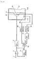
- Fig. 46 and Fig. 47 are block diagrams showing the constitution of the acoustic reproducing apparatus in the embodiment.
- a filter 44 is connected to the output of the second microphone amplifier 6B for amplifying the output signal of the second microphone 5B installed in the rear enclosed space 41A of the speaker box 41 in Embodiment 38 in Fig. 45, and the output signal of this filter 44 and the output signal of the first microphone amplifier 6A connected to the first microphone 5A installed in the front side of the magnetic circuit of the speaker 42 are fed into the second adder/subtractor 7B.
- a filter 44 is connected to the output signal of the first microphone amplifier 6A, and the output signal of this filter 44 and the output signal of the second microphone amplifier 6B are fed into the second adder/subtractor 7B, and in Fig. 46 and Fig. 47 the other constitution is same as in Embodiment 38 in Fig. 45.
- the positive feedback amount can be decreased.
- the degree of freedom of control is further increased, and so that the tone and frequency characteristic of the speaker system can be created more precisely.
- Fig. 48 and Fig. 49 are block diagrams showing the constitution of the acoustic reproducing apparatus in the embodiment.
- a phase shift circuit 45 is used instead of the filter 44 in Embodiment 39 shown in Fig. 46 and Fig. 47, and in the embodiment shown in Fig. 48, the phase shift circuit 45 is connected to the output of the second microphone amplifier 6B, and the output signal of the phase shift circuit 45 and the output signal of the first microphone amplifier 6A are fed into the second adder/subtractor 7B.
- the phase shift circuit 45 is connected to the output signal of the first microphone amplifier 6A, and the output signal of the phase shift circuit 45 and the output signal of the second microphone amplifier 6B are fed into the second adder/subtractor 7B, and in Fig. 48 and Fig. 49 the other constitution is same as in Embodiment 39 in Fig. 46 and Fig. 47.
- the band over f01 shown in Fig. 44 is inverted by the phase shift circuit 45, and when the second adder/subtractor 7B is used as a subtractor, it is possible to decrease signals less than f01 where the phase of output signals of the first microphone amplifier 6A and second microphone amplifier 6B are in phase with input signals, and signals in medium and high frequency range where both output signals of the first microphone amplifier 6A and second microphone amplifier 6B are in reverse phase to input signals, so that the negative feedback signals having the band limited in the reproducing band of the speaker system can be created.
- the phase of the negative feedback signal can be matched by using the phase shift circuit 45 for inverting the phase at a frequency point where the phase is reverse, so that the decrease of negative feedback signals can be prevented.
- Fig. 50 is a block diagram showing the constitution of the acoustic reproducing apparatus in the embodiment.
- the output of the first microphone amplifier 6A is fed to a first filter 44A
- the output signal of the second microphone amplifier 6B is fed to a second filter 44B
- the output signal of the first filter 44A and the output signal of the second filter 44B are connected to the second adder/subtractor 7B, and the other constitution is same as in Embodiment 38.
- band limitation is applied to the output signals of the two microphones 5A, 5B, and only the band in which the output signals of the microphones 5A, 5B are in phase with input signals is picked up, and the second adder/subtractor 7B is used as an adder, or the band in which the signal of one microphone is in phase with the input signal is picked up, and the band in which the input signal of the other microphone is in reverse phase to the input signal is picked up, and the second adder/subtractor 7B is used as a subtractor, and therefore as compared with the case of one microphone, a deeper negative feedback can be applied, or negative feedback can be applied in a wider band.
- Fig. 51 and Fig. 52 are block diagrams showing the constitution of the acoustic reproducing apparatus in the embodiment.
- the output signal of the first microphone amplifier 6A is fed into the filter 44
- the output signal of the second microphone amplifier 6B is fed into the phase shift circuit 45
- the output signal of the filter 44 and the output signal of the phase shift circuit 45 are connected to the second adder/subtractor 7B, and the other constitution is same as in Embodiment 38.
- the output signal of the first microphone amplifier 6A is fed into the phase shift circuit 45, and the output signal of the second microphone amplifier 6B is fed into the filter 44, and moreover the output signal of the filter 44 and the output signal of the phase shift circuit 45 are connected to the second adder/subtractor 7B, and the other constitution is same as in Embodiment 38.
- negative feedback control is effected by using the output signal of the microphone connected to the phase shift circuit 45 side as the main signal, and furthermore at a frequency desired to increase the negative feedback amount, or at a frequency desired to decrease the negative feedback amount, by processing another microphone signal in the filter 44 and adding or subtracting in the second adder/subtractor 7B, the frequency range of negative feedback and negative feedback amount can be controlled, so that the range for controlling the tone and frequency characteristic of the system can be expanded.
- Fig. 53 and Fig. 54 are block diagrams showing the constitution of the acoustic reproducing apparatus in the embodiment.
- the output signal of the first microphone amplifier 6A is fed into the a first filter 44A, and the output signal of the first filter 44A is fed into the phase shift circuit 45, and moreover the output signal of the phase shift circuit 45, and the output signal of the second microphone amplifier 6B passing through a second filter 44B are connected to the second adder/subtractor 7B, and the other constitution is same as in Embodiment 38.
- the output signal of the second microphone amplifier 6B is fed into the phase shift circuit 45 through the second filter 44B, and the output signal of the phase shift circuit 45, and the output signal of the first microphone amplifier 6A passing through the first filter 44A are connected to the second adder/subtractor 7B, and the other constitution is same as in Embodiment 38.
- Fig. 55 is a block diagram showing the constitution of the acoustic reproducing apparatus of the embodiment.
- a second microphone 5B is disposed in a front enclosed space 41B of a speaker 42
- a first microphone 5A is disposed in a space (front side of magnetic circuit) composed by the pole piece central part and dust cap of the speaker 42, and the other constitution is same as in Embodiment 38 in Fig. 45.
- the operating state of the diaphragm of the speaker 42, and the pressure of the enclosed space 41B for driving a passive radiator 43 can be detected.
- the transient characteristic is improved by applying a negative feedback by the first microphone 5A at the rise of action of the speaker 42, and if the passive radiator 43 is not put in action despite start of action of the speaker 42, the internal pressure of the front enclosed space 41B is raised, and this information is detected by the second microphone 5B.
- the pressure in the front enclosed space 41B of the speaker 42 is further heightened, and the rise time of the passive radiator 43 may be much shortened.
- the transient characteristic can be greatly improved.
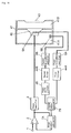
- FIG. 56 is a block diagram showing the constitution of the acoustic reproducing apparatus of the embodiment.
- a first microphone 5A for pressure detection is disposed in a rear enclosed space 41A of a speaker 42
- a second microphone 5B is disposed in a front enclosed space 41B of the speaker 42.
- the first and second microphones 5A and 5B are respectively connected to first and second microphone amplifiers 6A and 6B, and the output signals of the first and second microphone amplifiers 6A and 6B are connected to a second adder/subtractor 7B, and the output signal of the second adder/subtractor 7B and the output signal of a subtractor 2 are connected to a first adder/subtractor 7A, and the other constitution is same as in Embodiment 44 explained by reference to Fig. 55.
- the pressure change of vibration of the speaker 42 and passive radiator 43 in phase is detected by the first microphone 5A, and the pressure change of vibration in reverse phase is detected by the second microphone 5B, so that pressure changes in all resonances can be detected.
- the feedback can be canceled in the frequency band where the phase is reverse in the rear enclosed space 41A and front enclosed space 41B of the speaker 42, and the output sound pressure below the minimum resonance frequency can be elevated.
- the second adder/subtractor 7B as a subtractor, it is also possible to apply a deeper negative feedback when the speaker 42 and passive radiator 43 resonate in reverse phase, and the negative feedback to such resonance of the speaker system may be applied more precisely.
- the negative feedback may be applied deeply or stably, and the merits of negative feedback may be fully utilized, and the acoustic characteristic of the speaker and its surrounding can be improved, so that an excellent characteristic may be obtained.
- the acoustic characteristic of the speaker system having the passive radiator coupled in the front enclosed space of the speaker may be notably improved, and moreover since the detection signal of the microphone is used as the reference, the acoustic characteristic is corrected automatically if the characteristic of the speaker or passive radiator is changed, and the contribution of these outstanding effects is beautiful.
Landscapes
- Physics & Mathematics (AREA)
- Engineering & Computer Science (AREA)
- Acoustics & Sound (AREA)
- Signal Processing (AREA)
- Circuit For Audible Band Transducer (AREA)
Applications Claiming Priority (3)
| Application Number | Priority Date | Filing Date | Title |
|---|---|---|---|
| JP30901593 | 1993-12-09 | ||
| JP309015/93 | 1993-12-09 | ||
| JP30901593 | 1993-12-09 |
Publications (2)
| Publication Number | Publication Date |
|---|---|
| EP0658064A2 true EP0658064A2 (de) | 1995-06-14 |
| EP0658064A3 EP0658064A3 (de) | 2004-09-01 |
Family
ID=17987859
Family Applications (1)
| Application Number | Title | Priority Date | Filing Date |
|---|---|---|---|
| EP94119350A Withdrawn EP0658064A3 (de) | 1993-12-09 | 1994-12-07 | Tonwiedergabegerät |
Country Status (1)
| Country | Link |
|---|---|
| EP (1) | EP0658064A3 (de) |
Cited By (10)
| Publication number | Priority date | Publication date | Assignee | Title |
|---|---|---|---|---|
| WO1999021395A1 (de) * | 1997-10-22 | 1999-04-29 | Fraunhofer-Gesellschaft zur Förderung der angewandten Forschung e.V. | Adaptiver akustischer monitor |
| WO1999014980A3 (en) * | 1997-09-17 | 1999-06-03 | Frank Albert Bilan | A loudspeaker with lead wires extending through the magnetic assembly and integrated with an amplifier |
| GB2292854B (en) * | 1994-08-12 | 1999-08-25 | Motorola Ltd | Electronic audio device and method of operation |
| WO2001041500A3 (en) * | 1999-12-01 | 2002-05-10 | Matsushita Electric Industrial Co Ltd | Loudspeaker device |
| EP1059831A4 (de) * | 1998-12-01 | 2004-08-18 | Matsushita Electric Industrial Co Ltd | Lautsprechergerät |
| US20090041259A1 (en) * | 2005-04-07 | 2009-02-12 | Andre Grandt | Headphones for Connection to an External Active Noise Compensation Device |
| US9743181B2 (en) | 2016-01-06 | 2017-08-22 | Apple Inc. | Loudspeaker equalizer |
| US9961464B2 (en) | 2016-09-23 | 2018-05-01 | Apple Inc. | Pressure gradient microphone for measuring an acoustic characteristic of a loudspeaker |
| US10244314B2 (en) | 2017-06-02 | 2019-03-26 | Apple Inc. | Audio adaptation to room |
| US10425733B1 (en) | 2018-09-28 | 2019-09-24 | Apple Inc. | Microphone equalization for room acoustics |
Families Citing this family (1)
| Publication number | Priority date | Publication date | Assignee | Title |
|---|---|---|---|---|
| EP1575293A1 (de) * | 2004-03-11 | 2005-09-14 | Canal+ Technologies | Dynamische Verwaltung von Chipkarten |
Family Cites Families (5)
| Publication number | Priority date | Publication date | Assignee | Title |
|---|---|---|---|---|
| GB2147166B (en) * | 1983-09-26 | 1986-11-05 | Graham Potter | Apparatus and method for providing an undistorted output signal from a non-linear device |
| JPS60263598A (ja) * | 1984-06-11 | 1985-12-27 | Matsushita Electric Ind Co Ltd | ハウリング抑圧装置 |
| GB8725240D0 (en) * | 1987-10-28 | 1987-12-02 | Thomas I G | Differential volume adjusters |
| JP2717139B2 (ja) * | 1989-03-03 | 1998-02-18 | 日本電信電話株式会社 | 音圧制御装置 |
| JPH04302300A (ja) * | 1991-03-29 | 1992-10-26 | Aiwa Co Ltd | バスレフ形スピーカの駆動装置 |
-
1994
- 1994-12-07 EP EP94119350A patent/EP0658064A3/de not_active Withdrawn
Cited By (18)
| Publication number | Priority date | Publication date | Assignee | Title |
|---|---|---|---|---|
| GB2292854B (en) * | 1994-08-12 | 1999-08-25 | Motorola Ltd | Electronic audio device and method of operation |
| WO1999014980A3 (en) * | 1997-09-17 | 1999-06-03 | Frank Albert Bilan | A loudspeaker with lead wires extending through the magnetic assembly and integrated with an amplifier |
| US6243472B1 (en) | 1997-09-17 | 2001-06-05 | Frank Albert Bilan | Fully integrated amplified loudspeaker |
| WO1999021395A1 (de) * | 1997-10-22 | 1999-04-29 | Fraunhofer-Gesellschaft zur Förderung der angewandten Forschung e.V. | Adaptiver akustischer monitor |
| DE19746645C1 (de) * | 1997-10-22 | 1999-05-20 | Fraunhofer Ges Forschung | Adaptiver akustischer Monitor |
| US7065221B1 (en) | 1998-12-01 | 2006-06-20 | Matsushita Electric Industrial Co., Ltd. | Speaker apparatus |
| EP1059831A4 (de) * | 1998-12-01 | 2004-08-18 | Matsushita Electric Industrial Co Ltd | Lautsprechergerät |
| CN100534222C (zh) * | 1998-12-01 | 2009-08-26 | 松下电器产业株式会社 | 扬声器装置 |
| US7058186B2 (en) | 1999-12-01 | 2006-06-06 | Matsushita Electric Industrial Co., Ltd. | Loudspeaker device |
| WO2001041500A3 (en) * | 1999-12-01 | 2002-05-10 | Matsushita Electric Industrial Co Ltd | Loudspeaker device |
| CN100539738C (zh) * | 1999-12-01 | 2009-09-09 | 松下电器产业株式会社 | 扬声器设备 |
| US20090041259A1 (en) * | 2005-04-07 | 2009-02-12 | Andre Grandt | Headphones for Connection to an External Active Noise Compensation Device |
| US8243942B2 (en) | 2005-04-07 | 2012-08-14 | Sennheiser Electronic Gmbh & Co. Kg | Headphones for connection to an external active noise compensation device |
| US9743181B2 (en) | 2016-01-06 | 2017-08-22 | Apple Inc. | Loudspeaker equalizer |
| US9961464B2 (en) | 2016-09-23 | 2018-05-01 | Apple Inc. | Pressure gradient microphone for measuring an acoustic characteristic of a loudspeaker |
| US10244314B2 (en) | 2017-06-02 | 2019-03-26 | Apple Inc. | Audio adaptation to room |
| US10299039B2 (en) | 2017-06-02 | 2019-05-21 | Apple Inc. | Audio adaptation to room |
| US10425733B1 (en) | 2018-09-28 | 2019-09-24 | Apple Inc. | Microphone equalization for room acoustics |
Also Published As
| Publication number | Publication date |
|---|---|
| EP0658064A3 (de) | 2004-09-01 |
Similar Documents
| Publication | Publication Date | Title |
|---|---|---|
| US5412734A (en) | Apparatus and method for reducing acoustic feedback | |
| US8565448B2 (en) | Dynamic bass equalization with modified Sallen-Key high pass filter | |
| EP0658064A2 (de) | Tonwiedergabegerät | |
| KR19990072901A (ko) | 저역통과필터피드백없이위상지연이없는d급증폭기 | |
| US6122385A (en) | Sound reproduction apparatus with stable feedback | |
| US20040042625A1 (en) | Equalization and load correction system and method for audio system | |
| US6990207B2 (en) | Active noise control system | |
| GB2274958A (en) | Video camera microphone circuits | |
| EP0951201B1 (de) | Audiowiedergabegerät | |
| JP2820899B2 (ja) | 電力増幅装置及びこれを具えるマルチウェイスピーカ装置 | |
| US11638095B2 (en) | Method and apparatus for improving effective signal-to-noise ratio of analog to digital conversion for multi-band digital signal processing devices | |
| US20220038059A1 (en) | Window based supply voltage conditioning circuit for noise filtering | |
| JP3147662B2 (ja) | 音響再生装置 | |
| JP3106718B2 (ja) | スピーカ駆動装置 | |
| JP4224892B2 (ja) | スピーカ装置 | |
| JP4978409B2 (ja) | デジタル増幅装置 | |
| JP2535232B2 (ja) | 音声出力回路 | |
| US7816980B2 (en) | Audio power amplifier using virtual ground and method of processing signal in the audio power amplifier | |
| JP2002345076A (ja) | 音響再生装置 | |
| US7079660B2 (en) | Bass compensation device and a sound system using the device | |
| WO2002013573A1 (en) | Loudspeaker device | |
| KR100506039B1 (ko) | 골전도 보청기의 제어장치 및 방법 | |
| JP3055204B2 (ja) | 周波数帯域分割装置 | |
| JP3231949B2 (ja) | 受話信号周波数特性補正方式 | |
| US10542345B2 (en) | Virtual bass generating circuit and method |
Legal Events
| Date | Code | Title | Description |
|---|---|---|---|
| PUAI | Public reference made under article 153(3) epc to a published international application that has entered the european phase |
Free format text: ORIGINAL CODE: 0009012 |
|
| AK | Designated contracting states |
Kind code of ref document: A2 Designated state(s): DE FR GB |
|
| PUAL | Search report despatched |
Free format text: ORIGINAL CODE: 0009013 |
|
| AK | Designated contracting states |
Kind code of ref document: A3 Designated state(s): DE FR GB |
|
| STAA | Information on the status of an ep patent application or granted ep patent |
Free format text: STATUS: THE APPLICATION IS DEEMED TO BE WITHDRAWN |
|
| 18D | Application deemed to be withdrawn |
Effective date: 20050302 |