EP0658430A1 - Tête d'impression à jet d'encre ne représentant pas de détachement entre un substrat et les canaux d'écoulement de l'encre formés sur ce substrat - Google Patents
Tête d'impression à jet d'encre ne représentant pas de détachement entre un substrat et les canaux d'écoulement de l'encre formés sur ce substrat Download PDFInfo
- Publication number
- EP0658430A1 EP0658430A1 EP94118704A EP94118704A EP0658430A1 EP 0658430 A1 EP0658430 A1 EP 0658430A1 EP 94118704 A EP94118704 A EP 94118704A EP 94118704 A EP94118704 A EP 94118704A EP 0658430 A1 EP0658430 A1 EP 0658430A1
- Authority
- EP
- European Patent Office
- Prior art keywords
- ink
- ink jet
- jet head
- epoxy resin
- resin composition
- Prior art date
- Legal status (The legal status is an assumption and is not a legal conclusion. Google has not performed a legal analysis and makes no representation as to the accuracy of the status listed.)
- Granted
Links
Images


Classifications
-
- B—PERFORMING OPERATIONS; TRANSPORTING
- B41—PRINTING; LINING MACHINES; TYPEWRITERS; STAMPS
- B41J—TYPEWRITERS; SELECTIVE PRINTING MECHANISMS, i.e. MECHANISMS PRINTING OTHERWISE THAN FROM A FORME; CORRECTION OF TYPOGRAPHICAL ERRORS
- B41J2/00—Typewriters or selective printing mechanisms characterised by the printing or marking process for which they are designed
- B41J2/005—Typewriters or selective printing mechanisms characterised by the printing or marking process for which they are designed characterised by bringing liquid or particles selectively into contact with a printing material
- B41J2/01—Ink jet
- B41J2/135—Nozzles
- B41J2/16—Production of nozzles
- B41J2/1621—Manufacturing processes
- B41J2/1637—Manufacturing processes molding
- B41J2/1639—Manufacturing processes molding sacrificial molding
-
- B—PERFORMING OPERATIONS; TRANSPORTING
- B41—PRINTING; LINING MACHINES; TYPEWRITERS; STAMPS
- B41J—TYPEWRITERS; SELECTIVE PRINTING MECHANISMS, i.e. MECHANISMS PRINTING OTHERWISE THAN FROM A FORME; CORRECTION OF TYPOGRAPHICAL ERRORS
- B41J2/00—Typewriters or selective printing mechanisms characterised by the printing or marking process for which they are designed
- B41J2/005—Typewriters or selective printing mechanisms characterised by the printing or marking process for which they are designed characterised by bringing liquid or particles selectively into contact with a printing material
- B41J2/01—Ink jet
- B41J2/135—Nozzles
- B41J2/16—Production of nozzles
- B41J2/1601—Production of bubble jet print heads
- B41J2/1604—Production of bubble jet print heads of the edge shooter type
-
- B—PERFORMING OPERATIONS; TRANSPORTING
- B41—PRINTING; LINING MACHINES; TYPEWRITERS; STAMPS
- B41J—TYPEWRITERS; SELECTIVE PRINTING MECHANISMS, i.e. MECHANISMS PRINTING OTHERWISE THAN FROM A FORME; CORRECTION OF TYPOGRAPHICAL ERRORS
- B41J2/00—Typewriters or selective printing mechanisms characterised by the printing or marking process for which they are designed
- B41J2/005—Typewriters or selective printing mechanisms characterised by the printing or marking process for which they are designed characterised by bringing liquid or particles selectively into contact with a printing material
- B41J2/01—Ink jet
- B41J2/135—Nozzles
- B41J2/16—Production of nozzles
- B41J2/1621—Manufacturing processes
- B41J2/1623—Manufacturing processes bonding and adhesion
-
- B—PERFORMING OPERATIONS; TRANSPORTING
- B41—PRINTING; LINING MACHINES; TYPEWRITERS; STAMPS
- B41J—TYPEWRITERS; SELECTIVE PRINTING MECHANISMS, i.e. MECHANISMS PRINTING OTHERWISE THAN FROM A FORME; CORRECTION OF TYPOGRAPHICAL ERRORS
- B41J2/00—Typewriters or selective printing mechanisms characterised by the printing or marking process for which they are designed
- B41J2/005—Typewriters or selective printing mechanisms characterised by the printing or marking process for which they are designed characterised by bringing liquid or particles selectively into contact with a printing material
- B41J2/01—Ink jet
- B41J2/135—Nozzles
- B41J2/16—Production of nozzles
- B41J2/1621—Manufacturing processes
- B41J2/1631—Manufacturing processes photolithography
-
- B—PERFORMING OPERATIONS; TRANSPORTING
- B41—PRINTING; LINING MACHINES; TYPEWRITERS; STAMPS
- B41J—TYPEWRITERS; SELECTIVE PRINTING MECHANISMS, i.e. MECHANISMS PRINTING OTHERWISE THAN FROM A FORME; CORRECTION OF TYPOGRAPHICAL ERRORS
- B41J2/00—Typewriters or selective printing mechanisms characterised by the printing or marking process for which they are designed
- B41J2/005—Typewriters or selective printing mechanisms characterised by the printing or marking process for which they are designed characterised by bringing liquid or particles selectively into contact with a printing material
- B41J2/01—Ink jet
- B41J2/135—Nozzles
- B41J2/16—Production of nozzles
- B41J2/1621—Manufacturing processes
- B41J2/164—Manufacturing processes thin film formation
- B41J2/1642—Manufacturing processes thin film formation thin film formation by CVD [chemical vapor deposition]
-
- B—PERFORMING OPERATIONS; TRANSPORTING
- B41—PRINTING; LINING MACHINES; TYPEWRITERS; STAMPS
- B41J—TYPEWRITERS; SELECTIVE PRINTING MECHANISMS, i.e. MECHANISMS PRINTING OTHERWISE THAN FROM A FORME; CORRECTION OF TYPOGRAPHICAL ERRORS
- B41J2/00—Typewriters or selective printing mechanisms characterised by the printing or marking process for which they are designed
- B41J2/005—Typewriters or selective printing mechanisms characterised by the printing or marking process for which they are designed characterised by bringing liquid or particles selectively into contact with a printing material
- B41J2/01—Ink jet
- B41J2/135—Nozzles
- B41J2/16—Production of nozzles
- B41J2/1621—Manufacturing processes
- B41J2/164—Manufacturing processes thin film formation
- B41J2/1645—Manufacturing processes thin film formation thin film formation by spincoating
-
- B—PERFORMING OPERATIONS; TRANSPORTING
- B41—PRINTING; LINING MACHINES; TYPEWRITERS; STAMPS
- B41J—TYPEWRITERS; SELECTIVE PRINTING MECHANISMS, i.e. MECHANISMS PRINTING OTHERWISE THAN FROM A FORME; CORRECTION OF TYPOGRAPHICAL ERRORS
- B41J2/00—Typewriters or selective printing mechanisms characterised by the printing or marking process for which they are designed
- B41J2/005—Typewriters or selective printing mechanisms characterised by the printing or marking process for which they are designed characterised by bringing liquid or particles selectively into contact with a printing material
- B41J2/01—Ink jet
- B41J2/135—Nozzles
- B41J2/16—Production of nozzles
- B41J2/1621—Manufacturing processes
- B41J2/164—Manufacturing processes thin film formation
- B41J2/1646—Manufacturing processes thin film formation thin film formation by sputtering
-
- C—CHEMISTRY; METALLURGY
- C08—ORGANIC MACROMOLECULAR COMPOUNDS; THEIR PREPARATION OR CHEMICAL WORKING-UP; COMPOSITIONS BASED THEREON
- C08G—MACROMOLECULAR COMPOUNDS OBTAINED OTHERWISE THAN BY REACTIONS ONLY INVOLVING UNSATURATED CARBON-TO-CARBON BONDS
- C08G59/00—Polycondensates containing more than one epoxy group per molecule; Macromolecules obtained by polymerising compounds containing more than one epoxy group per molecule using curing agents or catalysts which react with the epoxy groups
- C08G59/18—Macromolecules obtained by polymerising compounds containing more than one epoxy group per molecule using curing agents or catalysts which react with the epoxy groups ; e.g. general methods of curing
- C08G59/20—Macromolecules obtained by polymerising compounds containing more than one epoxy group per molecule using curing agents or catalysts which react with the epoxy groups ; e.g. general methods of curing characterised by the epoxy compounds used
- C08G59/22—Di-epoxy compounds
- C08G59/30—Di-epoxy compounds containing atoms other than carbon, hydrogen, oxygen and nitrogen
- C08G59/306—Di-epoxy compounds containing atoms other than carbon, hydrogen, oxygen and nitrogen containing silicon
-
- B—PERFORMING OPERATIONS; TRANSPORTING
- B41—PRINTING; LINING MACHINES; TYPEWRITERS; STAMPS
- B41J—TYPEWRITERS; SELECTIVE PRINTING MECHANISMS, i.e. MECHANISMS PRINTING OTHERWISE THAN FROM A FORME; CORRECTION OF TYPOGRAPHICAL ERRORS
- B41J2202/00—Embodiments of or processes related to ink-jet or thermal heads
- B41J2202/01—Embodiments of or processes related to ink-jet heads
- B41J2202/03—Specific materials used
Definitions
- the present invention relates to an improvement in an ink jet head for discharging ink which is applied to an ink jet system. More particularly, the present invention relates to an improved ink jet head free of debonding between a substrate for an ink jet head and ink flow path walls formed on said substrate.
- the present invention includes an ink jet apparatus which is provided with said ink jet head.
- FIG. 4 is a schematically exploded view illustrating an example of the constitution of the ink jet head.
- reference numeral 101 indicates a silicon substrate for an ink jet head, having an electrothermal converting element as a discharging energy-generating element including heat generating resistors 103 and wirings 102 for said heat generating resistors formed on said silicon substrate by means of the thin-film forming technique.
- an ink flow path wall made of a photosensitive resin or the like of forming ink pathway walls 104a and a common ink chamber wall 104b.
- Reference numeral 105 indicates a top plate joined onto the ink flow path wall 104 such that it covers concaves formed by the ink flow path wall 104 to form ink pathways 108a and a common ink chamber 108b.
- Each ink pathway 108a contains the above-described heat generating resistor 103 positioned therein.
- Reference numeral 109 indicates an ink discharging outlet positioned at an end portion of the silicon substrate which is communicated with the ink pathway 108a.
- Reference numeral 107 indicates a common ink supply port disposed at the top plate 105. The common ink supply port 107 is covered by a filter 106 for ink which is fixed to the top plate 107.
- the process for producing an ink jet head according to the above patent document comprises the following six steps:
- a hardening resin as the ink flow path wall-forming material 5 as above described.
- a problem entails in this case in that a cure shrinkage is liable to occur upon hardening the hardening resin wherein a shrinkage stress is unavoidably effected. And such hardening resin is somewhat swelled when contacted with ink. This swelling of the hardening resin provides a stress in accordance with a change in the environmental temperature, particularly upon operating the ink jet head.
- the ink flow path walls are prevented from being debonded from the substrate.
- the ink flow path walls are formed with the use of an ink path wall-forming material having a reduced elasticity modulus so that they can absorb the foregoing stress provided in accordance with a change in the environmental temperature
- another manner wherein the ink flow path walls are formed with the use of an ink path wall-forming material which is slightly swelled with ink so that they slightly provide such stress due to a change in the environmental temperature.
- any of these two manners is not sufficiently effective in practice.
- such ink flow path wall-forming material having a reduced elasticity modulus is relatively large in terms of the swelling magnitude to ink and because of this, the ink flow path walls in accordance with any of the two manners are insufficient in terms of the stress absorbing efficiency.
- the ink flow path walls prefferably be formed of a specific hardening resin having a relevant elasticity modulus while satisfying conditions relating to the swelling property to ink and the stress absorbing efficiency.
- the swelling property of the ink flow path wall-forming material to ink can be represented by a term of "ink resistance".
- an ink flow path wall-forming material having a high swelling property to ink it can be considered to be low in ink resistance.
- an ink flow path wall-forming material having a low swelling property to ink it can be considered to be high in ink resistance.
- the ink flow path wall-forming material is applied to cover the relief solid layers (that is, the relief patterns), for example, by means of a dispenser.
- the relief patterns In the case where a plurality of ink pathways are intended to arrange at an increased density, it is necessary for the relief patterns to be miniatured in order to attain this purpose.
- the ink flow path wall-forming material is required to be of a low viscosity so that it can sufficiently get into spaces among those miniatured relief patterns.
- the use of an ink flow path wall-forming material having a low viscosity in this case is advantageous in that take-in of air bubble is hardly occurred upon the application of thereof.
- the relief patterns (that is, the relief solid layers), which serve to form plurality of ink pathways, are usually formed of a positive type photoresist as above described.
- the ink flow path wall-forming material contains an organic solvent
- the shapes of the relief solid layers are liable to deform because of the organic solvent, wherein precise ink pathways cannot be formed. Therefore, in order for the ink flow path wall-forming material to have a desired viscosity, it is desired to use an appropriate solvent-free material in the liquid state at room temperature and having a low viscosity and which is capable of being served as the ink flow path wall-forming material.
- epoxy resin has been used as the ink flow path wall-forming material since it excels in ink resistance and is in the liquid state at room temperature.
- the epoxy resin is corresponding to the foregoing ink flow path wall-forming material excelling in ink resistance but having a high elasticity modulus.
- an ink jet head having a plurality of ink flow path walls formed of epoxy resin there is a problem in that the ink flow path walls are sometimes debonded from the substrate.
- the epoxy resin In order that the epoxy resin can absorb the foregoing shrinkage stress, the epoxy resin is necessary to be modified such that it has a reduced elasticity modulus.
- the epoxy resin is replaced by a silicone-modified epoxy resin.
- the silicone-modified epoxy resin is remarkably low in elasticity modulus and because of this, there cannot be attained a desired bonding strength required for the ink flow path wall-forming material.
- the silicone-modified epoxy resin is insufficient in terms of mechanical strength.
- the silicone-modified epoxy resin has never been used as a constituent material of an ink jet head.
- an appropriate flexibilizer is usually incorporated thereinto.
- the present invention is aimed at resolving the foregoing problems found in the conventional ink jet head and providing an improved ink jet head capable of continuously performing stable ink discharging over a long period of time even in the case where highly alkaline ink is used.
- Another object of the present invention is to provide an improved ink jet head having a plurality of ink flow path walls excelling in ink resistance and which are not debonded from the substrate even when continuously used over a long period of time using highly alkaline ink.
- a further object of the present invention is to provide an improved, elongated ink jet head having a number of highly precise ink pathways arranged at an increased arrangement density.
- a further object of the present invention is to provide a highly reliable ink jet head which can be efficiently produced at a reduced production cost.
- An ink jet head which attains the above objects includes: a plurality of discharging outlets serving to discharge ink (that is, a plurality of ink discharging outlets); a substrate for an ink jet recording head including a plurality of energy generating elements capable of generating an energy for discharging ink from said ink discharging outlets and wirings electrically connected to said energy generating elements; and a plurality of ink pathways each having an ink flow path wall of forming one of the ink pathways by joining to said substrate, characterized in that each of the ink flow path walls is constituted by a specific epoxy resin composition which is in the liquid state at room temperature, said epoxy resin composition comprising (a) a hardening epoxy resin in the solid state at room temperature as a main component and (b) an epoxy resin with a diepoxide structure having a siloxane bond (this latter epoxy resin will be hereinafter referred to as diepoxide structure possessing epoxy resin) incorporated into said epoxy resin (a).
- FIGs. 1(a), 1(b), 1(c), 1(d), 1(e) and 1(f) are schematic views for explaining the process of producing a conventional ink jet head.
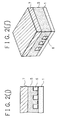
- FIGs. 2(a), 2(a'), 2(b), 2(b'), 2(c), 2(c'), 2(d), 2(d'), 2(e), 2(e'), 2(f), 2(f'), 2(g), 2(g'), 2(h), 2(h'), 2(i), 2(i'), 2(j), and 2(j') are schematic views for explaining a process for producing an ink jet head according to the present invention.
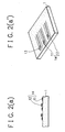
- FIG. 3(a) is a schematic cross-sectional view of a discharging outlet portion of an ink jet head produced in each of Examples 1 and 2 which will be later described.
- FIG. 3(b) is a schematic cross-sectional view of a discharging outlet portion of an ink jet head produced in each of Comparative Examples 1 and 2 which will be later described.
- FIG. 4 is a schematically exploded view illustrating an example of the constitution of a conventional ink jet head.
- FIG. 5 is a schematic diagram of an ink jet apparatus in which an ink jet head according to the present invention can be installed.
- the present inventors made extensive studies in order to solve the foregoing problems in the prior art and in order to attain the foregoing objects.
- the present inventors prepared a plurality of conventional ink jet heads having a plurality of ink flow path walls formed of a resin composition comprising epoxy resin incorporated with a flexibilizer.
- any of the ink jet heads used was found to perform desirable printing over a long period of time.
- any of the ink jet heads used was found to sometimes provide prints accompanied by defects after the repeated use over a long period of time.
- observation was made through its discharging outlet side.
- the epoxy resin as the main constituent of the resin composition by which the ink flow path walls are constituted excels in ink resistance. Therefore, it is considered that the debonding of the ink flow path walls from the substrate is chiefly due to the flexibilizer contained in the resin composition.
- the present inventors made studies in order to find out an appropriate material capable of serving to reduce the elasticity modulus of the epoxy resin in the liquid state at room temperature which is conventionally used as the constituent material of the ink flow path walls in a conventional ink jet head, instead of the flexibilizer.
- the present invention has been accomplished based on these findings.
- the present invention provides an ink jet head including: a plurality of discharging outlets serving to discharge ink (hereinafter referred to as ink discharging outlet); a substrate for an ink jet recording head including a plurality of energy generating elements capable of generating an energy for discharging ink from said ink discharging outlets and wirings electrically connected to said energy ganerating elements; and a plurality of ink pathways each having an ink flow path wall of forming one of the ink pathways by joining to said substrate, characterized in that each of the ink flow path walls is constituted by (a) a specific epoxy resin composition comprising (b) a hardening epoxy resin in the liquid state at room temperature as a main component and (c) a siloxane bond possessing epoxy resin (that is, an epoxy resin with a diepoxide structure having a siloxane bond) in a given amount.
- the epoxy resin composition will be hereinafter occasionally referred to as "ink flow path wall-forming material".
- the ink flow path walls formed of the above described specific resin composition (a) are apparently surpassing the conventional ink flow path walls comprised of the epoxy resin incorporated with the flexibilizer especially in terms of the resistance to not only the ordinary ink but also highly alkaline ink. Further, the specific resin composition (a) enables to form highly precise ink pathways which are surpassing those ink pathways formed of the epoxy resin incorporated with the flexibilizer.
- the use of the siloxane bond possessing epoxy resin (c) in an amount equivalent to that of the flexibilizer incorporated into the epoxy resin effects to reduce the viscosity of the ink flow path wall-forming material (that is, the resin composition (a)) to a value corresponding to 1/10 of that of the epoxy resin incorporated with the flexibilizer, and no air bubble is taken into the resin composition (a) as the ink flow path wall-forming material upon the application thereof at the time of forming ink flow path walls.
- This situation makes it possible to form highly precise ink flow path walls without conducting deaeration.
- the ink flow path wall-forming material according to the present invention comprise the foregoing specific resin composition (a) (comprising a hardening epoxy resin (b) in the liquid state at room temperature as a main component and a siloxane bond possessing epoxy resin (c)).
- the resin composition (a) contains a curing agent or/and a polymerization initiator. If necessary, the resin composition (a) may contain a silane coupling agent capable of improving the adhesion of the resin composition.
- the hardening epoxy resin (b) in the liquid state at room temperature as the main component of the resin composition (a) means a hardening epoxy resin having a viscosity of 10 to 100,000 cps at room temperature (25 °C).
- the hardening epoxy resin (b) can include hardening epoxy resins in the semisolid state at room temperature.
- any known hardening epoxy resins may be used as long as they have two or more epoxy groups in one molecule and are in the liquid state or the semisolid state at room temperature.
- these hardening epoxy resins in the viewpoint of the ink resistance, those having a molecular weight of 300 or more are the most desirable.
- hardening epoxy resin (b) are bisphenol A type epoxy resins, bisphenol F type epoxy resins, bisphenol AD type epoxy resins, bisphenol AF type epoxy resins, and novolak type epoxy resins. These resins may be used either singly or in combination of two or more of them
- the siloxane bond possessing epoxy resin (c) (that is, the epoxy resin with a diepoxide structure having a siloxane bond) used in the present invention may be epoxy resins obtained by a manner of reacting an appropriate compound having a Si-OH bond with epichlorohydrin in an alkaline aqueous solution or another manner of subjecting dimethyl polysiloxane having a Si-H group and a unsaturated epoxy compound such as acrylic glycidyl ether or vinylcyclohexane oxide to addition condensation in the presence of a platinum catalyst.
- epoxy resins obtained by a manner of reacting an appropriate compound having a Si-OH bond with epichlorohydrin in an alkaline aqueous solution or another manner of subjecting dimethyl polysiloxane having a Si-H group and a unsaturated epoxy compound such as acrylic glycidyl ether or vinylcyclohexane oxide to addition condensation in the presence of a platinum catalyst.
- siloxane bond possessing epoxy resins having an excessively high molecular weight are not usable in the present invention because they are relatively high in viscosity and are low in ink resistance.
- silane bond possessing epoxy resins having an excessively small molecular weight are not usable in the present invention because they are of a low boiling point and cannot be stably maintained in the liquid state at room temperature.
- siloxane bond possessing epoxy resin (c) desirably usable in the present invention are those having the following structural formula (I) or (II).
- each of R1 to R4 is an alkyl group of 1 to 4 carbon atoms, an alkenyl group of 2 to 6 carbon atoms, a phenyl group, or a substituted aromatic group wherein R1 to R4 may be the same or different one from the other;
- each of R5 and R6 is an alkylene group of 1 to 8 carbon atoms, or a phenylene group wherein R5 and R6 may be the same or different one from the other;
- n is an integer of 1 to 1000.
- a reaction vessel equipped with an agitator, a temperature gage, a dropping funnel and a device capable of condensing and separating an azeotropic mixture of epichlorohydrin and water and returning an epichlorohydrin phase to the reaction vessel.
- a given amount of 1,1,3,3-tetramethyl-1,3-diethoxydisilazane and a given amount of epichlorohydrin are introduced and the resultant mixture is circulated while stirring the mixture and while maintaining the mixture at a desired temperature.
- a given amount of an aqueous solution of NaOH is then dropwise added while maintaining the contents at a desired temperature.
- the resin composition (a) (comprising the hardening epoxy resin (b) in the liquid state at room temperature as a main component and the siloxane bond possessing epoxy resin (c)) as the ink flow path wall-forming material in the present invention is desired to contain the siloxane bond possessing epoxy resin (c) in an amount of 10 to 40 wt.% versus the total amount of the hardening epoxy resin (b) and the siloxane bond possessing epoxy resin (c).
- the ink flow path wall-forming material is such that has a relatively high elasticity modulus, and because of this, the ink flow path wall-forming material cannot sufficiently absorb a shrinkage stress caused upon forming ink flow path walls.
- a debonding is liable to occur at the interface between the ink flow path walls and the substrate when the ink jet head is continuously operated over a long period of time using the foregoing highly alkaline ink.
- any of the conventional curing agents usually used in the case of curing an epoxy resin is used.
- these curing agents amine series curing agents capable of causing curing at room temperature.
- Specific examples of such amine series curing agent are a commercially available modified aromatic amine series curing agent (trademark name: Fujicure FXK-830, produced by Fujikasei Kogyo Kabushiki Kaisha) and a commercially available modified aliphatic amine series curing agent (trademark name: Epomic Q614, produced by Mitsui Petrochemical Industries, Ltd.)
- the resin composition (a) (comprising the hardening epoxy resin (b) in the liquid state at room temperature as a main component and the siloxane bond possessing epoxy resin (c)) as the ink flow path wall-forming material in the present invention may be of thermohardening type or a photo-hardening type.
- the resin composition (a) may be made to be of a photo-hardening type by incorporating an appropriate photo-curing agent into the resin composition.
- cationic polymerized compounds which are not suffered from a polymerization hindrance due to oxygen, provide a slight cure shrinkage, provide an excellent adhesion and bonding property, and excel in heat resistance and resistance to chemicals.
- a preferred example of such cationic polymerized compound is a commercially available Adeka Optomer SP-170 (trademark name, produced by Asahi Denka Kogyo Kabushiki Kaisha).
- the resin composition (a) as the ink flow path wall-forming material is desired to contain a silane coupling agent.
- the resin composition (a) containing a silane coupling agent provides an improved adhesion and a reduced thixotropic property and is free of a problem of take-in of an air bubble upon applying onto a substrate. In addition, it exhibits a reduced viscosity.
- the silane coupling agent has a compatibility with a positive type photoresist, and because of this, the incorporation of an excessive amount of the silane coupling agent into the resin composition (a) shall be refrained.
- the composition (a) In addition to this, there is a tendency for the composition (a) to be decreased in terms of the ink resistance as the amount of the silane coupling agent to be incorporated into the resin composition (a) is increased. In view of this, it is desired for the amount of the silane coupling agent to be incorporated into the resin composition (a) to be in the range of 1 to 10 parts by weight versus the amount of the resin composition (a).
- silane coupling agent it is desired to use epoxy series silane coupling agents in the viewpoint of their compatibility with the resin composition (a).
- resin composition (a) contains an amine series thermohardening agent, it is desired to use an amine series silane coupling agent.
- FIGs. 2(a) through 2(j') are schematic views for explaining a process for producing an ink jet head according to the present invention.
- FIGs. 2(a), 2(b), 2(c), 2(d), 2(e), 2(f), 2(g), 2(h), 2(i), and 2(j) are schematic views of products obtained in respective steps in the production of an ink jet head when viewed from the discharging outlet side.
- FIGs. 2(a'), 2(b'), 2(c'), 2(d'), 2(e'), 2(f'), 2(g'), 2(h'), 2(i'), and 2(j') are schematic slant views of the respective products shown in FIGs. 2(a) through 2(j).
- reference numeral 1 indicates a base member made of a material selected from the group consisting of silicon wafer, metals, glass, ceramics, and plastics.
- an energy generating element for generating an energy for discharging printing liquid such as an electrothermal converting element or piezoelectric element
- this energy generating element will be hereinafter referred to as liquid discharging energy generating element
- an electrothermal converting element or piezoelectric element such as an electrothermal converting element or piezoelectric element.
- FIGs. 2(a) and 2(a') reference numeral 14 indicates an electrothermal converting element disposed on the base member 1.
- the electrothermal converting element 14 may be formed by the conventional thin film-forming technique employed in the semiconductor field. Particularly, the formation of the electrothermal converting element may be conducted, for example, in the following manner.
- a heat generating resistor layer 11 comprised of, for example, HfB2, TaN, or Ta2O5 is formed on the base member 1 by means of the sputtering or CVD process, followed by forming an electrode layer 12 comprised of, for example, Al on the heat generating resistor layer 11 by means of the sputtering, CVD or evaporation process. Thereafter, only the electrode layer 12 is patterned into such an electrode pattern as shown in FIG. 2(a') by means of the photolithography technique. Then, the heat generating resistor layer 11 is patterned into such a pattern as shown in FIG. 2(a') by means of the photolithography technique. By this, the formation of the electrothermal converting element 14 is completed.
- an exposed portion of the heat generating resistor layer 11 which is not covered by the electrode layer 12 corresponds an exothermic portion (a heat generating portion) 13.
- the liquid discharging energy generating element serves to generate an energy for discharging ink droplets thereby performing printing.
- the electrothermal converting element serves to heat ink present in the vicinity thereof to cause a state change of volume expansion for the ink, resulting in discharging ink.
- the piezoelectric element is used as the liquid discharging energy generating element
- ink discharging is conducted by virtue of a mechanical vibration caused by the piezoelectric element.
- wirings are electrically connected to any of these discharging energy generating elements (not shown in the figures).
- various functional layers including a protective layer are usually disposed thereon. In the present invention, these functional layers may be disposed.
- a photosensitive resin layer 2 comprised of a positive type photoresist is disposed on the base member 1 so as to cover the liquid discharging energy generating elements disposed on the base member 1 (see, FIGs. 2(b) and 2(b')).
- This step shown in FIGs. 2(b) and 2(b') will be hereinafter referred to as second step.
- the photosensitive resin layer 2 is formed of a positive type photoresist capable of being resolved and removed in a later treatment.
- a positive type photoresist capable of being resolved and removed in a later treatment.
- Specific examples of such photoresist are naphthoquinone series positive type photoresists, positive type photoresists of the chemical amplification type, and positive type photoresists of the backbone chain decomposition type.
- the formation of the photosensitive resin layer 2 may be conducted by means of the spin coating or roll coating technique. Other than this, it may be conducted by a manner of providing a dry film of any of the foregoing positive type photoresists and laminating the dry film on the base member 1.
- a third step (see, FIGs. 2(c) and 2(c')), the photosensitive resin layer side of the stacked body obtained in the second step is subjected to light exposure through a patterning mask 3 for forming ink pathway-forming portions.
- FIGs. 2(d) and 2(d') are schematic views illustration the resultant obtained in this step in which portions 2' of the photosensitive resin layer 2 have been solubilized as a result of the light exposure.
- a fourth step the light exposed portions 2' of the photosensitive resin layer 2 are subjected to development with an appropriate solvent such an alkali solution whereby forming a solid layer 4 (that is, a resist pattern) which serves to form ink pathways.
- the shapes of the ink pathways may be properly designed as desired by using, as the patterning mask 3, a patterning mask having a desired pattern capable of contributing to the formation such ink pathways.
- the resulting solid layer eventually becomes to have a pattern capable of providing such ink pathways having a desired shape.
- three liquid discharging energy generating elements there are described three liquid discharging energy generating elements. Therefore, three ink discharging outlets are disposed to correspond the respective liquid discharging energy generating elements so that an ink droplet can be discharged from each of the ink discharging outlets. Further, there are described three ink pathways each corresponding to one of the three ink discharging outlets. The three ink pathways are communicated with a common ink chamber such that ink can be supplied from the common ink chamber to each of the three ink pathways.
- the positive type resist constituting the solid layer is liable to produce nitrogen gas when it is reacted with light irradiated Therefore, when an ink flow path wall-forming material 5 (see, FIGs. 2(g) and 2(g')) is disposed to cover the solid layer 4 without conducting any treatment for the solid layer, a problem will be sometimes occurred in that gas is taken into the ink flow path wall-forming material to result in deforming the shapes of ink pathways to be formed. In order to prevent occurrence of this problem, after the entire of the solid layer has been subjected to light exposure, it is desired for the solid layer to be subjected to deaeration treatment.
- a hardening epoxy resin composition comprising a hardening epoxy resin in the liquid state at room temperature as a main component and an epoxy resin with a diepoxide structure having a siloxane bond (that is, the foregoing resin composition (a)) as the ink flow path wall-forming material 5 is applied onto the base member 1 so as to entirely cover the solid layer 4 formed on the base member by means of a dispenser or the like.
- the ink flow path wall-forming material 5 is subjected to heat treatment or light exposure treatment to harden the ink flow path forming material. Thereafter, the solid layer 4 is resolved and removed using an organic solvent such as halogen-containing hydrocarbon, ketone, ester, or alcohol or an aqueous alkaline solution of sodium hydroxide or potassium hydroxide to thereby form ink pathways and a common ink chamber in communication with any of these ink pathways. Thus, the production of an ink jet head is completed.
- an organic solvent such as halogen-containing hydrocarbon, ketone, ester, or alcohol or an aqueous alkaline solution of sodium hydroxide or potassium hydroxide
- FIG. 5 is an appearance perspective view illustrating an example of an ink jet apparatus (IJA) in which an ink jet head according to the present invention is installed as an ink jet head cartridge (IJC).
- reference numeral 20 indicates an ink jet head cartridge (IJC) provided with nozzle groups capable of discharging ink to the printing face of a printing sheet transported onto a platen 24.
- Reference numeral 16 indicates carriage (HC) which serves to hold the IJC 20.
- the carriage HC is connected to a part of driving belt 18 capable of transmitting a driving force such that it can be slidably moved together with two guide shafts 19A and 19B arranged in parallel with each other. By this, the IJC 20 is allowed to move back and forth along the entire of the printing sheet.
- Reference numeral 26 indicates a head restoring device which is disposed at one end of the moving passage of the IJC 20, specifically, at the position opposite the home position.
- the head restoring device 26 is operated by virtue of a driving force transmitted through a driving mechanism 23 from a motor 22, whereby capping the IJC 20.
- the discharge restoration treatment of removing adhesive ink in the nozzles is conducted by way of ink sucking by means of an appropriate sucking means disposed in the head restoring device 26 or by way of ink pressure transportation by means of an appropriate pressurizing means whereby forcibly discharging the ink through the discharging outlets.
- the IJC 20 is protected by capping it.
- Reference numeral 30 indicates a cleaning blade comprising a wiping member made of a silicon rubber which is arranged at a side face of the head restoring device 26.
- the cleaning blade 30 is supported by a blade supporting member 30A in a cantilever-like state.
- the cleaning blade 30 is operated by virtue of a driving force transmitted through the driving mechanism 23 from the motor 22, wherein the cleaning blade 30 is made capable of contacting with the discharging outlet face of the IJC 20.
- the cleaning blade 30 is projected into the moving passage of the IJC 20 timely with the printing performance of the IJC 20 or after the discharge restoration treatment using the head restoring device 26 having been completed, to thereby remove dew drops, wettings, dirts, and the like deposited on the discharging outlet face of the IJC 20.
- the present invention provides prominent effects in an ink jet head or an ink jet apparatus, especially of the system in which printing is conducted by discharging utilizing thermal energy.
- the representative constitution and the principle it is desired to adopt such fundamental principle as disclosed, for example, in U.S. Pat. No. 4,723,129 or U.S. Pat. No. 4,740,796.
- this ink jet system is capable of applying ether the so-called on-demand type or the continuous type, it is particularly effective in the case of the on-demand type because, by applying at least one driving for providing a rapid temperature rise exceeding nucleate boiling in response to printing information to an electrothermal converting element disposed for a sheet on which printing liquid (ink) is to be held or for a liquid pathway, the electrothermal converting element generates thermal energy to cause film boiling on a heat acting face of the ink jet head and as a result, a bubble can be formed in the printing liquid (ink) in a one-by-one corresponding relationship to such driving signal.
- the printing liquid (ink) is discharged through a discharging outlet to form at least one droplet. It is more desirable to make the driving signal to be of a pulse shape, since in this case, growth and contraction of a bubble take place instantly and because of this, there can be attained discharging of the printing liquid (ink) excelling particularly in responsibility.
- driving signal of pulse shape such driving signal as disclosed in U.S. Pat. No. 4,463,359 or U.S. Pat. No. 4,345,262 is suitable. Additionally, in the case where those conditions disclosed in U.S. Pat. No. 4,313,124, which relates to the invention concerning the rate of temperature rise at the heat acting face, are adopted, further improved printing can be conducted.
- the present invention includes, other than those constitutions of the discharging outlets, liquid pathways and electrothermal converting elements in combination (linear liquid flow pathway or perpendicular liquid flow pathway) which are disclosed in the above mentioned patent documents, the constitutions using such constitution in which a heat acting portion is disposed in a curved region as disclosed in U.S. Pat. No. 4,558,333 or U.S. Pat No. 4,459,600.
- the present invention may effectively take a constitution based on the constitution in which a slit common to a plurality of electrothermal converting elements is used as a discharging portion of the electrothermal converting elements, which is disclosed in Japanese Unexamined Patent Publication No. 123670/1984 or another constitution in which an opening for absorbing a pressure wave of thermal energy is made to be corresponding to a discharging portion, which is disclosed in Japanese Unexamined Patent Publication No. 138461/1984.
- the present invention is effective in the case of a full-line type ink jet head having a length corresponding to the maximum width of a printing medium on which printing can be performed.
- This full-line type ink jet head may be of such constitution in which those ink jet heads disclosed in the above mentioned patent documents are combined or such constitution in which they are integrated into a full-line head.
- the present invention is effective also in the case of an ink jet head of the exchangeable chip type wherein electric connection to an apparatus body or supply of ink from the apparatus body is enabled when it is mounted on the apparatus body or in the case of another ink jet head of the cartridge type wherein an ink tank is integrally disposed on the ink jet head itself.
- preparatory auxiliary means to an ink jet apparatus according to the present invention in view of further stabilizing the ink jet apparatus.
- preliminary heating means including an electrothermal converting element or a separate heating element or a combination of these and to employ a preparatory discharging mode in which discharging is conducted separately from printing are also effective in order to achieve stable printing.
- the present invention is extremely effective not only in an ink jet apparatus which as, as the printing mode, a printing mode of a main color such as black but also in an ink jet apparatus which includes a plurality of different colors or at least one of full-colors by color mixture, in which a ink jet head is integrally constituted or a plurality of ink jet heads are combined.
- inks having a property of being liquefied, for the first time with thermal energy, such that such ink can be liquefied and discharged in the liquid state upon the application of thermal energy depending upon a printing signal or other ink that can start its solidification beforehand at the time of its arrival at a printing member in order to prevent the temperature of the ink jet head from raising due to thermal energy purposely used as the energy for a state change of ink from solid state to liquid state or in order to prevent ink from being vaporized by solidifying the ink in a state of being allowed to stand.
- these inks they can be used in such a manner as disclosed in Japanese Unexamined Patent Publication No.
- the present inventors conducted experimental studies in order to find out a desirable ink flow path wall-forming material having a desired elasticity modulus and an excellent ink resistance.
- epoxy resin composition (a) comprising (b) a hardening epoxy resin in the liquid state at room temperature as a main component and (c) a siloxane bond possessing epoxy resin (that is, an epoxy resin with a diepoxide structure having a siloxane bond) which has the advantages of the hardening epoxy resin and a desired elasticity modulus and which exhibits an excellent ink resistance which was developed by the present inventors, experimental studied were conducted of whether or not the epoxy resin composition (a) is effectively usable as the ink flow path wall-forming material so that the problems in the conventional ink jet head can be solved through the under described Experiments 1 to 22.
- bisphenol A type epoxy resin (trademark name: Epikote 828, produced by Yuka Shell Kabishiki Kaisha).
- This bisphenol A type epoxy resin in an amount of 75 parts by weight was well mixed with 25 parts by weight of 1,3-bis(3-glycidoxypropyl)tetramethyldisiloxane as the siloxane bond possessing epoxy resin (c).
- a main component 100 parts of weight of the main component was mixed with 50 parts by weight of a modified aromatic amine series curing agent comprising Fujicure FXK-830 (trademark name, produced by Fujikasei Kogyo Kabushiki Kaisha).
- sample A a specimen in the liquid state at room temperature
- bisphenol A type epoxy resin (trademark name: Epikote 828, produced by Yuka Shell Kabishiki Kaisha).
- This bisphenol A type epoxy resin in an amount of 75 parts by weight was well mixed with 25 parts by weight of 1,1,3,3-tetramethyl-1,3-diglycidyletherdisiloxane as the siloxane bond possessing epoxy resin (c).
- a main component 100 parts of weight of the main component was mixed with 28 parts by weight of a modified aliphatic amine series curing agent comprising Epomic Q614 (trademark name, produced by Mitsui Petrochemical Industries, Ltd.).
- bisphenol AD type epoxy resin (trademark name: Epomic R710, produced by Mitsui Petrochemical Industries, Ltd.).
- Epomic R710 1,3-bis(3-glycidoxypropyl)tetramethyldisiloxane as the siloxane bond possessing epoxy resin (c).
- Epomic Q614 (trademark name, produced by Mitsui Petrochemical Industries, Ltd.).
- bisphenol AD type epoxy resin (trademark name: Epomic R710, produced by Mitsui Petrochemical Industries, Ltd.).
- Epomic R710 produced by Mitsui Petrochemical Industries, Ltd.
- This bisphenol AD type epoxy resin in an amount of 90 parts by weight was well mixed with 10 parts by weight of 1,1,3,3-tetramethyl-1,3-diglycidyletherdisiloxane as the siloxane bond possessing epoxy resin (c).
- a main component 100 parts of weight of the main component was mixed with 50 parts by weight of a modified aromatic amine series curing agent comprising Fujicure FXK830 (trademark name, produced by Fujikasei Kabushiki Kaisha).
- bisphenol AD type epoxy resin (trademark name: Epomic R710, produced by Mitsui Petrochemical Industries, Ltd.).
- Epomic R710 produced by Mitsui Petrochemical Industries, Ltd.
- This bisphenol AD type epoxy resin in an amount of 95 parts by weight was well mixed with 5 parts by weight of 1,1,3,3-tetramethyl-1,3-diglycidyletherdisiloxane as the siloxane bond possessing epoxy resin (c).
- a main component 100 parts of weight of the main component was mixed with 28 parts by weight of a modified aliphatic amine series curing agent comprising Epomic Q614 (trademark name, produced by Mitsui Petrochemical Industries, Ltd.).
- bisphenol A type epoxy resin (trademark name: Epikote 828, produced by Yuka Shell Kabishiki Kaisha).
- This bisphenol A type epoxy resin in an amount of 75 parts by weight was cell mixed with 25 parts by weight of a flexibilizer Epolite 3002 (trademark name, produced by Kyoeiyushi Kabushiki Kaisha).
- a flexibilizer Epolite 3002 (trademark name, produced by Kyoeiyushi Kabushiki Kaisha).
- a main component 100 parts of weight of the main component was mixed with 50 parts by weight of a modified aromatic amine series curing agent comprising Fujicure FXK-830 (trademark name, produced by Fujikasei Kogyo Kabushiki Kaisha).
- bisphenol A type epoxy resin (trademark name: Epikote 828, produced by Yuka Shell Kabishiki Kaisha).
- This bisphenol A type epoxy resin in an amount of 75 parts by weight was well mixed with 25 parts by weight of 1,3-bis(3-glycidoxypropyl)tetramethyldisiloxane as the siloxane bond possessing epoxy resin (c).
- a main component 100 parts of weight of the main component was mixed with 1.5 parts by weight of a cationic ultraviolet-ray curing initiator Adeka Optomer SP-170 (trademark name, produced by Asahidenka Kogyo Kabushiki Kaisha).
- bisphenol AD type epoxy resin (trademark name: Epomic R710, produced by Mitsui Petrochemical Industries, Ltd.).
- Epomic R710 produced by Mitsui Petrochemical Industries, Ltd.
- This bisphenol AD type epoxy resin in an amount of 80 parts by weight was well mixed with 20 parts by weight of 1,1,3,3-tetramethyl-1,3-diglycidyletherdisiloxane as the siloxane bond possessing epoxy resin (c).
- a main component 100 parts of weight of the main component was mixed with 1.5 parts by weight of a cationic ultraviolet-ray curing initiator Adeka Optomer SP-170 (trademark name, produced by Asahidenka Kogyo Kabushiki Kaisha).
- bisphenol A type epoxy resin (trademark name: Epikote 828, produced by Yuka Shell Kabushiki Kaisha).
- This bisphenol A type epoxy resin in an amount of 95 parts by weight was well mixed with 5 parts by weight of 1,1,3,3-tetramethyl-1,3-diglycidyletherdisiloxane as the siloxane bond possessing epoxy resin (c).
- a main component 100 parts of weight of the main component was mixed with 1.5 parts by weight of a cationic ultraviolet-ray curing initiator Adeka Optomer SP-170 (trademark name, produced by Asahidenka Kogyo Kabushiki Kaisha).
- bisphenol AD type epoxy resin (trademark name: Epomic R710, produced by Mitsui Petrochemical Industries, Ltd.).
- Epomic R710 produced by Mitsui Petrochemical Industries, Ltd.
- This bisphenol AD type epoxy resin in an amount of 90 parts by weight was well mixed with 10 parts by weight of 1,3-bis(3-glycidoxypropyl)tetramethyldisiloxane as the siloxane bond possessing epoxy resin (c).
- a main component 100 parts of weight of the main component was mixed with 1.5 parts by weight of a cationic ultraviolet-ray curing initiator Adeka Optomer SP-170 (trademark name, produced by Asahidenka Kogyo Kabushiki Kaisha).
- Sample R a specimen in the liquid state at room temperature
- each sample there were provided two glass plates as a substrate. And on the surface of each substrate, a 100 um thick coat was formed by applying a specimen of each sample. Then, as for each of Samples A to N, preparatory hardening was conducted at room temperature, followed by conducting thermal hardening (thermosetting) at 130 °C for 2 hours. As for each of Samples O to V, irradiation of ultraviolet rays of 8.3J was firstly conducted, followed by conducting thermal hardening (thermosetting) at 130 °C for an hour.
- the two substrates each having hardened film thereon as for each of Samples A to V were treated as follows.
- the form retention means the mechanical strength of a material when it is used as a constituent of an ink jet head.
- the material is less than 60 kgf/mm2 in bending elasticity modulus, it can be said that the material is insufficient in terms of the mechanical strength and therefore, when ink flow path walls are formed using this material, the ink flow path walls are poor in form retention, and they are liable to be suffered from a damage.
- the hardened film formed of any of Samples E, J, M, Q and U obtained in Experiments 5, 10, 13, 17 and 21 causes a deponding when immersed in the ordinary ink and in the highly alkaline ink wherein it is peeled off from the substrate.
- the hardened film formed of any of Samples N and V obtained in Experiments 14 and 22 although it does not causes a debonding when immersed in the ordinary ink, when it is immersed in the highly alkaline ink, it causes a debonding wherein it is peeled off from the substrate.
- the hardened film formed of Sample F is substantially free of occurrence of a debonding when immersed in the ordinary ink and also in the highly alkaline ink, but when immersed in the highly alkaline ink, a slight removal is occurred between the hardened film and the substrate. As for the hardened film formed of each of the remaining samples, no debonding is occurred when immersed in the ordinary ink and also in the highly alkaline ink.
- the molded product obtained from each of Samples I and T obtained in Experiments 9 and 20 is less than 60 kgf/mm2 in bending elasticity modulus and thus, it is inferior in mechanical strength.
- the reason why the hardened film causes a debonding when immersed in the ordinary ink and also in the highly alkaline ink is considered due to a fact that because the main component is relatively high in elasticity modulus, specifically, the content of the hardening epoxy resin (b) in the main component is relatively high, a shrinkage stress generated upon the hardening cannot be sufficiently absorbed to result in causing such debonding wherein the hardened film is peeled off from the substrate.
- the reason why the hardened film causes a debonding when immersed in the highly alkaline ink is considered due to a fact that the flexibilizer is decomposed with the action of the highly alkaline ink to reduce the ink resistance of the hardened film whereby causing such debonding wherein the hardened film is peeled off from the substrate.
- each of Samples I and T obtained in Experiments 9 and 20 is inferior in mechanical strength, it is considered due to a fact that the content of the hardening epoxy resin (b) in the main component is relatively small and this makes the molded product to be inferior in mechanical strength.
- each of Samples I and T obtained in Experiments 9 and 20 takes a remarkably longer period of time upon the hardening in comparison with the hardening time in the case of each of other samples. Therefore, there cannot be attained a desired yield in the production of an ink jet head by using any of Samples I and T.
- the former sample is of a remarkably low viscosity corresponding to a value of about 1/13 of the viscosity of the latter sample (in which the conventional flexibilizer was used) and that the former sample is free of a problem of causing take-in of an air bubble upon the application thereon onto a substrate but the latter sample is not free of such problem.
- any of Samples A, B, C, D, F, G, H, K, L, O, P, R, and S (each comprising the foregoing resin composion (a) as the main component, said resin composition comprising the hardening epoxy resin (b) in the liquid state at room temperature and the diepoxide structure possessing epoxy resin (c)) obtained in Experiments 1-4, 6-8, 11-12, 15-16, and 18-19 belonging to the present invention is desirably usable as an ink flow path wall-forming material which enables to form high quality ink flow path walls free from occurrence of a debonding even in the case of using a highly alkaline ink, resulting in making it possible to efficiently produce a high quality ink jet head which ensures stable ink discharging.
- Samples A, B, O and P obtained in Experiments 1, 2, 15 and 16 are the most desirable in the total viewponts.
- silicon wafer as a base member.
- a 2000 ⁇ thick HfB2 layer as a heat generating resistor layer by means of the sputtering process, followed by forming, on the heat generating resistor layer, a 1 ⁇ m thick aluminum layer as an electrode layer by means of the electron beam evaporation process.
- the base member having the heat generating resistor layer and electrode layer formed thereon was subjected to patterning by means of the photolithography technique to form a plurality of electrothermal converting elements at 360 dpi corresponding to 128 nozzles.
- a positive type photoresist PMER AR-900 (trademark name, produced by Tokyo Ohkakogyo Kabushiki Kaisha) was applied in an amount to provide a thickness of 30 um when dried so as to entirely cover the electrothermal converting elements on the base member by means of the spin coating process, followed by conducting baking treatment at 90 °C for 40 minutes in an oven, whereby forming a resist layer.
- the resultant was subjected to light exposure using a nozzle patterning mask, followed by subjecting to development and then to rinsing, whereby forming a patterned solid layer having a nozzle pattern with a pitch of 40 ⁇ m.
- the resin composition comprising Sample A obtained in Experiment 1 was applied onto the base member so as to entirely cover the solid layer, followed by subjecting to preliminary hardening treatment at 25 °C for 24 hours and then to thermal hardening treatment (thermosetting treatment) at 100 °C for 2 hours.
- the resultant was immersed in an aqueous solution of sodium hydroxide with a 3 wt.% content, wherein the solid layer having the nozzle pattern was removed. By this, an ink jet head was obtained. In this way, there were prepared a plurality of ink jet heads.
- Each of the resultant ink jet heads was subjected to continuous printing test, wherein printing was continuously conducted for 1000 hours using highly alkaline ink of pH 10.7 (composed of 10.0 wt.% of GLY, 5.0 wt.% of urea, 5.0 wt.% of IPA, 0.4 wt.% of lithium hydroxide, 0.5 wt.% of ammonium sulfate, and 79.9 Wt.% of water).
- pH 10.7 composed of 10.0 wt.% of GLY, 5.0 wt.% of urea, 5.0 wt.% of IPA, 0.4 wt.% of lithium hydroxide, 0.5 wt.% of ammonium sulfate, and 79.9 Wt.% of water.
- any of the ink jet heads was found to conduct desirable printing stably and continuously over the period of 1000 hours without causing any defective ink discharge and any defective print.
- observation was conducted its portions in the vicinity of the discharging outlets. As a result, it was found that the interface between the base member (that is, the substrate for an ink jet head) and the ink flow path walls is maintained in a desirably bonded state with no removal as shown in FIG. 3(a).
- a silicon wafer as a base member.
- a 2000 ⁇ thick HfB2 layer as a heat generating resistor layer by means of the sputtering process, followed by forming, on the heat generating resistor layer, a 1 ⁇ m thick aluminum layer as an electrode layer by means of the electron beam evaporation process.
- the base member having the heat generating resistor layer and electrode layer formed thereon was subjected to patterning by means of the photolithography technique to form a plurality of electrothermal converting elements at 360 dpi corresponding to 128 nozzles.
- a positive type photoresist PMER AR-900 (trademark name, produced by Tokyo Ohkakogyo Kabushiki Kaisha) was applied in an amount to provide a thickness of 30 um when dried so as to entirely cover the electrothermal converting elements on the base member by means of the spin coating process, followed by conducting baking treatment at 90 °C for 40 minutes in an oven, whereby forming a resist layer.
- the resultant was subjected to light exposure using a nozzle patterning mask, followed by subjecting to development and then to rinsing, whereby forming a patterned solid layer having a nozzle pattern with a pitch of 40 ⁇ m.
- the resin composition comprising Sample P obtained in Experiment 16 was applied onto the base member so as to entirely cover the solid layer, followed by subjecting to irradiation of ultraviolet rays of 8.3J and then to thermal hardening treatment (thermosetting treatment) at 130 °C for an hour.
- the resultant was immersed in an aqueous solution of sodium hydroxide with 3 wt.% content, wherein the solid layer having the nozzle pattern was removed. By this, an ink jet head was obtained. In this way, there were prepared a plurality of Ink jet heads.
- Each of the resultant ink jet heads was subjected to continuous printing test, wherein printing was continuously conducted for 1000 hours using highly alkaline ink of pH 10.7 (composed of 10.0 wt.% of GLY, 5.0 wt.% of urea, 5.0 wt.% of IPA, 0.4 wt.% of lithium hydroxide, 0.5 wt.% of ammonium sulfate, and 79.9 wt.% of water).
- any of the ink jet heads was found to conduct desirable printing stably and continuously over the period of 1000 hours without causing any defective ink discharge and any defective print.
- observation was conducted its portions in the vicinity of the discharging outlets. As a result, it was found that the interface between the base member (that is, the substrate for an ink jet head) and the ink flow path walls is maintained in a desirably bonded state with no removal as shown in FIG. 3(a).
- Example 1 The procedures of Example 1 were repeated, except that Sample M obtained in Experiment 13 was used as the ink flow path wall-forming material for an ink jet head, to thereby obtain a plurality of comparative ink jet heads.
- Each of the resultant comparative ink jet heads was subjected to continuous printing test, wherein printing was continuously conducted for 1000 hours using highly alkaline ink of pH 10.7 (composed of 10.0 wt.% of GLY, 5.0 wt.% of urea, 5.0 wt.% of IPA, 0.4 wt.% of lithium hydroxide, 0.5 wt.% of ammonium sulfate, and 79.9 wt.% of water).
- any of the comparative ink jet heads was found to often cause non-ink discharging and provision of defective prints.
- observation was conducted its portions in the vicinity of the discharging outlets. As a result, it was found that the ink flow path walls are debonded from the base member (that is, the substrate for an ink jet head) as shown in FIG. 3(b).
- Example 1 The procedures of Example 1 were repeated, except that Sample N obtained in Experiment 14 was used as the ink flow path wall-forming material for an ink jet head, to thereby obtain a plurality of comparative ink jet heads.
- Each of the resultant comparative ink jet heads was subjected to continuous printing test, wherein printing was continuously conducted for 1000 hours using highly alkaline ink of pH 10.7 (composed of 10.0 wt.% of GLY, 5.0 wt.% of urea, 5.0 wt.% of IPA, 0.4 wt.% of lithium hydroxide, 0.5 wt.% of ammonium sulfate, and 79.9 wt.% of water).
- any of the comparative ink jet heads was found to often cause non-ink discharging and provision of defective prints.
- observation was conducted its portions in the vicinity of the discharging outlets. As a result, it was found that the ink flow path walls are debonded from the base member (that is, the substrate for an ink jet head) as shown in FIG. 3(b).
- the foregoing resin composition (a) according to the present invention (comprising the foregoing hardening epoxy resin (b) in the liquid state at room temperature as a main component and the foregoing specific siloxane bond possessing epoxy resin (c)) enables to form high quality ink flow path walls for an ink jet head which are free from occurrence of a debonding from the substrate even in the case of using highly alkaline ink and that an ink jet head having the high quality ink flow path walls excels in ink discharging performance wherein stable ink discharging can be continuously conducted over a long period of time to continuously provide high quality prints even in the case where highly alkaline ink is used.
Landscapes
- Engineering & Computer Science (AREA)
- Manufacturing & Machinery (AREA)
- Chemical & Material Sciences (AREA)
- Health & Medical Sciences (AREA)
- Chemical Kinetics & Catalysis (AREA)
- Medicinal Chemistry (AREA)
- Polymers & Plastics (AREA)
- Organic Chemistry (AREA)
- Particle Formation And Scattering Control In Inkjet Printers (AREA)
Applications Claiming Priority (6)
| Application Number | Priority Date | Filing Date | Title |
|---|---|---|---|
| JP296220/93 | 1993-11-26 | ||
| JP29622093 | 1993-11-26 | ||
| JP29622093 | 1993-11-26 | ||
| JP29131294 | 1994-11-25 | ||
| JP291312/94 | 1994-11-25 | ||
| JP29131294A JP3397478B2 (ja) | 1993-11-26 | 1994-11-25 | インクジェットヘッド及び該インクジェットヘッドの製造方法及びインクジェット装置 |
Publications (2)
| Publication Number | Publication Date |
|---|---|
| EP0658430A1 true EP0658430A1 (fr) | 1995-06-21 |
| EP0658430B1 EP0658430B1 (fr) | 2002-05-08 |
Family
ID=26558489
Family Applications (1)
| Application Number | Title | Priority Date | Filing Date |
|---|---|---|---|
| EP94118704A Expired - Lifetime EP0658430B1 (fr) | 1993-11-26 | 1994-11-28 | Tête d'impresssion à jet d'encre ne présentant pas de détachement entre un substrat et les canaux d'éncoulement de l'encre formés sur ce substrat. |
Country Status (4)
| Country | Link |
|---|---|
| US (1) | US5663752A (fr) |
| EP (1) | EP0658430B1 (fr) |
| JP (1) | JP3397478B2 (fr) |
| DE (1) | DE69430565T2 (fr) |
Cited By (3)
| Publication number | Priority date | Publication date | Assignee | Title |
|---|---|---|---|---|
| EP0816095A1 (fr) * | 1996-06-28 | 1998-01-07 | Fraunhofer-Gesellschaft Zur Förderung Der Angewandten Forschung E.V. | Tête d'impression par jet d'encre à base de composés organosiliciques |
| EP0749043A3 (fr) * | 1995-06-14 | 1998-05-27 | Canon Kabushiki Kaisha | Procédé pour la fabrication d'une tête d'imprimante à jet d'encre |
| US6312085B1 (en) | 1997-06-26 | 2001-11-06 | Pelikan Produktions Ag | Ink jet printing head with elements made of organosilicic compounds |
Families Citing this family (34)
| Publication number | Priority date | Publication date | Assignee | Title |
|---|---|---|---|---|
| EP0779337B1 (fr) * | 1995-06-13 | 2001-10-24 | Canon Kabushiki Kaisha | Composition de resine epoxyde a base de fluor tres soluble dans des solvants |
| US6391140B1 (en) | 1998-07-10 | 2002-05-21 | Lexmark International, Inc. | Adhesive material with flexibility modifiers |
| JP3595743B2 (ja) * | 1998-10-27 | 2004-12-02 | キヤノン株式会社 | インクタンク、及び、そのインクタンクを含むカートリッジ、及び、そのカートリッジを用いる記録装置 |
| EP1085031B1 (fr) * | 1999-09-20 | 2004-11-17 | Canon Kabushiki Kaisha | Composition de résine d'époxy contenant d'alkylsiloxane, utilisation comme agent de modification d'une surface, tête d'enregistrement à jet de liquide et appareil d'enregistrement à jet de liquide |
| US6444745B1 (en) | 2000-06-12 | 2002-09-03 | General Electric Company | Silicone polymer network compositions |
| JP4622103B2 (ja) * | 2001-01-12 | 2011-02-02 | パナソニック株式会社 | 流体噴射装置 |
| US6531540B1 (en) | 2001-05-16 | 2003-03-11 | General Electric Company | Polyether siloxane copolymer network compositions |
| US6538061B2 (en) * | 2001-05-16 | 2003-03-25 | General Electric Company | Cosmetic compositions using polyether siloxane copolymer network compositions |
| US7241835B2 (en) * | 2001-05-16 | 2007-07-10 | General Electric Company | Cosmetic compositions comprising silicone gels |
| US20030203978A1 (en) * | 2001-05-16 | 2003-10-30 | O'brien Michael Joseph | Cosmetic compositions comprising silicone gels comprising entrapped, occluded or encapsulated pigments |
| US20030095935A1 (en) * | 2001-11-16 | 2003-05-22 | General Electric Company | Transfer resistant cosmetic compositions comprising silicone gels |
| US6846520B2 (en) * | 2002-01-17 | 2005-01-25 | Canon Kabushiki Kaisha | Epoxy resin composition, surface treatment method, liquid-jet recording head and liquid-jet recording apparatus |
| US6992117B2 (en) * | 2002-01-17 | 2006-01-31 | Canon Kabushiki Kaisha | Epoxy resin composition, surface treatment method, liquid-jet recording head and liquid-jet recording apparatus |
| US6869541B2 (en) * | 2002-02-21 | 2005-03-22 | Canon Kabushiki Kaisha | Epoxy resin composition, surface treating method, ink-jet recording head, and ink-jet recording apparatus |
| US6773869B1 (en) * | 2003-04-24 | 2004-08-10 | Lexmark International, Inc. | Inkjet printhead nozzle plate |
| JP2005074747A (ja) * | 2003-08-29 | 2005-03-24 | Canon Inc | インクジェットヘッドの製造方法およびインクジェットヘッド |
| TWI295632B (en) | 2005-01-21 | 2008-04-11 | Canon Kk | Ink jet recording head, producing method therefor and composition for ink jet recording head |
| JP4812086B2 (ja) * | 2005-01-21 | 2011-11-09 | キヤノン株式会社 | インクジェット記録ヘッド、該記録ヘッドの製造方法、及びインクジェット記録ヘッド用組成物 |
| US7637013B2 (en) * | 2005-08-23 | 2009-12-29 | Canon Kabushiki Kaisha | Method of manufacturing ink jet recording head |
| JP4854464B2 (ja) * | 2005-10-20 | 2012-01-18 | キヤノン株式会社 | 液体吐出ヘッドおよびその製造方法 |
| EP1801142B1 (fr) * | 2005-12-16 | 2016-02-24 | Canon Kabushiki Kaisha | Composition de résine, produit de résine durcit et tête de décharge liquide |
| JP5173273B2 (ja) * | 2007-06-19 | 2013-04-03 | キヤノン株式会社 | インクジェットヘッド用封止剤、インクジェットヘッドおよびインクジェット記録装置 |
| JP2010274627A (ja) * | 2009-06-01 | 2010-12-09 | Canon Inc | インクジェットプリンター用インク接液熱可塑性エラストマー組成物 |
| JP5501167B2 (ja) | 2010-09-08 | 2014-05-21 | キヤノン株式会社 | インクジェットヘッドの製造方法 |
| JP5697406B2 (ja) | 2010-11-09 | 2015-04-08 | キヤノン株式会社 | 親水被膜の形成方法および親水被膜、ならびにインクジェット記録ヘッドの製造方法およびインクジェット記録ヘッド |
| JP5539169B2 (ja) | 2010-11-22 | 2014-07-02 | キヤノン株式会社 | インクジェット用弾性部材 |
| US8657413B2 (en) | 2011-01-18 | 2014-02-25 | Funai Electric Co., Ltd. | Die attach composition for silicon chip placement on a flat substrate having improved thixotropic properties |
| US8728715B2 (en) * | 2012-01-13 | 2014-05-20 | Funai Electric Co., Ltd. | Non-photosensitive siloxane coating for processing hydrophobic photoimageable nozzle plate |
| JP5858813B2 (ja) | 2012-02-06 | 2016-02-10 | キヤノン株式会社 | 液体吐出ヘッド及びその製造方法 |
| US9744119B2 (en) | 2014-12-16 | 2017-08-29 | Momentive Performance Materials Inc. | Cosmetic composition and method of preparation |
| US9801805B2 (en) | 2014-12-16 | 2017-10-31 | Momentive Performance Materials Inc. | Personal care composition comprising silicone network |
| US9498409B2 (en) | 2014-12-16 | 2016-11-22 | Momentive Performance Materials Inc. | Cosmetic skin covering sheets and their method of preparation |
| US20160166494A1 (en) | 2014-12-16 | 2016-06-16 | Momentive Performance Materials Inc. | Cosmetic composition and method of preparation |
| US9839602B2 (en) | 2014-12-16 | 2017-12-12 | Momentive Performance Materials Inc. | Personal care compositions containing crosslinked silicone polymer networks and their method of preparation |
Citations (5)
| Publication number | Priority date | Publication date | Assignee | Title |
|---|---|---|---|---|
| DE1594311A1 (de) * | 1964-08-31 | 1970-07-16 | Ver Volkseigener Betr E Hausha | Verfahren zum Verkleben von Glas und keramischen Erzeugnissen |
| US4688053A (en) * | 1985-07-13 | 1987-08-18 | Canon Kabushiki Kaisha | Liquid jet recording head having a layer of a resin composition curable with an active energy ray |
| EP0432795A1 (fr) * | 1989-12-15 | 1991-06-19 | Canon Kabushiki Kaisha | Composition de résine durcissable par rayons à haute énergie, tête à jet d'encre dont la paroi du conduit d'encre est formée à l'aide de cette composition, procédé de préparation de la tête, et appareil à jet d'encre muni de la tête |
| EP0543202A1 (fr) * | 1991-10-31 | 1993-05-26 | Canon Kabushiki Kaisha | Composition de polymère pour le moulage par transfert utilisé dans la fabrication d'une tête d'enregistrement à jet d'encre et tête d'enregistrement ainsi produite |
| EP0568249A2 (fr) * | 1992-04-28 | 1993-11-03 | Xerox Corporation | Revêtement hydrophobe pour la face frontale d'une tête d'impression dans une imprimante à jet d'encre |
Family Cites Families (13)
| Publication number | Priority date | Publication date | Assignee | Title |
|---|---|---|---|---|
| CA1127227A (fr) * | 1977-10-03 | 1982-07-06 | Ichiro Endo | Procede d'enregistrement a jet liquide et appareil d'enregistrement |
| JPS5936879B2 (ja) * | 1977-10-14 | 1984-09-06 | キヤノン株式会社 | 熱転写記録用媒体 |
| US4330787A (en) * | 1978-10-31 | 1982-05-18 | Canon Kabushiki Kaisha | Liquid jet recording device |
| US4345262A (en) * | 1979-02-19 | 1982-08-17 | Canon Kabushiki Kaisha | Ink jet recording method |
| US4463359A (en) * | 1979-04-02 | 1984-07-31 | Canon Kabushiki Kaisha | Droplet generating method and apparatus thereof |
| US4313124A (en) * | 1979-05-18 | 1982-01-26 | Canon Kabushiki Kaisha | Liquid jet recording process and liquid jet recording head |
| US4558333A (en) * | 1981-07-09 | 1985-12-10 | Canon Kabushiki Kaisha | Liquid jet recording head |
| JPS59123670A (ja) * | 1982-12-28 | 1984-07-17 | Canon Inc | インクジエツトヘツド |
| JPS59138461A (ja) * | 1983-01-28 | 1984-08-08 | Canon Inc | 液体噴射記録装置 |
| JPS6071260A (ja) * | 1983-09-28 | 1985-04-23 | Erumu:Kk | 記録装置 |
| JPH0645242B2 (ja) * | 1984-12-28 | 1994-06-15 | キヤノン株式会社 | 液体噴射記録ヘツドの製造方法 |
| JPH0639166B2 (ja) * | 1985-09-12 | 1994-05-25 | キヤノン株式会社 | 記録器具 |
| EP0491560B1 (fr) * | 1990-12-19 | 1997-10-01 | Canon Kabushiki Kaisha | Méthode de fabrication de tête d'enregistrement par émission de liquide |
-
1994
- 1994-11-25 JP JP29131294A patent/JP3397478B2/ja not_active Expired - Fee Related
- 1994-11-28 EP EP94118704A patent/EP0658430B1/fr not_active Expired - Lifetime
- 1994-11-28 DE DE69430565T patent/DE69430565T2/de not_active Expired - Fee Related
- 1994-11-28 US US08/348,255 patent/US5663752A/en not_active Expired - Fee Related
Patent Citations (5)
| Publication number | Priority date | Publication date | Assignee | Title |
|---|---|---|---|---|
| DE1594311A1 (de) * | 1964-08-31 | 1970-07-16 | Ver Volkseigener Betr E Hausha | Verfahren zum Verkleben von Glas und keramischen Erzeugnissen |
| US4688053A (en) * | 1985-07-13 | 1987-08-18 | Canon Kabushiki Kaisha | Liquid jet recording head having a layer of a resin composition curable with an active energy ray |
| EP0432795A1 (fr) * | 1989-12-15 | 1991-06-19 | Canon Kabushiki Kaisha | Composition de résine durcissable par rayons à haute énergie, tête à jet d'encre dont la paroi du conduit d'encre est formée à l'aide de cette composition, procédé de préparation de la tête, et appareil à jet d'encre muni de la tête |
| EP0543202A1 (fr) * | 1991-10-31 | 1993-05-26 | Canon Kabushiki Kaisha | Composition de polymère pour le moulage par transfert utilisé dans la fabrication d'une tête d'enregistrement à jet d'encre et tête d'enregistrement ainsi produite |
| EP0568249A2 (fr) * | 1992-04-28 | 1993-11-03 | Xerox Corporation | Revêtement hydrophobe pour la face frontale d'une tête d'impression dans une imprimante à jet d'encre |
Cited By (5)
| Publication number | Priority date | Publication date | Assignee | Title |
|---|---|---|---|---|
| EP0749043A3 (fr) * | 1995-06-14 | 1998-05-27 | Canon Kabushiki Kaisha | Procédé pour la fabrication d'une tête d'imprimante à jet d'encre |
| US5980026A (en) * | 1995-06-14 | 1999-11-09 | Canon Kabushiki Kaisha | Process for production of ink jet head |
| EP0816095A1 (fr) * | 1996-06-28 | 1998-01-07 | Fraunhofer-Gesellschaft Zur Förderung Der Angewandten Forschung E.V. | Tête d'impression par jet d'encre à base de composés organosiliciques |
| WO1998000296A1 (fr) * | 1996-06-28 | 1998-01-08 | Pelikan Produktions Ag | Tete d'impression a jet d'encre avec des elements constitues de composes organosiliciques |
| US6312085B1 (en) | 1997-06-26 | 2001-11-06 | Pelikan Produktions Ag | Ink jet printing head with elements made of organosilicic compounds |
Also Published As
| Publication number | Publication date |
|---|---|
| JPH07195700A (ja) | 1995-08-01 |
| JP3397478B2 (ja) | 2003-04-14 |
| US5663752A (en) | 1997-09-02 |
| EP0658430B1 (fr) | 2002-05-08 |
| DE69430565T2 (de) | 2002-10-10 |
| DE69430565D1 (de) | 2002-06-13 |
Similar Documents
| Publication | Publication Date | Title |
|---|---|---|
| EP0658430B1 (fr) | Tête d'impresssion à jet d'encre ne présentant pas de détachement entre un substrat et les canaux d'éncoulement de l'encre formés sur ce substrat. | |
| US4609427A (en) | Method for producing ink jet recording head | |
| EP0432795B1 (fr) | Composition de résine durcissable par rayons à haute énergie, tête à jet d'encre dont la paroi du conduit d'encre est formée à l'aide de cette composition, procédé de préparation de la tête, et appareil à jet d'encre muni de la tête | |
| EP0779337B1 (fr) | Composition de resine epoxyde a base de fluor tres soluble dans des solvants | |
| US7687552B2 (en) | Resin composition, resin cured product, and liquid discharge head | |
| KR100626782B1 (ko) | 에폭시 수지 조성물, 표면 처리 방법, 액체 분사 기록헤드 및 액체 분사 기록 장치 | |
| EP0942024B1 (fr) | Tete d'enrigistrement a jet d'encre et appareil d'enregistrement a jet d'encre contentant une composition de resine epoxyde contentant du fluor | |
| EP1329472B1 (fr) | Composition de résine époxyde , procédé de modification de surfaces, tête d'enregistrement à jet d'encre et appareil d'enregistrement à jet d'encre | |
| US8158336B2 (en) | Process for making a micro-fluid ejection head structure | |
| US8007990B2 (en) | Thick film layers and methods relating thereto | |
| US6586495B1 (en) | Alkylsiloxane-containing epoxy resin composition, surface modifying method using the same, ink-jet recording head and liquid-jet recording apparatus | |
| EP0942026A2 (fr) | Composition de résine époxyde contenant du fluor, procédé de modification de surfaces, tête d'enregistrement à jet d'encre et appareil d'enregistrement à jet d'encre le contenant | |
| CN100580556C (zh) | 光敏树脂组合物、使用该组合物的喷墨记录头以及制造该喷墨记录头的方法 | |
| EP0942025A2 (fr) | Composition de résine époxyde contenant du fluor, procédé de modification de surfaces, tête d'enregistrement à jet d'encre et appareil d'enregistrement à jet d'encre le contenant | |
| EP0677389B1 (fr) | Tete a jet d'encre et appareil a jet d'encre equipe de celle-ci | |
| JP4174124B2 (ja) | 含フッ素エポキシ樹脂組成物を用いた表面改質方法、インクジェット記録ヘッド、インクジェット記録装置 | |
| KR100564851B1 (ko) | 에폭시 수지 조성물, 표면 처리 방법, 액체 분사 기록헤드 및 액체 분사 기록 장치 | |
| EP1752296A2 (fr) | Méthode de fabrication d'une tête d'impression à jet de liquide | |
| JP2021115778A (ja) | 液体吐出ヘッド及び液体吐出ヘッドの製造方法 | |
| GB2145976A (en) | Ink jet head | |
| JP4812086B2 (ja) | インクジェット記録ヘッド、該記録ヘッドの製造方法、及びインクジェット記録ヘッド用組成物 | |
| JP2006159764A (ja) | インクジェットヘッド及びその製造方法 |
Legal Events
| Date | Code | Title | Description |
|---|---|---|---|
| PUAI | Public reference made under article 153(3) epc to a published international application that has entered the european phase |
Free format text: ORIGINAL CODE: 0009012 |
|
| 17P | Request for examination filed |
Effective date: 19941128 |
|
| AK | Designated contracting states |
Kind code of ref document: A1 Designated state(s): DE FR GB IT |
|
| 17Q | First examination report despatched |
Effective date: 19960416 |
|
| GRAG | Despatch of communication of intention to grant |
Free format text: ORIGINAL CODE: EPIDOS AGRA |
|
| GRAG | Despatch of communication of intention to grant |
Free format text: ORIGINAL CODE: EPIDOS AGRA |
|
| GRAG | Despatch of communication of intention to grant |
Free format text: ORIGINAL CODE: EPIDOS AGRA |
|
| GRAG | Despatch of communication of intention to grant |
Free format text: ORIGINAL CODE: EPIDOS AGRA |
|
| GRAG | Despatch of communication of intention to grant |
Free format text: ORIGINAL CODE: EPIDOS AGRA |
|
| GRAH | Despatch of communication of intention to grant a patent |
Free format text: ORIGINAL CODE: EPIDOS IGRA |
|
| GRAH | Despatch of communication of intention to grant a patent |
Free format text: ORIGINAL CODE: EPIDOS IGRA |
|
| REG | Reference to a national code |
Ref country code: GB Ref legal event code: IF02 |
|
| GRAA | (expected) grant |
Free format text: ORIGINAL CODE: 0009210 |
|
| AK | Designated contracting states |
Kind code of ref document: B1 Designated state(s): DE FR GB IT |
|
| REF | Corresponds to: |
Ref document number: 69430565 Country of ref document: DE Date of ref document: 20020613 |
|
| ET | Fr: translation filed | ||
| PLBE | No opposition filed within time limit |
Free format text: ORIGINAL CODE: 0009261 |
|
| STAA | Information on the status of an ep patent application or granted ep patent |
Free format text: STATUS: NO OPPOSITION FILED WITHIN TIME LIMIT |
|
| 26N | No opposition filed |
Effective date: 20030211 |
|
| PGFP | Annual fee paid to national office [announced via postgrant information from national office to epo] |
Ref country code: FR Payment date: 20041109 Year of fee payment: 11 |
|
| PGFP | Annual fee paid to national office [announced via postgrant information from national office to epo] |
Ref country code: GB Payment date: 20041124 Year of fee payment: 11 |
|
| PGFP | Annual fee paid to national office [announced via postgrant information from national office to epo] |
Ref country code: DE Payment date: 20041125 Year of fee payment: 11 |
|
| PG25 | Lapsed in a contracting state [announced via postgrant information from national office to epo] |
Ref country code: IT Free format text: LAPSE BECAUSE OF NON-PAYMENT OF DUE FEES Effective date: 20051128 Ref country code: GB Free format text: LAPSE BECAUSE OF NON-PAYMENT OF DUE FEES Effective date: 20051128 |
|
| PG25 | Lapsed in a contracting state [announced via postgrant information from national office to epo] |
Ref country code: DE Free format text: LAPSE BECAUSE OF NON-PAYMENT OF DUE FEES Effective date: 20060601 |
|
| GBPC | Gb: european patent ceased through non-payment of renewal fee |
Effective date: 20051128 |
|
| PG25 | Lapsed in a contracting state [announced via postgrant information from national office to epo] |
Ref country code: FR Free format text: LAPSE BECAUSE OF NON-PAYMENT OF DUE FEES Effective date: 20060731 |
|
| REG | Reference to a national code |
Ref country code: FR Ref legal event code: ST Effective date: 20060731 |