EP0658432A2 - Abstandeinstellung des Aufzeichnungsträgers zur Verwendung in Druckern - Google Patents
Abstandeinstellung des Aufzeichnungsträgers zur Verwendung in Druckern Download PDFInfo
- Publication number
- EP0658432A2 EP0658432A2 EP94308739A EP94308739A EP0658432A2 EP 0658432 A2 EP0658432 A2 EP 0658432A2 EP 94308739 A EP94308739 A EP 94308739A EP 94308739 A EP94308739 A EP 94308739A EP 0658432 A2 EP0658432 A2 EP 0658432A2
- Authority
- EP
- European Patent Office
- Prior art keywords
- record media
- adjustment system
- path
- gap adjustment
- platen
- Prior art date
- Legal status (The legal status is an assumption and is not a legal conclusion. Google has not performed a legal analysis and makes no representation as to the accuracy of the status listed.)
- Granted
Links
- 230000033001 locomotion Effects 0.000 claims abstract description 17
- 238000001514 detection method Methods 0.000 claims abstract description 6
- 230000000694 effects Effects 0.000 claims abstract description 6
- 230000005484 gravity Effects 0.000 claims 1
- 238000007639 printing Methods 0.000 description 6
- 230000006978 adaptation Effects 0.000 description 2
- 238000000926 separation method Methods 0.000 description 2
- 239000000853 adhesive Substances 0.000 description 1
- 230000001070 adhesive effect Effects 0.000 description 1
- 230000003247 decreasing effect Effects 0.000 description 1
- 238000005516 engineering process Methods 0.000 description 1
- 238000007641 inkjet printing Methods 0.000 description 1
Images


Classifications
-
- B—PERFORMING OPERATIONS; TRANSPORTING
- B41—PRINTING; LINING MACHINES; TYPEWRITERS; STAMPS
- B41J—TYPEWRITERS; SELECTIVE PRINTING MECHANISMS, i.e. MECHANISMS PRINTING OTHERWISE THAN FROM A FORME; CORRECTION OF TYPOGRAPHICAL ERRORS
- B41J13/00—Devices or arrangements of selective printing mechanisms, e.g. ink-jet printers or thermal printers, specially adapted for supporting or handling copy material in short lengths, e.g. sheets
- B41J13/10—Sheet holders, retainers, movable guides, or stationary guides
- B41J13/12—Sheet holders, retainers, movable guides, or stationary guides specially adapted for small cards, envelopes, or the like, e.g. credit cards, cut visiting cards
-
- B—PERFORMING OPERATIONS; TRANSPORTING
- B41—PRINTING; LINING MACHINES; TYPEWRITERS; STAMPS
- B41J—TYPEWRITERS; SELECTIVE PRINTING MECHANISMS, i.e. MECHANISMS PRINTING OTHERWISE THAN FROM A FORME; CORRECTION OF TYPOGRAPHICAL ERRORS
- B41J11/00—Devices or arrangements of selective printing mechanisms, e.g. ink-jet printers or thermal printers, for supporting or handling copy material in sheet or web form
- B41J11/0045—Guides for printing material
- B41J11/005—Guides in the printing zone, e.g. guides for preventing contact of conveyed sheets with printhead
-
- B—PERFORMING OPERATIONS; TRANSPORTING
- B41—PRINTING; LINING MACHINES; TYPEWRITERS; STAMPS
- B41J—TYPEWRITERS; SELECTIVE PRINTING MECHANISMS, i.e. MECHANISMS PRINTING OTHERWISE THAN FROM A FORME; CORRECTION OF TYPOGRAPHICAL ERRORS
- B41J11/00—Devices or arrangements of selective printing mechanisms, e.g. ink-jet printers or thermal printers, for supporting or handling copy material in sheet or web form
- B41J11/20—Platen adjustments for varying the strength of impression, for a varying number of papers, for wear or for alignment, or for print gap adjustment
Definitions
- the present invention relates generally to printers and, more particularly, to an ink-jet printer employing a system which automatically adjusts the distance between the printer's platen and printhead.
- the system utilizes a stop mechanism which effects controlled positioning of the platen based on detected characteristics of the record media to be printed on.
- ink is deposited on record media via a traveling printhead which propels ink drops onto the record media as it passes thereacross.
- the record media is spaced from the printhead, the upper surface of the record media being held at a predetermined minimum distance from the printhead (D m ).
- Most printers set distance (D m ) using a platen which supports the record media, the platen generally being held in a fixed position relative to the printer's printhead. The distance between the printhead and platen is defined as the record media gap. This gap must accommodate the passage of record media therethrough without smearing, but spacing should be kept to a minimum so as to maximize the quality of print. Consequently, the platen is set at a distance from the printer's printhead which is approximately equal to the nominal record media thickness plus the desired printhead-to-medium spacing (D m ).
- a system for use in an ink-jet printer which selectively restricts movement of a printer's platen to effect adjustment of the printer's record media gap. Adjustment is automatically effected in response to detection of a predetermined record media characteristic which indicates a need to adjust the record media gap.
- the system is provided with a detector capable of recognizing the predetermined characteristic, and with a stop mechanism which acts in concert with the detector to effect the desired change. In its nominal configuration, the stop mechanism limits movement of the platen at a first position so as to define a first record media gap. However, upon detection of record media having the predetermined characteristic, the stop mechanism is automatically reconfigured so as to allow movement of the platen to a second position defining a second record media gap.
- the detector determines the need for gap adjustment based on the width of the record media, the detector being mounted at a predetermined lateral position along the record media path.
- the preferred detector includes a tab which nominally extends into the path of the record media, but which is movable from the path upon engagement by record media having a width within a predetermined range. Movement of the tab results in consequent movement of the stop mechanism, allowing the platen to move to its second predetermined position so as to establish the second predetermined record media gap.
- Fig. 1 is a top plan view of a printer which incorporates the invented record media gap adjustment system.
- Fig. 2 is a partial side view of the printer in Fig. 1, the system being arranged to illustrate passage of an envelope through the record media gap.
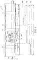
- Fig. 3 is a partial side view of the printer in Fig. 1, the system being arranged to illustrate passage of single-sheet media through the record media gap.
- Fig. 4 is a fragmentary enlargement of Fig. 2, showing the invented system in detail.
- Fig. 5 is a fragmentary enlargement of Fig. 3, showing the invented system in detail.
- the present invention relates to a system for use in an ink-jet printer, such system serving automatically to determine the thickness of record media which is to be processed by printer, and correspondingly to adjust the printer's record media gap.
- a system for use in an ink-jet printer such system serving automatically to determine the thickness of record media which is to be processed by printer, and correspondingly to adjust the printer's record media gap.
- the system is particularly well suited for use in an ink-jet printer, those familiar with printer technologies will appreciate that the system may similarly be employed in other style printers which require broadening or narrowing of the record media gap.
- printer 10 employs a record media handling mechanism 12, such mechanism being adapted to direct record media through a predetermined record media path (indicated generally at 32 in Figs. 2 and 3).
- mechanism 12 includes a plurality of spaced rollers 14, each of which is operatively connected to a motor-driven drive shaft 16.
- the mechanism also includes a pivot 18, the pivot being rotatable into various orientations so as to accommodate performance of various printer-related tasks.
- the pivot rotates between a pick-up orientation which accommodates receipt of record media, and a media-supporting orientation which accommodates printing thereon.
- a generally planar platen 18 a which supports record media during a print operation, the platen being movable with the pivot to define the printer's record media gap.
- printer 10 will be used in connection with a number of different record media types, the various types of record media making up a predetermined record media set. It is also contemplated that the different types of record media will exhibit different physical characteristics, and that some of the differences between record media types will require adaptation of the printer to compensate for a change in the type of record media used.
- the present invention addresses the need to adapt the printer based upon variations in record media thickness. This need arises due to conflicting problems of ink smearing and ink placement inaccuracies.
- Fig. 1 Several of the more common types of record media are depicted in Fig. 1, the illustrated types of record media including an envelope 20 a , a sheet of executive paper 20 b , and a sheet of A-size paper 20 c .
- the record media set would typically also include types of record media such as letter-size and legal-size sheets. It is thus evident that record media of two thickness characteristics are typically employed in an ink-jet printer, dividing the typical record media set into two subsets.
- the first subset includes multiple layer record media such as envelope 20 a
- the second subset includes single sheet media such as A-size paper 20 c .
- the path of record media path is defined with a transverse width which corresponds to the maximum width of the record media to be passed therethrough.
- the width of the record media path corresponds to the width of conventional A-size paper, but those skilled in the art will recognize that the path width need not be so limited. Most commonly, the record media path would be defined to coincide with the width of letter-size and legal-size sheets.
- Fig. 1 illustrates the flow of the various record media through the handling mechanism, each of the aforementioned record media types being shown in phantom as it is expelled from the printer's output port.
- the record media is justified to the right edge of the record media path, such justification preferably being accomplished by apparatus such as that described in co-pending U.S. Patent application Serial No. 07/954,540 entitled “Printer Paper Stack-handling Apparatus", which was filed on September 29, 1992, and which is owned commonly herewith.
- the disclosure of that patent application is incorporated herein by the present reference.
- each of the illustrative record media types will extend a known distance from the right edge of the media path (as shown in Fig. 1), such distance corresponding to the media's width.
- Envelope 20 a for example, extends a distance A from the path's right edge, such distance generally corresponding to a width of less than 5-inches across.
- Executive paper 20 b extends a distance B from the path's right edge, and
- A-size paper 20 c extends a distance C from the path's right edge.
- Distances B and C correspond to record media widths which fall within a range of between 5-inches and 8.5-inches across.
- the record media path thus may be considered to consist of two transverse regions, a first region which extends a distance A from the path's right edge, and a second region which extends from the path's first region to the path's left edge.
- first region which extends a distance A from the path's right edge
- second region which extends from the path's first region to the path's left edge.
- record media is directed along record media path 32 by the printer's drive rollers 14, and is guided by an arcuate record media guide 22.
- the guide is fixed to printer chassis 34 by suitable securement structure such as that indicated at 36.
- the rollers and guide are spaced to allow passage of the different types of record media therebetween, such space generally being defined in accordance with the maximum thickness of the record media to be passed therethrough. In the current embodiment the space between the rollers and record media guide is approximately equal to the thickness of envelope 20 a .
- a record media detector 24 which senses the presence or absence of record media at a predetermined transverse position along the record media path.
- the detector thus includes mounting bosses 24 a which are captured by hinge members 22 b so as to pivotally mount the detector to record media guide 22.
- the detector is mounted in a predetermined transverse position which accommodates active detection of record media within the path's second transverse region.
- the detector passively detects record media in the path's first transverse region by noting an absence of record media in the second transverse region.
- the presence of record media in the second transverse region during a print operation is indicative of relatively thin record media such as executive paper 20 b or A-size paper 20 c .
- the absence of record media in the second transverse region during a print operation is indicative of relatively thick record media such as envelope 20 a .
- Printhead 26 a is the ink-ejecting surface of an ink-jet pen 26.
- ink-jet pen 26 deposits ink on record media as the pen passes across the media in motions known as print swaths.
- the pen is carried through such motions by a pen carriage 28 which is movable along a transverse shaft 30.
- the vertical position of the printhead is fixed. The platen is moved with the pivot to adjust the record media gap.
- pivot 18 is rotatable about shaft 16, pivotal rotation of the pivot effecting corresponding movement of platen 18 a .
- Such movement results in adjustment of the record media gap, the platen being movable toward or away from the printer's printhead.
- the pivot is biased toward a clockwise rotational direction (as viewed in Figs. 2 through 5), such bias tending to urge the platen toward the printhead and thus into a position which accommodates printing.
- Bias is provided by conventional bias mechanism such as a yieldable spring (not shown).
- the pivot is shown in its nominal print orientation, such orientation being defined by a relationship between pivot 18 and record media detector 24.
- the detector includes a downwardly extending tab 40 which normally passes through an opening 22 a in record media guide 22.
- the tab engages a protuberance 42 on the pivot 18 upon rotation of the pivot in from a pick-up orientation to the printing orientation shown.
- the protuberance is engaged by a stop mechanism which is defined by surface 44 on detector 24.
- the stop mechanism engages a facing surface 42 a of protuberance 42, such engagement effectively defining the record media gap.
- the stop mechanism 44 halts rotation of pivot 18 when platen 18 a is in a first predetermined position so as to define a first predetermined record media gap.
- the record media gap is defined as the gap between the printhead and the platen, and nominally is arranged to accommodate passage of an envelope therethrough.
- the corresponding printhead-to-media spacing is illustrated in Fig. 4, such spacing being identified as S e . This distance must be sufficient to avoid smearing, but should not be so great as to significantly degrade the quality of print. In the preferred embodiment, S e is targeted at approximately 70-mils. This spacing is made difficult to determine, however, by the tendency of envelope layers to separate as the envelope leaves rollers 14.
- Separation of the envelope layers is caused by pinching of the record media as it leaves the paper guide. Pinching is effected by the edge 38 of paper guide 22. As indicated, separation of the envelope's layers compensates for the change in the angle of the platen upon rotation of pivot 18.
- the platen is at an angle ⁇ e when the pivot is in its nominal orientation (Fig. 4) but is at an angle ⁇ p when the platen is arranged to support single paper sheets (Fig. 5).
- the angle of the platen in Fig. 4 is approximately 5-degrees whereas the angle of the platen in Fig. 5 is only approximately 2-degrees.
- pivot 18 is provided with a catch 18 b , which is arranged to engage the printer's chassis 34 so as to limit clockwise rotation of the pivot to a predetermined maximum extent. Maximum rotation of the pivot corresponds to a minimum record media gap.
- Catch 18 a is thus positioned to engage the printer's chassis when the platen is in a second predetermined position such position being defined at an optimal distance from the printhead for printing on thin record media such as single paper sheets.
- S p Fig.5
- the detector includes a camming surface 40 a which is nominally positioned in the record media path.
- the camming surface extends into the second transverse region of the record media path, and is thus engaged by relatively thin media, but not by relatively thick media such as envelope 20 c .
- tab 40 will be pivoted from the record media path, removing stop mechanism 44 from the path of the pivot, and allowing the pivot to rotate into the orientation shown in Figs. 3 and 5. It will be appreciated that the camming surface must be engaged before the pivot is placed in its sheet-supporting orientation or the tab will be held in position by protuberance 42.
- the detector includes a body 46 which is of a weight accommodating gravity-directed bias of the detector toward its nominal configuration without damage to the record media which engages the tab.
- the camming surface is at an obtuse angle relative to the record media path, reducing the impact on the record media when it engages the tab.
- the record media will contact the camming surface on the detector, the paper being advanced forward with a force sufficient to slide the paper along the camming surface, thus raising the detector, as shown in Figs. 3 and 5.
- the tab will rest on the paper, the paper passing thereby with minimal opposition from the detector. The paper then will pass along the platen beneath the printer's printhead.
- the present invention is intended for use in an ink-jet printer, but may be used in virtually any style printer which requires adaptation of the printer's record media throat.
- the invented system may be used to detect various different types of record media, it being possible to adapt the system by changing the detector's transverse position or by employing multiple detectors.
Landscapes
- Handling Of Sheets (AREA)
Applications Claiming Priority (2)
| Application Number | Priority Date | Filing Date | Title |
|---|---|---|---|
| US166418 | 1993-12-14 | ||
| US08/166,418 US5366301A (en) | 1993-12-14 | 1993-12-14 | Record media gap adjustment system for use in printers |
Publications (3)
| Publication Number | Publication Date |
|---|---|
| EP0658432A2 true EP0658432A2 (de) | 1995-06-21 |
| EP0658432A3 EP0658432A3 (de) | 1995-12-13 |
| EP0658432B1 EP0658432B1 (de) | 1998-04-29 |
Family
ID=22603225
Family Applications (1)
| Application Number | Title | Priority Date | Filing Date |
|---|---|---|---|
| EP94308739A Expired - Lifetime EP0658432B1 (de) | 1993-12-14 | 1994-11-25 | Abstandeinstellung des Aufzeichnungsträgers zur Verwendung in Druckern |
Country Status (4)
| Country | Link |
|---|---|
| US (1) | US5366301A (de) |
| EP (1) | EP0658432B1 (de) |
| JP (1) | JP3476934B2 (de) |
| DE (1) | DE69409928T2 (de) |
Families Citing this family (28)
| Publication number | Priority date | Publication date | Assignee | Title |
|---|---|---|---|---|
| JP3397460B2 (ja) * | 1993-09-01 | 2003-04-14 | キヤノン株式会社 | インクジェット記録装置 |
| JP3437319B2 (ja) | 1994-04-05 | 2003-08-18 | キヤノン株式会社 | インクジェット記録装置およびインクジェット画像形成方法 |
| US5489160A (en) * | 1995-02-28 | 1996-02-06 | Hewlett-Packard Company | Print medium support mechanism for ink-jet printers |
| US5527123A (en) * | 1995-02-28 | 1996-06-18 | Hewlett-Packard Company | Media handling in an ink-jet printer |
| US5777635A (en) * | 1996-01-31 | 1998-07-07 | Lexmark International, Inc. | Automatic printhead-to-paper gap adjustment |
| KR200144532Y1 (ko) | 1996-03-08 | 1999-06-15 | 윤종용 | 잉크젯 프린터의 헤드 갭유지 구조 |
| US5683187A (en) * | 1996-06-18 | 1997-11-04 | Scitex Digital Printing, Inc. | Digital color press platen assembly with pivoting platen frame |
| KR100186611B1 (ko) * | 1996-06-26 | 1999-05-15 | 김광호 | 화상기록장치의 용지 두께감지장치와 그를 이용한 잉크젯트 기록헤드 자동 조정장치 및 방법 |
| US5730537A (en) * | 1997-03-13 | 1998-03-24 | Hewlett-Packard Company | Print media handling and ejection system |
| US6089773A (en) * | 1997-12-12 | 2000-07-18 | Lexmark International, Inc. | Print media feed system for an ink jet printer |
| JP3667096B2 (ja) * | 1998-06-30 | 2005-07-06 | キヤノン株式会社 | インクジェット記録装置及びインクジェット記録方法 |
| US7004652B2 (en) * | 2000-05-23 | 2006-02-28 | Silverbrook Research Pty Ltd | Printer for accommodating varying page thickness |
| US7213989B2 (en) * | 2000-05-23 | 2007-05-08 | Silverbrook Research Pty Ltd | Ink distribution structure for a printhead |
| US6988840B2 (en) * | 2000-05-23 | 2006-01-24 | Silverbrook Research Pty Ltd | Printhead chassis assembly |
| US6488422B1 (en) * | 2000-05-23 | 2002-12-03 | Silverbrook Research Pty Ltd | Paper thickness sensor in a printer |
| US6526658B1 (en) | 2000-05-23 | 2003-03-04 | Silverbrook Research Pty Ltd | Method of manufacture of an ink jet printhead having a moving nozzle with an externally arranged actuator |
| US6786658B2 (en) * | 2000-05-23 | 2004-09-07 | Silverbrook Research Pty. Ltd. | Printer for accommodating varying page thicknesses |
| DE60023952T2 (de) * | 2000-05-24 | 2006-12-07 | Silverbrook Research Pty. Ltd. | Sensor für die papierdicke in einem printer |
| US6796628B2 (en) * | 2002-11-07 | 2004-09-28 | Pitney Bowes Inc. | Contour correcting printer |
| US20060023023A1 (en) * | 2004-07-27 | 2006-02-02 | Mattern James M | Printing using traveling printheads |
| JP2006341936A (ja) * | 2005-06-07 | 2006-12-21 | Canon Inc | 記録装置及び記録方法 |
| JP5803785B2 (ja) | 2012-03-30 | 2015-11-04 | ブラザー工業株式会社 | インクジェットプリンタ |
| JP6032003B2 (ja) | 2012-03-30 | 2016-11-24 | ブラザー工業株式会社 | インクジェットプリンタ、インクジェットプリンタのギャップ情報取得方法、及び、液体吐出装置 |
| JP6115128B2 (ja) | 2012-03-30 | 2017-04-19 | ブラザー工業株式会社 | インクジェットプリンタのギャップ情報取得方法、インクジェットプリンタ、及び、液体吐出装置 |
| US8882215B2 (en) | 2012-03-30 | 2014-11-11 | Brother Kogyo Kabushiki Kaisha | Method and inkjet printer for acquiring gap information |
| JP6028565B2 (ja) | 2012-03-30 | 2016-11-16 | ブラザー工業株式会社 | インクジェットプリンタ、インクジェットプリンタのギャップ情報取得方法、及び、液体吐出装置 |
| DE102016208079A1 (de) * | 2015-09-16 | 2017-03-16 | Heidelberger Druckmaschinen Ag | Verfahren zur Kollisionsvermeidung, zur Anpassung des Abstandes und zur aktorischen Hubbewegung |
| US11890873B2 (en) | 2022-01-31 | 2024-02-06 | Xerox Corporation | System and method for compensating for vibrations in an inkjet printer |
Family Cites Families (17)
| Publication number | Priority date | Publication date | Assignee | Title |
|---|---|---|---|---|
| US4384794A (en) * | 1981-04-01 | 1983-05-24 | Tokyo Electric Co., Ltd. | Printer |
| US4575267A (en) * | 1984-04-23 | 1986-03-11 | Ncr Corporation | Record media thickness compensating mechanism |
| JPH0761725B2 (ja) * | 1986-08-29 | 1995-07-05 | エイ・ティ・アンド・ティ グローバル インフォメーション ソルーションズ インターナショナル インコーポレイテッド | プリンタ |
| US4780007A (en) * | 1987-06-29 | 1988-10-25 | Ncr Corporation | Record media thickness compensating mechanism |
| GB8722622D0 (en) * | 1987-09-25 | 1987-11-04 | Halo Retail Systems Ltd | Dot-matrix printers |
| US4810110A (en) * | 1987-09-28 | 1989-03-07 | Micro Peripherals, Inc. | Form thickness compensator with cutter |
| US4843338A (en) * | 1987-10-23 | 1989-06-27 | Hewlett-Packard Company | Ink-set printhead-to-paper referencing system |
| US5065169A (en) * | 1988-03-21 | 1991-11-12 | Hewlett-Packard Company | Device to assure paper flatness and pen-to-paper spacing during printing |
| US4932797A (en) * | 1988-06-17 | 1990-06-12 | Printronix, Inc. | Resettable locking platen gap adjustment mechanism |
| KR950000252B1 (ko) * | 1989-02-10 | 1995-01-12 | 오끼덴끼고오교 가부시끼가이샤 | 인자헤드갭 자동조정기구 |
| DE3913073A1 (de) * | 1989-04-21 | 1990-10-25 | Philips Patentverwaltung | Verfahren zur einstellung eines druckspaltes bei einem drucker |
| US5187497A (en) * | 1989-09-18 | 1993-02-16 | Canon Kabushiki Kaisha | Ink jet recording apparatus having gap adjustment between the recording head and recording medium |
| US5000594A (en) * | 1989-10-13 | 1991-03-19 | Hewlett-Packard Company | Printer with carriage-actuated clutch and paper-feed mechanism |
| US5156466A (en) * | 1989-10-18 | 1992-10-20 | Fujitsu Limited | Method and apparatus for adjusting the spacing between head and platen in an impact printer or the like |
| JP2541457Y2 (ja) * | 1990-08-31 | 1997-07-16 | アマノ株式会社 | 印字装置 |
| DE4041985A1 (de) * | 1990-12-21 | 1992-07-02 | Mannesmann Ag | Drucker, insbesondere matrixdrucker |
| US5108205A (en) * | 1991-03-04 | 1992-04-28 | International Business Machines Corp. | Dual lever paper gap adjustment mechanism |
-
1993
- 1993-12-14 US US08/166,418 patent/US5366301A/en not_active Expired - Lifetime
-
1994
- 1994-11-25 EP EP94308739A patent/EP0658432B1/de not_active Expired - Lifetime
- 1994-11-25 DE DE69409928T patent/DE69409928T2/de not_active Expired - Lifetime
- 1994-12-12 JP JP30799594A patent/JP3476934B2/ja not_active Expired - Fee Related
Also Published As
| Publication number | Publication date |
|---|---|
| DE69409928D1 (de) | 1998-06-04 |
| JP3476934B2 (ja) | 2003-12-10 |
| JPH07195770A (ja) | 1995-08-01 |
| DE69409928T2 (de) | 1998-08-13 |
| EP0658432A3 (de) | 1995-12-13 |
| US5366301A (en) | 1994-11-22 |
| EP0658432B1 (de) | 1998-04-29 |
Similar Documents
| Publication | Publication Date | Title |
|---|---|---|
| US5366301A (en) | Record media gap adjustment system for use in printers | |
| JP3119754B2 (ja) | 記録装置 | |
| JP4934488B2 (ja) | 記録装置 | |
| US5603493A (en) | System for use in handling media | |
| US7916359B2 (en) | Image forming apparatus | |
| US6435641B1 (en) | Media movement apparatus | |
| JP3397460B2 (ja) | インクジェット記録装置 | |
| EP2095967A1 (de) | Bildaufzeichnungsvorrichtung und -verfahren | |
| US6390703B1 (en) | Media handling system | |
| JPS60210475A (ja) | プリンタのオ−トカツトシ−ト給送装置 | |
| EP0104058B1 (de) | Aufzeichnungsträgerzufuhrvorrichtung für einen Drucker | |
| US6805508B2 (en) | Skew-correcting media delivery system and method | |
| JP3805174B2 (ja) | 記録媒体後端検出方法及び記録装置 | |
| US5538237A (en) | Sheet supplying apparatus | |
| EP0729842B1 (de) | Medientransport bei einem Tintenstrahldrucker | |
| GB2299973A (en) | Arrangement for discharging a recording medium from a printer | |
| US20060193670A1 (en) | Gap detector, liquid ejecting apparatus incorporating the same, and gap detecting method executed in the apparatus | |
| JPH01275090A (ja) | インクジェットプリンタ | |
| EP1690817A2 (de) | Zufuhrvorrichtung für Aufzeichnungsmedium und damit versehenes Flüssigkeitsausstossgerät oder Aufzeichnungsgerät | |
| JP3741588B2 (ja) | インクジェット画像形成装置 | |
| JP3466820B2 (ja) | 記録媒体搬送装置 | |
| JP3022265B2 (ja) | プリンタの紙送り構造 | |
| JP2000272800A (ja) | インクジェット記録装置 | |
| JP3295063B2 (ja) | プリンタの紙送り構造 | |
| JP2000219365A (ja) | シート材斜行補正装置及びシート材処理装置 |
Legal Events
| Date | Code | Title | Description |
|---|---|---|---|
| PUAI | Public reference made under article 153(3) epc to a published international application that has entered the european phase |
Free format text: ORIGINAL CODE: 0009012 |
|
| AK | Designated contracting states |
Kind code of ref document: A2 Designated state(s): DE FR GB IT |
|
| PUAL | Search report despatched |
Free format text: ORIGINAL CODE: 0009013 |
|
| AK | Designated contracting states |
Kind code of ref document: A3 Designated state(s): DE FR GB IT |
|
| 17P | Request for examination filed |
Effective date: 19960520 |
|
| 17Q | First examination report despatched |
Effective date: 19970226 |
|
| GRAG | Despatch of communication of intention to grant |
Free format text: ORIGINAL CODE: EPIDOS AGRA |
|
| GRAG | Despatch of communication of intention to grant |
Free format text: ORIGINAL CODE: EPIDOS AGRA |
|
| GRAH | Despatch of communication of intention to grant a patent |
Free format text: ORIGINAL CODE: EPIDOS IGRA |
|
| GRAH | Despatch of communication of intention to grant a patent |
Free format text: ORIGINAL CODE: EPIDOS IGRA |
|
| GRAA | (expected) grant |
Free format text: ORIGINAL CODE: 0009210 |
|
| AK | Designated contracting states |
Kind code of ref document: B1 Designated state(s): DE FR GB IT |
|
| REF | Corresponds to: |
Ref document number: 69409928 Country of ref document: DE Date of ref document: 19980604 |
|
| ITF | It: translation for a ep patent filed | ||
| ET | Fr: translation filed | ||
| PLBE | No opposition filed within time limit |
Free format text: ORIGINAL CODE: 0009261 |
|
| STAA | Information on the status of an ep patent application or granted ep patent |
Free format text: STATUS: NO OPPOSITION FILED WITHIN TIME LIMIT |
|
| 26N | No opposition filed | ||
| REG | Reference to a national code |
Ref country code: GB Ref legal event code: 732E |
|
| REG | Reference to a national code |
Ref country code: FR Ref legal event code: TP |
|
| REG | Reference to a national code |
Ref country code: GB Ref legal event code: IF02 |
|
| PGFP | Annual fee paid to national office [announced via postgrant information from national office to epo] |
Ref country code: IT Payment date: 20061130 Year of fee payment: 13 |
|
| PGFP | Annual fee paid to national office [announced via postgrant information from national office to epo] |
Ref country code: FR Payment date: 20070207 Year of fee payment: 13 |
|
| REG | Reference to a national code |
Ref country code: FR Ref legal event code: ST Effective date: 20080930 |
|
| PG25 | Lapsed in a contracting state [announced via postgrant information from national office to epo] |
Ref country code: FR Free format text: LAPSE BECAUSE OF NON-PAYMENT OF DUE FEES Effective date: 20071130 |
|
| PG25 | Lapsed in a contracting state [announced via postgrant information from national office to epo] |
Ref country code: IT Free format text: LAPSE BECAUSE OF NON-PAYMENT OF DUE FEES Effective date: 20071125 |
|
| PGFP | Annual fee paid to national office [announced via postgrant information from national office to epo] |
Ref country code: DE Payment date: 20101126 Year of fee payment: 17 |
|
| PGFP | Annual fee paid to national office [announced via postgrant information from national office to epo] |
Ref country code: GB Payment date: 20101124 Year of fee payment: 17 |
|
| REG | Reference to a national code |
Ref country code: GB Ref legal event code: 732E Free format text: REGISTERED BETWEEN 20120329 AND 20120404 |
|
| GBPC | Gb: european patent ceased through non-payment of renewal fee |
Effective date: 20121125 |
|
| REG | Reference to a national code |
Ref country code: DE Ref legal event code: R119 Ref document number: 69409928 Country of ref document: DE Effective date: 20130601 |
|
| PG25 | Lapsed in a contracting state [announced via postgrant information from national office to epo] |
Ref country code: DE Free format text: LAPSE BECAUSE OF NON-PAYMENT OF DUE FEES Effective date: 20130601 |
|
| PG25 | Lapsed in a contracting state [announced via postgrant information from national office to epo] |
Ref country code: GB Free format text: LAPSE BECAUSE OF NON-PAYMENT OF DUE FEES Effective date: 20121125 |