EP0658723A2 - Isolation thermique - Google Patents
Isolation thermique Download PDFInfo
- Publication number
- EP0658723A2 EP0658723A2 EP94119579A EP94119579A EP0658723A2 EP 0658723 A2 EP0658723 A2 EP 0658723A2 EP 94119579 A EP94119579 A EP 94119579A EP 94119579 A EP94119579 A EP 94119579A EP 0658723 A2 EP0658723 A2 EP 0658723A2
- Authority
- EP
- European Patent Office
- Prior art keywords
- reinforcing elements
- thermal insulation
- rod
- shaped
- fiber composite
- Prior art date
- Legal status (The legal status is an assumption and is not a legal conclusion. Google has not performed a legal analysis and makes no representation as to the accuracy of the status listed.)
- Granted
Links
Images

Classifications
-
- F—MECHANICAL ENGINEERING; LIGHTING; HEATING; WEAPONS; BLASTING
- F23—COMBUSTION APPARATUS; COMBUSTION PROCESSES
- F23M—CASINGS, LININGS, WALLS OR DOORS SPECIALLY ADAPTED FOR COMBUSTION CHAMBERS, e.g. FIREBRIDGES; DEVICES FOR DEFLECTING AIR, FLAMES OR COMBUSTION PRODUCTS IN COMBUSTION CHAMBERS; SAFETY ARRANGEMENTS SPECIALLY ADAPTED FOR COMBUSTION APPARATUS; DETAILS OF COMBUSTION CHAMBERS, NOT OTHERWISE PROVIDED FOR
- F23M5/00—Casings; Linings; Walls
-
- Y—GENERAL TAGGING OF NEW TECHNOLOGICAL DEVELOPMENTS; GENERAL TAGGING OF CROSS-SECTIONAL TECHNOLOGIES SPANNING OVER SEVERAL SECTIONS OF THE IPC; TECHNICAL SUBJECTS COVERED BY FORMER USPC CROSS-REFERENCE ART COLLECTIONS [XRACs] AND DIGESTS
- Y10—TECHNICAL SUBJECTS COVERED BY FORMER USPC
- Y10T—TECHNICAL SUBJECTS COVERED BY FORMER US CLASSIFICATION
- Y10T428/00—Stock material or miscellaneous articles
- Y10T428/22—Nonparticulate element embedded or inlaid in substrate and visible
-
- Y—GENERAL TAGGING OF NEW TECHNOLOGICAL DEVELOPMENTS; GENERAL TAGGING OF CROSS-SECTIONAL TECHNOLOGIES SPANNING OVER SEVERAL SECTIONS OF THE IPC; TECHNICAL SUBJECTS COVERED BY FORMER USPC CROSS-REFERENCE ART COLLECTIONS [XRACs] AND DIGESTS
- Y10—TECHNICAL SUBJECTS COVERED BY FORMER USPC
- Y10T—TECHNICAL SUBJECTS COVERED BY FORMER US CLASSIFICATION
- Y10T428/00—Stock material or miscellaneous articles
- Y10T428/24—Structurally defined web or sheet [e.g., overall dimension, etc.]
- Y10T428/24174—Structurally defined web or sheet [e.g., overall dimension, etc.] including sheet or component perpendicular to plane of web or sheet
- Y10T428/24182—Inward from edge of web or sheet
Definitions
- the invention relates to thermal insulation made of a fiber composite material according to the preamble of patent claim 1.
- Thermal insulation made of fiber composite materials which are used to isolate hot gas flows, are subject to the destructive attacks of gas components and slags, which may be carried in the gas, as well as thermal alternating loads. These negative effects are particularly noticeable when using insulation in combustion plants and gas turbines.
- the destruction of the fiber composite material is faster, the higher the particle load of the gas stream and the temperature in the plants. In the case of stationary gas turbines, the surface must withstand thermal loads up to 1500 ° C and alternating thermal loads.
- the measures taken to date to harden the surface of the fiber composite can only slightly reduce the destruction of the fiber composite.
- the measures are sometimes very cost-intensive and involve risks for the user.
- the risks include damage to the tile fixture by thermal shock, which can lead to its failure.
- the invention has for its object to show a thermal insulation made of a fiber composite material for combustion plants and gas turbines, which are resistant to the destructive effects of hot gases and thermal cycling.
- the plate and rod-shaped reinforcement elements used to protect the fiber composite material can be very easily adapted to the requirements of the insulation, the adhesive strength, the gas flow direction and the particle loading of the hot gas.
- the materials used for the production of the fiber composite materials and the reinforcement elements can be coordinated with each other without additional effort.
- the material of the reinforcing elements can be adapted to the destructive thermal conditions of the combustion plants or gas turbines. It is easy to visually check the thermal insulation within the combustion plants and gas turbines. Cracks in the insulation only develop very slowly, but with a large crack opening, so that they can be recognized immediately. Since the reinforcement elements are arranged in a predetermined manner in the surface area, locations can easily be recognized at which reinforcement elements have broken out.
- the reinforcing elements can be integrated into the fiber composite material immediately during the manufacture of the insulation or later if necessary. Due to the special arrangement the rod-shaped and plate-shaped reinforcing elements can keep the gas flow away from the surface of the thermal insulation. This is possible in all cases, regardless of whether the gas flow is parallel to the surface of the thermal insulation or the hot gas flows directly onto the thermal insulation.
- the thermal insulation can be exposed to the effects of hot gases up to temperatures of 1600 ° C, even if they are contaminated with sulfur, oil, ash, oxygen, alkalis, alkaline earths and vanadium.
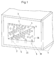
- Figure 1 shows a section of an incinerator 1.
- An insulation 3 is applied to the inner surfaces 2I of the incinerator 1. This is made of a 3V fiber composite. Part of this fiber composite material 3V are ceramic fibers, which are cast together with a binder to form the insulation 3.
- the insulation 3 shields a channel 4 in which a hot gas (not shown here) is directed in the direction of the arrow.
- a protection 5 is arranged on the surfaces 3S of the insulation 3. In the exemplary embodiment shown here, this protection 5 is formed by rod-shaped reinforcing elements 5.
- the rod-shaped reinforcing elements 5 are arranged such that their longitudinal axes run perpendicular to the surface 3S.
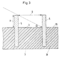
- the rod-shaped reinforcing elements 5 have a diameter of 2 to 5 mm. Their length is 10 to 25 mm. If the gas flows exclusively parallel to the surfaces 3S, the rod-shaped reinforcing elements 5 are arranged in the fiber composite material 3V in such a way that the ends of the rod-shaped reinforcing elements 5 facing the channel are flush with the surface 3S of the insulation 3 or a few mm in the surface 3S are sunk. As can be seen from FIG. 1, the rod-shaped reinforcing elements 5 are arranged irregularly when the gas flows parallel to the surfaces 3S of the insulation 3.
- the arrangement of the reinforcing elements 5 will result in an optimal surface structure after an initial heavy removal of the fiber composite material, since the destruction by the reinforcing elements 5 gradually emerging from the surface is completely prevented.
- a special arrangement of the rod-shaped reinforcing elements 5 is required.
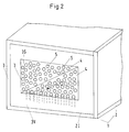
- the rod-shaped reinforcing elements are arranged in rows in the area of each surface 3S.
- the rod-shaped reinforcing elements 5 of two adjacent rows are additionally offset from one another, in such a way that, seen in the direction of flow of the hot gas, no free passages for the gas remain between the rod-shaped reinforcing elements 5.
- the distance between two reinforcing elements 5 of a row should at least correspond to the diameter of a reinforcing element 5. The same applies to the vertical distance between two adjacent rows of reinforcing elements 5.
- the reinforcing elements 5 shown in FIGS. 1 and 2 are already arranged in the area of the surfaces 3S when the fiber composite material 3V is being poured and directly through the binding phases that occur during the solidification of the fiber composite material 3V anchored. According to the invention, the reinforcing elements 5 can also be subsequently introduced into the insulation 3.
- the surfaces 3S of the insulation 3 must be provided with bores (not shown here) into which the rod-shaped reinforcing elements 5 can be lowered.
- the reinforcement elements 5 are then attached with the aid of a ceramic adhesive (not shown here).
- the length of the rod-shaped reinforcing elements 5 determines the service life and insulation effect of the fiber composite material 3V. Long rod-shaped reinforcing elements 5 reduce the insulation effect locally.
- An optimal insulating effect is achieved in that the rod-shaped reinforcing elements 5 are made of zirconium dioxide, since this material conducts heat only with 3 to 5.5 W ⁇ m ⁇ 1 ⁇ K ⁇ 1. However, they can also be made from Al2O3, mullite, magnesium oxide or a spinel.
- rod-shaped reinforcing elements 5 in this arrangement provide optimal protection.
- the hot gas has a flow angle ⁇ which is greater than 60 °, and if this hot gas is additionally loaded with particles, reinforcing elements 5, as shown in FIGS. 4 and 5, are preferably used. These are also rod-shaped reinforcing elements 5. However, at their end protruding from the surface 3S of the insulation, they are provided with a head 5K which is designed as a round or rectangular plate.
- the diameter of the head 5K corresponds approximately to ten times the rod-shaped part of the reinforcing element 5.
- Rod-shaped reinforcing elements 5 designed in this way can be used at any angle of incidence, without further measures having to be taken with regard to the arrangement of the reinforcing elements. However, these reinforcing elements 5 can break out of the fiber composite material 3V more easily than the reinforcing elements 5 without a head.
- additional anchoring elements (not shown here) are arranged at the first ends of these reinforcement elements, which are arranged far inside the insulation. Ceramic adhesives or organometallic precursors of the binder mixed with ceramic powders of the same type are suitable for this.
- Figure 6 shows a thermal insulation 3, the surface area 3S with plate-shaped reinforcing elements 5 is provided.
- These plate-shaped reinforcing elements 5 are also arranged in rows, in such a way that the planes of two adjacent reinforcing elements 5 run perpendicular to one another.
- the immediately adjacent rows of reinforcing elements 5 are arranged offset, so that the planes of two directly opposite reinforcing elements 5 are also arranged perpendicular to one another.
- FIG. 7 shows a top view of a further possibility of how plate-shaped reinforcing elements 5 can be arranged.
- the plate-shaped reinforcing elements 5 according to FIG. 8 are preferably arranged in the fiber composite material 3 such that their surfaces 5S form an angle between 10 ° and 70 °, preferably 45 ° and 60 °, with the surface 3S of the fiber composite material 3V.
Landscapes
- Engineering & Computer Science (AREA)
- Chemical & Material Sciences (AREA)
- Combustion & Propulsion (AREA)
- Mechanical Engineering (AREA)
- General Engineering & Computer Science (AREA)
- Thermal Insulation (AREA)
- Laminated Bodies (AREA)
- Furnace Housings, Linings, Walls, And Ceilings (AREA)
Applications Claiming Priority (2)
| Application Number | Priority Date | Filing Date | Title |
|---|---|---|---|
| DE4343120A DE4343120A1 (de) | 1993-12-17 | 1993-12-17 | Thermische Isolation |
| DE4343120 | 1993-12-17 |
Publications (3)
| Publication Number | Publication Date |
|---|---|
| EP0658723A2 true EP0658723A2 (fr) | 1995-06-21 |
| EP0658723A3 EP0658723A3 (fr) | 1996-04-10 |
| EP0658723B1 EP0658723B1 (fr) | 2000-05-31 |
Family
ID=6505306
Family Applications (1)
| Application Number | Title | Priority Date | Filing Date |
|---|---|---|---|
| EP94119579A Expired - Lifetime EP0658723B1 (fr) | 1993-12-17 | 1994-12-10 | Isolation thermique |
Country Status (4)
| Country | Link |
|---|---|
| US (1) | US5709919A (fr) |
| EP (1) | EP0658723B1 (fr) |
| JP (1) | JPH07253209A (fr) |
| DE (2) | DE4343120A1 (fr) |
Families Citing this family (8)
| Publication number | Priority date | Publication date | Assignee | Title |
|---|---|---|---|---|
| US6733907B2 (en) | 1998-03-27 | 2004-05-11 | Siemens Westinghouse Power Corporation | Hybrid ceramic material composed of insulating and structural ceramic layers |
| US6884384B2 (en) | 2001-09-27 | 2005-04-26 | Siemens Westinghouse Power Corporation | Method for making a high temperature erosion resistant material containing compacted hollow geometric shapes |
| US6610385B2 (en) * | 2001-12-20 | 2003-08-26 | General Electric Company | Integral surface features for CMC components and method therefor |
| GB2453946B (en) * | 2007-10-23 | 2010-07-14 | Rolls Royce Plc | A Wall Element for use in Combustion Apparatus |
| GB0800294D0 (en) * | 2008-01-09 | 2008-02-20 | Rolls Royce Plc | Gas heater |
| GB0801839D0 (en) * | 2008-02-01 | 2008-03-05 | Rolls Royce Plc | combustion apparatus |
| GB2457281B (en) * | 2008-02-11 | 2010-09-08 | Rolls Royce Plc | A Combustor Wall Arrangement with Parts Joined by Mechanical Fasteners |
| GB2460634B (en) * | 2008-06-02 | 2010-07-07 | Rolls Royce Plc | Combustion apparatus |
Family Cites Families (7)
| Publication number | Priority date | Publication date | Assignee | Title |
|---|---|---|---|---|
| US2564497A (en) * | 1947-11-26 | 1951-08-14 | Gen Electric | Combustion chamber liner |
| FR1215494A (fr) * | 1958-02-18 | 1960-04-19 | Plessey Co Ltd | Chambre de combustion pour réactions à haute température |
| DE3638658C1 (de) * | 1986-11-12 | 1988-04-21 | Daimler Benz Ag | Waermedaemmende Auskleidung fuer eine Gasturbine |
| US4709643A (en) * | 1987-02-24 | 1987-12-01 | Prutech Ii | Primary stage combustor lining |
| JPH076454B2 (ja) * | 1987-10-22 | 1995-01-30 | 航空宇宙技術研究所長 | 炭素複合材燃焼器 |
| WO1989012789A1 (fr) * | 1988-06-13 | 1989-12-28 | Siemens Aktiengesellschaft | Bouclier thermique n'exigeant que peu de fluide de refroidissement |
| US5331816A (en) * | 1992-10-13 | 1994-07-26 | United Technologies Corporation | Gas turbine engine combustor fiber reinforced glass ceramic matrix liner with embedded refractory ceramic tiles |
-
1993
- 1993-12-17 DE DE4343120A patent/DE4343120A1/de not_active Withdrawn
-
1994
- 1994-12-10 DE DE59409386T patent/DE59409386D1/de not_active Expired - Fee Related
- 1994-12-10 EP EP94119579A patent/EP0658723B1/fr not_active Expired - Lifetime
- 1994-12-16 JP JP6313820A patent/JPH07253209A/ja active Pending
- 1994-12-19 US US08/358,771 patent/US5709919A/en not_active Expired - Fee Related
Also Published As
| Publication number | Publication date |
|---|---|
| DE59409386D1 (de) | 2000-07-06 |
| DE4343120A1 (de) | 1995-06-22 |
| EP0658723B1 (fr) | 2000-05-31 |
| JPH07253209A (ja) | 1995-10-03 |
| US5709919A (en) | 1998-01-20 |
| EP0658723A3 (fr) | 1996-04-10 |
Similar Documents
| Publication | Publication Date | Title |
|---|---|---|
| EP0558540B1 (fr) | Ecran thermique en ceramique monte sur une structure portante | |
| EP2132393B1 (fr) | Verre de sécurité feuilleté anti-feu pour des éléments de construction comme des portes, murs ou fenêtres | |
| DE1957532A1 (de) | Ofenkonstruktion | |
| EP0658723B1 (fr) | Isolation thermique | |
| DE3307114C2 (de) | Zylinderkopf eines Kolbenmotors | |
| DE3116381C2 (de) | Druckelement in einem wärmedämmenden Fertigbauteil für vorkragende Gebäudeteile | |
| EP1390670A1 (fr) | Ensemble ecran thermique pour un composant conduisant un gaz chaud, et procede de fabrication dudit ensemble | |
| DE4025479A1 (de) | Keramikfasern verwendender industrieofen | |
| DE19523548C1 (de) | Kernreaktor mit einer Auffangkammer für Kernschmelze | |
| DE3614730A1 (de) | Feuerfester formkoerper, insbesondere platte fuer schieberverschluesse | |
| EP1288601A1 (fr) | Brique de protection thermique ainsi que son utilisation dans une chambre de combustion | |
| DE4324423C1 (de) | Feuerfeste Auskleidung von Wänden und Formstein hierfür | |
| EP1872075B1 (fr) | Element de bouclier thermique pour le revetement d'une paroi de chambre de combustion, chambre de combustion et turbine a gaz | |
| EP1359254B1 (fr) | Dispositif de recouvrement pour joints de dilatation dans des constructions | |
| DE2717209A1 (de) | Waermeisolierung | |
| EP1470367B1 (fr) | Plaque pour systeme de protection pour paroi de tube de chaudiere et systeme de protection pour paroi de tube de chaudiere | |
| DE2848114A1 (de) | Heissduese fuer raketentriebwerke | |
| WO2022253825A1 (fr) | Paroi pour four, brique réfractaire pour paroi d'un four, four, système de fixation, procédé de fixation d'une brique réfractaire dans une rainure et procédé de fabrication d'une paroi pour un four | |
| EP0340410A1 (fr) | Plaque de pierre naturelle avec des éléments de fixation sur sa partie non visible | |
| DE202008002982U1 (de) | Brenntisch für einen Ofen | |
| DE102004063813A1 (de) | Hitzeschutzkörper für ein Schutzsystem für eine Ofeninnenwand | |
| DE2818751C2 (fr) | ||
| DE4401008C2 (de) | Schieberplatte | |
| DE29619196U1 (de) | Vorrichtung zum Abdichten eines Ringraumes | |
| DE102023103668A1 (de) | Batteriegehäusedeckel mit einem Abschnitt umfassend einen Faserverbund mit oxidischer Matrix |
Legal Events
| Date | Code | Title | Description |
|---|---|---|---|
| PUAI | Public reference made under article 153(3) epc to a published international application that has entered the european phase |
Free format text: ORIGINAL CODE: 0009012 |
|
| AK | Designated contracting states |
Kind code of ref document: A2 Designated state(s): DE FR GB |
|
| PUAL | Search report despatched |
Free format text: ORIGINAL CODE: 0009013 |
|
| AK | Designated contracting states |
Kind code of ref document: A3 Designated state(s): DE FR GB |
|
| 17P | Request for examination filed |
Effective date: 19960917 |
|
| 17Q | First examination report despatched |
Effective date: 19980421 |
|
| GRAG | Despatch of communication of intention to grant |
Free format text: ORIGINAL CODE: EPIDOS AGRA |
|
| GRAG | Despatch of communication of intention to grant |
Free format text: ORIGINAL CODE: EPIDOS AGRA |
|
| GRAH | Despatch of communication of intention to grant a patent |
Free format text: ORIGINAL CODE: EPIDOS IGRA |
|
| GRAH | Despatch of communication of intention to grant a patent |
Free format text: ORIGINAL CODE: EPIDOS IGRA |
|
| GRAA | (expected) grant |
Free format text: ORIGINAL CODE: 0009210 |
|
| AK | Designated contracting states |
Kind code of ref document: B1 Designated state(s): DE FR GB |
|
| GBT | Gb: translation of ep patent filed (gb section 77(6)(a)/1977) |
Effective date: 20000612 |
|
| REF | Corresponds to: |
Ref document number: 59409386 Country of ref document: DE Date of ref document: 20000706 |
|
| ET | Fr: translation filed | ||
| PLBE | No opposition filed within time limit |
Free format text: ORIGINAL CODE: 0009261 |
|
| STAA | Information on the status of an ep patent application or granted ep patent |
Free format text: STATUS: NO OPPOSITION FILED WITHIN TIME LIMIT |
|
| 26N | No opposition filed | ||
| PGFP | Annual fee paid to national office [announced via postgrant information from national office to epo] |
Ref country code: FR Payment date: 20010927 Year of fee payment: 8 |
|
| PGFP | Annual fee paid to national office [announced via postgrant information from national office to epo] |
Ref country code: GB Payment date: 20011001 Year of fee payment: 8 |
|
| REG | Reference to a national code |
Ref country code: GB Ref legal event code: IF02 |
|
| PGFP | Annual fee paid to national office [announced via postgrant information from national office to epo] |
Ref country code: DE Payment date: 20020628 Year of fee payment: 8 |
|
| PG25 | Lapsed in a contracting state [announced via postgrant information from national office to epo] |
Ref country code: GB Free format text: LAPSE BECAUSE OF NON-PAYMENT OF DUE FEES Effective date: 20021210 |
|
| PG25 | Lapsed in a contracting state [announced via postgrant information from national office to epo] |
Ref country code: DE Free format text: LAPSE BECAUSE OF NON-PAYMENT OF DUE FEES Effective date: 20030701 |
|
| GBPC | Gb: european patent ceased through non-payment of renewal fee | ||
| PG25 | Lapsed in a contracting state [announced via postgrant information from national office to epo] |
Ref country code: FR Free format text: LAPSE BECAUSE OF NON-PAYMENT OF DUE FEES Effective date: 20030901 |
|
| REG | Reference to a national code |
Ref country code: FR Ref legal event code: ST |