EP0658725B1 - Verfahren und Vorrichtung zum Regeln des Durchflusses in einer Fernwärmeübergabestation - Google Patents
Verfahren und Vorrichtung zum Regeln des Durchflusses in einer Fernwärmeübergabestation Download PDFInfo
- Publication number
- EP0658725B1 EP0658725B1 EP94117391A EP94117391A EP0658725B1 EP 0658725 B1 EP0658725 B1 EP 0658725B1 EP 94117391 A EP94117391 A EP 94117391A EP 94117391 A EP94117391 A EP 94117391A EP 0658725 B1 EP0658725 B1 EP 0658725B1
- Authority
- EP
- European Patent Office
- Prior art keywords
- bypass line
- flow
- main
- cross
- valve
- Prior art date
- Legal status (The legal status is an assumption and is not a legal conclusion. Google has not performed a legal analysis and makes no representation as to the accuracy of the status listed.)
- Revoked
Links
- 238000010438 heat treatment Methods 0.000 title claims abstract description 13
- 238000000034 method Methods 0.000 title claims abstract description 11
- 230000001105 regulatory effect Effects 0.000 claims abstract description 23
- 239000003638 chemical reducing agent Substances 0.000 claims abstract description 21
- 230000009467 reduction Effects 0.000 claims description 3
- 238000011144 upstream manufacturing Methods 0.000 claims description 3
- 230000009471 action Effects 0.000 claims description 2
- 239000012528 membrane Substances 0.000 description 4
- 230000008901 benefit Effects 0.000 description 3
- XLYOFNOQVPJJNP-UHFFFAOYSA-N water Substances O XLYOFNOQVPJJNP-UHFFFAOYSA-N 0.000 description 3
- 238000013016 damping Methods 0.000 description 2
- 230000008569 process Effects 0.000 description 2
- 230000002411 adverse Effects 0.000 description 1
- 230000005540 biological transmission Effects 0.000 description 1
- 230000009172 bursting Effects 0.000 description 1
- 230000008878 coupling Effects 0.000 description 1
- 238000010168 coupling process Methods 0.000 description 1
- 238000005859 coupling reaction Methods 0.000 description 1
- 238000004519 manufacturing process Methods 0.000 description 1
Images


Classifications
-
- F—MECHANICAL ENGINEERING; LIGHTING; HEATING; WEAPONS; BLASTING
- F24—HEATING; RANGES; VENTILATING
- F24D—DOMESTIC- OR SPACE-HEATING SYSTEMS, e.g. CENTRAL HEATING SYSTEMS; DOMESTIC HOT-WATER SUPPLY SYSTEMS; ELEMENTS OR COMPONENTS THEREFOR
- F24D10/00—District heating systems
- F24D10/006—Direct domestic delivery stations
-
- Y—GENERAL TAGGING OF NEW TECHNOLOGICAL DEVELOPMENTS; GENERAL TAGGING OF CROSS-SECTIONAL TECHNOLOGIES SPANNING OVER SEVERAL SECTIONS OF THE IPC; TECHNICAL SUBJECTS COVERED BY FORMER USPC CROSS-REFERENCE ART COLLECTIONS [XRACs] AND DIGESTS
- Y02—TECHNOLOGIES OR APPLICATIONS FOR MITIGATION OR ADAPTATION AGAINST CLIMATE CHANGE
- Y02B—CLIMATE CHANGE MITIGATION TECHNOLOGIES RELATED TO BUILDINGS, e.g. HOUSING, HOUSE APPLIANCES OR RELATED END-USER APPLICATIONS
- Y02B30/00—Energy efficient heating, ventilation or air conditioning [HVAC]
- Y02B30/17—District heating
-
- Y—GENERAL TAGGING OF NEW TECHNOLOGICAL DEVELOPMENTS; GENERAL TAGGING OF CROSS-SECTIONAL TECHNOLOGIES SPANNING OVER SEVERAL SECTIONS OF THE IPC; TECHNICAL SUBJECTS COVERED BY FORMER USPC CROSS-REFERENCE ART COLLECTIONS [XRACs] AND DIGESTS
- Y02—TECHNOLOGIES OR APPLICATIONS FOR MITIGATION OR ADAPTATION AGAINST CLIMATE CHANGE
- Y02E—REDUCTION OF GREENHOUSE GAS [GHG] EMISSIONS, RELATED TO ENERGY GENERATION, TRANSMISSION OR DISTRIBUTION
- Y02E20/00—Combustion technologies with mitigation potential
- Y02E20/14—Combined heat and power generation [CHP]
-
- Y—GENERAL TAGGING OF NEW TECHNOLOGICAL DEVELOPMENTS; GENERAL TAGGING OF CROSS-SECTIONAL TECHNOLOGIES SPANNING OVER SEVERAL SECTIONS OF THE IPC; TECHNICAL SUBJECTS COVERED BY FORMER USPC CROSS-REFERENCE ART COLLECTIONS [XRACs] AND DIGESTS
- Y02—TECHNOLOGIES OR APPLICATIONS FOR MITIGATION OR ADAPTATION AGAINST CLIMATE CHANGE
- Y02P—CLIMATE CHANGE MITIGATION TECHNOLOGIES IN THE PRODUCTION OR PROCESSING OF GOODS
- Y02P80/00—Climate change mitigation technologies for sector-wide applications
- Y02P80/10—Efficient use of energy, e.g. using compressed air or pressurized fluid as energy carrier
- Y02P80/14—District level solutions, i.e. local energy networks
Definitions
- the invention relates to a method and a device for regulating the flow in a district heating transfer station.
- the high pressure of the District heating pipe to the district-heated building reduced be, at the same time in its piping system a certain pressure is to be maintained in a regulated manner. About that in addition to the flow through the district heating transfer station also a temperature control.
- the line diameter in larger district heating transfer stations are usually above a nominal diameter of DN 50.
- pressure regulators in auxiliary control circuit so-called pilot valves used.
- the adjustment paths that occur are the pressure regulators a heat transfer station due to high Load changes especially in low load mode in Summer when only domestic water is used and the heating is very difficult to correct.
- US-A-2,059,121 discloses a pressure control system for a gaseous medium with pressures above atmospheric pressure described in pipelines or the like, with which also relatively low gas pressures for a uniform pressure level at the outlet of the pressure regulator in the main line should be taken care of.
- a pressure reduction in Distribution lines at a distribution point starting from Transmission lines take place.
- the pressure control system points a flow controller at the distribution point of the main line and a control controller in a bypass Flow control through a Venturi tube.
- the regulation of the flow takes place via the pressure difference between the inflow side to the flow controller in the main line and the pressure in the area of the narrowing of the Venturi tube in the Bypass so that the main valve of the pressure regulator in the Main line is open at low flow rates and if the pressure on the outlet side of the pressure regulator is too high closed by means of a diaphragm actuator of the pressure regulator becomes.
- the stated object is achieved by a method with the features of claim 1 and by a Generic device with the features of the claim 5 solved.
- a bypass circuit is therefore provided, i.e. parallel to the main valve in the main line Bypass arranged in which, in addition to its own controller it a pressure reducer, a relief valve or one powered by a motor or by a thermal sensor Valve, in particular a cross-section reducer for production a pressure difference in the form of a Venturi nozzle, one Venturi tube, a Dall tube or the like is arranged.
- a pressure reducer a relief valve or one powered by a motor or by a thermal sensor Valve, in particular a cross-section reducer for production a pressure difference in the form of a Venturi nozzle, one Venturi tube, a Dall tube or the like is arranged.
- the flow in the Bypass line is regulated without auxiliary energy or the flow in the bypass is regulated by means of auxiliary energy becomes.
- the flow in the bypass line through a thermostat is regulated.
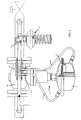
- FIGS Embodiments a main line 1 in a District heating transfer station for hot water transfer from the district heating network to the network of a building or the like.
- a District heating transfer station In the District heating transfer station is a regulated pressure reduction required.
- the main line 1 In the main line 1 is therefore an auxiliary controlled main valve 2a, which the Pressure reduced from a pressure P1 to a pressure P2.
- the main line has a nominal diameter of DN 50 to DN 250.
- a Bypass 3 above the main valve 2a has, for example Nominal size from DN 20 on.
- There is a bypass 3 Cross-section reducer 3a which locally reduces the Cross section up to, for example, a diameter of 12 mm.
- the cross section reducer 3a can Venturi nozzle, a Venturi tube or a Dall tube and is in particular a Venturi nozzle, as it is in concrete Training of Figure 5 can be seen.
- the auxiliary pressure regulator in the form of the main regulator 2 has a diaphragm drive 4.
- the membrane drive 4 has a closing spring acting on its membrane 5 6 on that in the sense of closing the main valve 2a acts.
- the two sub-chambers of the diaphragm drive 4 on both sides of the Membrane 5 are via control lines 7,8 with inlets 9,10 the nozzle 3a connected, namely the upstream of the narrowest Place the inlet 3a of the nozzle 3a via the line 7 with the main valve 2a of the control element 2 facing Side of the diaphragm actuator 4, the inlet 10 via the line 8 with the side of the valve facing away from the main valve 2a Membrane drive 4, ie the chamber part in which the Closing spring 6 is located.
- the reduced cross section of the Nozzle 3a becomes an adjustable when flowing through Practice about 0.5 to 0.8 bar negative pressure on the downstream side of the constriction with which the said chamber of the diaphragm drive facing away from the valve 2a is applied.
- the pressure in front of the reducer 3a i.e. the Venturi nozzle.
- the differential pressure depends on the volume flow through the Bypass line and controls the diaphragm drive. As long as the differential pressure a particularly through the closing spring 6 falls below the predetermined size, the main valve remains 2a closed and the regulation of the pressure P2 only takes place via the pressure reducer 11 larger flow through the bypass line opens that Valve 2a of the main control element 2 due to the larger Differential pressure against the action of the spring 6, so that Control element 2 is gently switched on. Through this gentle Switching on the main regulator becomes dangerous Vibrations in the control loop practically excluded. At Falling below a predetermined flow through the Bypass 3 becomes the main regulator gently in the same way closed.
- the diaphragm drive 4 assigned to the main valve 2a Main control element 2 is always simultaneously by one Pressure controlled, which is not the actual controlled variable, i.e. not from the differential pressure across the main valve 2a, but rather from the pressure drop at the cross-section reducer 3a.
- This has the advantage that the entire Device not influenced by the actual actual value pressure P1 and is therefore non-reactive.
- FIG. 2 shows an inventive one Device with a control element in the form of an auxiliary controlled Overflow valve.
- the auxiliary controller 11 in the form of an overflow regulator in the bypass line 3 upstream of the cross-section reducer 3a (again a Venturi tube) arranged.
- the way it works is basic the same as described with reference to FIG. 1 has been.
- the embodiment in FIG. 3 is a auxiliary controlled temperature controller, which is in the form of a Temperature sensor 12 instead of the control element 11 either mechanically steady on a valve 13 in the bypass line 3 works or by means of a motor drive for the Valve 13.
- a auxiliary controlled temperature controller which is in the form of a Temperature sensor 12 instead of the control element 11 either mechanically steady on a valve 13 in the bypass line 3 works or by means of a motor drive for the Valve 13.
- the advantage of the gentle closing and Switching off the main valve 2a of the main control element 2 in the main line 1 achieved in the same way as this the embodiments of Figures 1 and 2 is the case.
- FIG 4 now shows the combination of an auxiliary controller 11 in the form of a pressure reducer with an additional one Control device, such as an engine valve 14 or a mechanical Thermostat as explained in relation to Figure 3 has been.
- an auxiliary controller 11 in the form of a pressure reducer
- an additional one Control device such as an engine valve 14 or a mechanical Thermostat as explained in relation to Figure 3 has been.
- FIG. 5 shows a specific embodiment of the one in FIG 1 schematically illustrated device according to the invention. The parts described are clearly recognizable.
Landscapes
- Engineering & Computer Science (AREA)
- Physics & Mathematics (AREA)
- Thermal Sciences (AREA)
- Chemical & Material Sciences (AREA)
- Combustion & Propulsion (AREA)
- Mechanical Engineering (AREA)
- General Engineering & Computer Science (AREA)
- Control Of Fluid Pressure (AREA)
- Steam Or Hot-Water Central Heating Systems (AREA)
- Flow Control (AREA)
Applications Claiming Priority (2)
| Application Number | Priority Date | Filing Date | Title |
|---|---|---|---|
| DE4342531A DE4342531C2 (de) | 1993-12-14 | 1993-12-14 | Verfahren und Vorrichtung zum Regeln des Durchflusses in einer Fernwärmeübergabestation |
| DE4342531 | 1993-12-14 |
Publications (3)
| Publication Number | Publication Date |
|---|---|
| EP0658725A2 EP0658725A2 (de) | 1995-06-21 |
| EP0658725A3 EP0658725A3 (de) | 1995-12-27 |
| EP0658725B1 true EP0658725B1 (de) | 1999-01-27 |
Family
ID=6504924
Family Applications (1)
| Application Number | Title | Priority Date | Filing Date |
|---|---|---|---|
| EP94117391A Revoked EP0658725B1 (de) | 1993-12-14 | 1994-11-04 | Verfahren und Vorrichtung zum Regeln des Durchflusses in einer Fernwärmeübergabestation |
Country Status (4)
| Country | Link |
|---|---|
| EP (1) | EP0658725B1 (da) |
| AT (1) | ATE176310T1 (da) |
| DE (1) | DE4342531C2 (da) |
| DK (1) | DK0658725T3 (da) |
Families Citing this family (1)
| Publication number | Priority date | Publication date | Assignee | Title |
|---|---|---|---|---|
| DK178493B1 (en) * | 2014-09-29 | 2016-04-18 | Broen As | Valve unit |
Family Cites Families (3)
| Publication number | Priority date | Publication date | Assignee | Title |
|---|---|---|---|---|
| DE464893C (de) * | 1927-04-09 | 1928-08-30 | Julius Pintsch Akt Ges | Gasdruckregler |
| US2059121A (en) * | 1933-03-13 | 1936-10-27 | Milton E Lake | Pressure regulating system |
| DD269428A1 (de) * | 1988-02-02 | 1989-06-28 | Kwv Marzahn Veb | Druckminderer |
-
1993
- 1993-12-14 DE DE4342531A patent/DE4342531C2/de not_active Expired - Fee Related
-
1994
- 1994-11-04 EP EP94117391A patent/EP0658725B1/de not_active Revoked
- 1994-11-04 DK DK94117391T patent/DK0658725T3/da active
- 1994-11-04 AT AT94117391T patent/ATE176310T1/de not_active IP Right Cessation
Also Published As
| Publication number | Publication date |
|---|---|
| DE4342531C1 (de) | 1995-02-23 |
| EP0658725A2 (de) | 1995-06-21 |
| EP0658725A3 (de) | 1995-12-27 |
| DE4342531C2 (de) | 1997-10-09 |
| DK0658725T3 (da) | 1999-09-13 |
| ATE176310T1 (de) | 1999-02-15 |
Similar Documents
| Publication | Publication Date | Title |
|---|---|---|
| EP3105440A1 (de) | Druckregelvorrichtung für ein gasversorgungssystem einer gasturbinenanlage | |
| EP0907052A2 (de) | Pneumatischer Verhältnisregler | |
| CH621855A5 (en) | Method for regulating turbo-compressors | |
| EP0658725B1 (de) | Verfahren und Vorrichtung zum Regeln des Durchflusses in einer Fernwärmeübergabestation | |
| DE60004823T2 (de) | Steuerventil | |
| DE2637256C2 (de) | Regeleinrichtung für eine Extraktionsdampfturbine | |
| EP0771950B1 (de) | Verfahren zum Schutz eines Turbokompressors vor Betrieb im instabilen Arbeitsbereich mittels Armaturen mit zwei Stellgeschwindigkeiten | |
| DE19824630B4 (de) | Ventilkombination aus einem Membranregler, einer Drossel und einem Regelventil | |
| WO2003023288A1 (de) | Zentralheizungsanlage | |
| DE19618093C2 (de) | Vorrichtung zur Regelung der Temperatur von Brauchwasser | |
| DE2558509A1 (de) | Regeleinrichtung fuer einen durchlauferhitzer | |
| EP0065033A2 (de) | Heizanlage zu einem Fernheizsystem | |
| CH365094A (de) | Wärmeaustauscher | |
| DE69400929T2 (de) | Flüssigkeits-Verteilnetz mit Regler | |
| DE2722890C2 (de) | Kaskadenregelung für eine Warmwasserheizungs- oder -bereitungsanlage | |
| DD201041A1 (de) | Verfahren und einrichtung zur druckstossbegrenzung in rohrleitungen | |
| DE19907509A1 (de) | Verfahren zur Regelung einer Fernwärmtherme und Regelsystem zur Durchführung dieses Verfahrens | |
| DE851705C (de) | Verfahren zur Regelung von Gaserhitzern und Gaserhitzer zur Ausfuehrung des Verfahrens | |
| EP3472514A1 (de) | Verfahren zum betreiben eines abhitzedampferzeugers | |
| DE623285C (de) | Einrichtung zur Regelung einer auf Leistung geregelten Gegendruckmaschine | |
| DE719189C (de) | Druckregelvorrichtung, insbesondere des Druckes eines von Anzapfdampfturbinen gespeisten Netzes | |
| DE267933C (da) | ||
| DE232821C (da) | ||
| EP0494330A1 (de) | Brennschneidmaschine mit massenstromgesteuerter Versorgung des Schneidbrenners | |
| DE1426850C (de) | Hydraulische Regeleinrichtung fur Dampfturbinenanlagerf mit Zwischenuber hitzer |
Legal Events
| Date | Code | Title | Description |
|---|---|---|---|
| PUAI | Public reference made under article 153(3) epc to a published international application that has entered the european phase |
Free format text: ORIGINAL CODE: 0009012 |
|
| AK | Designated contracting states |
Kind code of ref document: A2 Designated state(s): AT CH DK FR LI NL |
|
| PUAL | Search report despatched |
Free format text: ORIGINAL CODE: 0009013 |
|
| AK | Designated contracting states |
Kind code of ref document: A3 Designated state(s): AT CH DK FR LI NL |
|
| 17P | Request for examination filed |
Effective date: 19951223 |
|
| 17Q | First examination report despatched |
Effective date: 19970403 |
|
| GRAG | Despatch of communication of intention to grant |
Free format text: ORIGINAL CODE: EPIDOS AGRA |
|
| GRAG | Despatch of communication of intention to grant |
Free format text: ORIGINAL CODE: EPIDOS AGRA |
|
| GRAH | Despatch of communication of intention to grant a patent |
Free format text: ORIGINAL CODE: EPIDOS IGRA |
|
| GRAH | Despatch of communication of intention to grant a patent |
Free format text: ORIGINAL CODE: EPIDOS IGRA |
|
| GRAA | (expected) grant |
Free format text: ORIGINAL CODE: 0009210 |
|
| AK | Designated contracting states |
Kind code of ref document: B1 Designated state(s): AT CH DK FR LI NL |
|
| REF | Corresponds to: |
Ref document number: 176310 Country of ref document: AT Date of ref document: 19990215 Kind code of ref document: T |
|
| REG | Reference to a national code |
Ref country code: CH Ref legal event code: EP |
|
| REG | Reference to a national code |
Ref country code: CH Ref legal event code: NV Representative=s name: TROESCH SCHEIDEGGER WERNER AG |
|
| ET | Fr: translation filed | ||
| REG | Reference to a national code |
Ref country code: DK Ref legal event code: T3 |
|
| PLBQ | Unpublished change to opponent data |
Free format text: ORIGINAL CODE: EPIDOS OPPO |
|
| PLBI | Opposition filed |
Free format text: ORIGINAL CODE: 0009260 |
|
| PLBF | Reply of patent proprietor to notice(s) of opposition |
Free format text: ORIGINAL CODE: EPIDOS OBSO |
|
| 26 | Opposition filed |
Opponent name: HELMUT BAELZ GMBH Effective date: 19991027 |
|
| NLR1 | Nl: opposition has been filed with the epo |
Opponent name: HELMUT BAELZ GMBH |
|
| PLBF | Reply of patent proprietor to notice(s) of opposition |
Free format text: ORIGINAL CODE: EPIDOS OBSO |
|
| PGFP | Annual fee paid to national office [announced via postgrant information from national office to epo] |
Ref country code: AT Payment date: 20001114 Year of fee payment: 7 |
|
| PGFP | Annual fee paid to national office [announced via postgrant information from national office to epo] |
Ref country code: DK Payment date: 20001122 Year of fee payment: 7 |
|
| PGFP | Annual fee paid to national office [announced via postgrant information from national office to epo] |
Ref country code: NL Payment date: 20001123 Year of fee payment: 7 |
|
| PGFP | Annual fee paid to national office [announced via postgrant information from national office to epo] |
Ref country code: FR Payment date: 20001129 Year of fee payment: 7 |
|
| RAP2 | Party data changed (patent owner data changed or rights of a patent transferred) |
Owner name: DANFOSS IWK REGLER GMBH |
|
| PGFP | Annual fee paid to national office [announced via postgrant information from national office to epo] |
Ref country code: CH Payment date: 20010208 Year of fee payment: 7 |
|
| REG | Reference to a national code |
Ref country code: CH Ref legal event code: PUE Owner name: IWK REGLER UND KOMPENSATOREN GMBH TRANSFER- IWK RE |
|
| NLT2 | Nl: modifications (of names), taken from the european patent patent bulletin |
Owner name: DANFOSS IWK REGLER GMBH |
|
| RDAH | Patent revoked |
Free format text: ORIGINAL CODE: EPIDOS REVO |
|
| NLS | Nl: assignments of ep-patents |
Owner name: DANFOSS IWK REGLER GMBH |
|
| REG | Reference to a national code |
Ref country code: FR Ref legal event code: TP |
|
| RDAG | Patent revoked |
Free format text: ORIGINAL CODE: 0009271 |
|
| STAA | Information on the status of an ep patent application or granted ep patent |
Free format text: STATUS: PATENT REVOKED |
|
| 27W | Patent revoked |
Effective date: 20010216 |
|
| REG | Reference to a national code |
Ref country code: CH Ref legal event code: PL |
|
| NLR2 | Nl: decision of opposition |