EP0658727A2 - Sortie d'air empêchant la condensation - Google Patents
Sortie d'air empêchant la condensation Download PDFInfo
- Publication number
- EP0658727A2 EP0658727A2 EP94308867A EP94308867A EP0658727A2 EP 0658727 A2 EP0658727 A2 EP 0658727A2 EP 94308867 A EP94308867 A EP 94308867A EP 94308867 A EP94308867 A EP 94308867A EP 0658727 A2 EP0658727 A2 EP 0658727A2
- Authority
- EP
- European Patent Office
- Prior art keywords
- air flow
- damper
- vent structure
- condensation preventing
- innermost
- Prior art date
- Legal status (The legal status is an assumption and is not a legal conclusion. Google has not performed a legal analysis and makes no representation as to the accuracy of the status listed.)
- Withdrawn
Links
Images


Classifications
-
- F—MECHANICAL ENGINEERING; LIGHTING; HEATING; WEAPONS; BLASTING
- F24—HEATING; RANGES; VENTILATING
- F24F—AIR-CONDITIONING; AIR-HUMIDIFICATION; VENTILATION; USE OF AIR CURRENTS FOR SCREENING
- F24F13/00—Details common to, or for air-conditioning, air-humidification, ventilation or use of air currents for screening
- F24F13/02—Ducting arrangements
- F24F13/06—Outlets for directing or distributing air into rooms or spaces, e.g. ceiling air diffuser
- F24F13/068—Outlets for directing or distributing air into rooms or spaces, e.g. ceiling air diffuser formed as perforated walls, ceilings or floors
-
- F—MECHANICAL ENGINEERING; LIGHTING; HEATING; WEAPONS; BLASTING
- F24—HEATING; RANGES; VENTILATING
- F24F—AIR-CONDITIONING; AIR-HUMIDIFICATION; VENTILATION; USE OF AIR CURRENTS FOR SCREENING
- F24F13/00—Details common to, or for air-conditioning, air-humidification, ventilation or use of air currents for screening
- F24F13/02—Ducting arrangements
- F24F13/06—Outlets for directing or distributing air into rooms or spaces, e.g. ceiling air diffuser
-
- F—MECHANICAL ENGINEERING; LIGHTING; HEATING; WEAPONS; BLASTING
- F24—HEATING; RANGES; VENTILATING
- F24F—AIR-CONDITIONING; AIR-HUMIDIFICATION; VENTILATION; USE OF AIR CURRENTS FOR SCREENING
- F24F13/00—Details common to, or for air-conditioning, air-humidification, ventilation or use of air currents for screening
- F24F13/22—Means for preventing condensation or evacuating condensate
Definitions
- the present invention relates to a vent structure for an air conditioner, and more precisely, relates to a vent structure able to prevent condensation.
- an air blowing outlet is provided in a wall or a ceiling of a room in a building, or other structure, to discharge air to thereby to carry out air-conditioning.
- the multiple-flow type vent in which air is radially discharged from the entire periphery thereof, have been widely used as vents attached to the ceiling of a room, etc.
- the multiple-flow type vent is in the form of a hollow and substantially frusto-conical vent frame which is provided therein with a plurality of fins arranged concentrically with the vent frame.
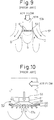
- Figure 10 shows an example of a known vent 50 which is attached to an opening 100 formed in the ceiling 101 and, through a neck 51, to a duct connecting port 53, so that the vent faces downward.
- the vent 50 is provided with a hollow and substantially truncated-cone-shaped vent frame (casing) 55 in which a plurality of concentric conical fins 57 are supported, so that air can be discharged in the radial direction from the outlet.
- the innermost (or central) conical fin 57a is provided with a closed top end. Consequently, there is no air flow within the innermost fin. Therefore, when the air-conditioning air is radially discharged from the air passages defined between the adjacent conical fins 57, the hot air in the room, drawn into the vicinity of the innermost fin 57a by the flow of cold air discharged from the vent 50 comes into contact with the cold air, resulting in the formation of condensation on the inner surface of the innermost fin 57a, due to the difference between the temperatures of the hot air and of the cold air. The condensation not only causes the vent to rust, but also deteriorates the appearance of the vent.
- an innermost fin 57A having an open upper end 57B as shown in Fig. 9 and as disclosed, for example, in Japanese Utility Model Unexamined Publication (Kokai) No. 5-52647.
- a plate 59 having a number of through holes 61 is provided in the innermost fin 57A.
- an air flow is caused within the innermost fin 57A to prevent the occurrence of condensation.
- a condensation-preventing vent structure having therein at least one fin, including an innermost fin, to define a flow passage of air, said innermost fin being provided with open upper and lower ends to define therein a flow passage, and provision being made of an air flow damper, provided on the upstream side of the innermost fin, to reduce the air flow at the central portion of the flow passage.
- the air flow damper can be comprised of a perforated damper and the perforated damper can be made of a mesh or perforated plate with a number of holes.
- the damper is in the form of a paraboloid of revolution whose diameter gradually decreases toward the downstream side of the air flow, or in the form of a cone whose diameter gradually decreases toward the downstream side of the air flow.
- the damper can be provided, on the central portion thereof, with a high impedance smooth flow restricting portion and, on the surrounding portion, with a low impedance smooth flow permitting portion connected to the high impedance portion.
- the perforated damper has a perforation density distribution in which the perforation density gradually increases from the center portion toward the peripheral portion thereof to gradually reduce the degree of obstruction to the air flow.
- a condensation preventing vent structure comprises a plurality of concentric fins including an innermost fin which is provided with open upper and lower ends, air flow passages defined by the adjacent fins, an inner air flow passage defined within the innermost fin, and an air flow damper provided in, or upstream of, the inner air flow passage defined within the innermost fin to locally restrict the air flow at the central portion of the inner flow passage.
- the innermost fin is provided with open upper and lower ends to define therein the inner air passage and an air flow damper to restrict the air flow at the central portion of the inner air passage, the velocity of the air flow in the central area of the inner flow passage is lower than the velocity of the air flow in the surrounding area and along the inner surface (guide surface) of the innermost fin. Consequently, no separation of the air flow in the vicinity of the inner surface of the innermost fin occurs. Namely, there is sufficient air flow in the vicinity of, or along the inner surface of, the innermost fin. Furthermore, there is also a slight or weak air flow in the central area of the inner air passage. Consequently, no hot air from the room is drawn into the central area due to the absence of an air flow in the central area, and thus, no condensation is formed on the inner surface of the innermost fin.
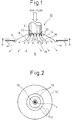
- Fig. 1 shows an embodiment of a condensation-preventing-vent structure (referred to as a vent) 10 according to the present invention.
- the vent 10 is attached to an opening K formed in a ceiling C within a room R with the air discharging end facing the inside of the room R, so that the vent 10 is located behind the ceiling C as viewed from the inside of the room R.
- the vent 10 is in the form of truncated cone and is made of metal, a light alloy or a synthetic resin.
- the vent 10 is comprised of an upper hollow neck 12 and a hollow conical vent frame 14 connected thereto.
- the vent 10 is circular, and accordingly, the fins 16 constitute a multilayered cone structure.
- the fins 16 are spaced from one another to define therebetween annular air passages 17, so that air can be radially discharged from the air passages 17 into the room R.
- the fins 16 including the innermost fin 18 are connected and secured to the inner surface of the neck 12 through respective mounting members 20 in the form of annular discs of different diameters.
- Figures 3 and 4 show the innermost blade 18 in the first embodiment of the present invention shown in Figs. 1 and 2.
- the innermost fin 18 has open upper and lower ends which permit air to flow therethrough.
- the innermost fin 18 is provided therein with a perforated damper 22, located at the upstream side thereof, i.e., mounted at the upper end thereof in the illustrated embodiment.
- the perforated damper 22 constitutes an air flow damping means for damping or decelerating the air flow.
- the damper 22 is very simple in structure and can be extremely easily mounted onto the innermost fin 18.
- the air flow damping means damps or decelerates the air flow particularly at the central portion of the flow passage within the innermost fin 18, that is, it resists or bars the flow at the central portion of the flow passage. Consequently, the flow at the central portion of the flow passage is less rapid than the flow along or in the vicinity of the inner conical surface 18a of the innermost fin 18.
- the damper 22 is made of a generally inexpensive mesh in the form of a bowl or paraboloid of revolution, having a diameter gradually decreasing toward the lower end thereof, i.e. toward the downstream side of the air flow.
- the damper 22 has a flat bottom 24 at the lower end (i.e., downstream side end) thereof and is secured at the upper end 27 (i.e., upstream side end) thereof, to the inner wall surface (guide surface) 18a of the innermost fin 18.
- a paraboloid surface 26 extends between the flat bottom 24 and the upper end 27.
- the flat bottom 24 has a lower perforation density than that of the side peripheral surface (i.e., the paraboloid surface) 26. Namely, the mesh of the flat bottom 24 is more dense than the mesh of the paraboloid surface 26, as can be seen in Fig. 4. Consequently, the flat bottom portion (high impedance portion) 24 restricts the air flow more than the side peripheral portion (low impedance portion) 26 does.
- the damper 22 is in the form of a paraboloid of revolution in the first embodiment mentioned above, it can be made of, for example a planar mesh 22' as shown in Fig. 6.
- the planar mesh has a non-uniform perforation density distribution (mesh density). That is, the center portion (corresponding to the high impedance portion) of the planar mesh 22' is more dense than the circumferential portion (corresponding to the low impedance portion) thereof.
- the embodiment shown in Figs. 3 and 4 is more preferable than the embodiment shown in Fig. 6 because, in the paraboloid-shaped mesh, a velocity component in a direction normal to the direction of the major flow is generated when the air passes through the mesh of the paraboloid surface 26 (Figs.
- This velocity component of the air flow causes an air flow along the inner surface 18a of the innermost fin 18. Consequently, it is ensured that there is a sufficient amount of air flow in the vicinity of, or along the inner surface 18a of, the innermost fin 18, unlike the prior art in which a separation of the air flow from the inner surface tends to occur, thus resulting in little or no air flow along, or in the vicinity of, the inner surface of the innermost fin, leading to the formation of the condensation, as mentioned above.
- planar mesh 22' includes the high impedance portion 24 at the center thereof and the low impedance portion 26 surrounding the same in Fig. 5, it is possible to provide a planar mesh having a perforation density distribution which gradually and continuously increases from the center to the periphery thereof, to thereby gradually reduce the degree of obstruction to the air flow toward the peripheral portion of the planar mesh 22'.
- the planar mesh 22' can be replaced with a metal or plastic plate 22'' which is provided with a large number of perforations punched therein.
- the perforations can be integrally formed during molding.
- Figure 5 shows another embodiment of a perforated damper 22A which is made of a mesh in the form of a perfect paraboloid of revolution.
- the same technical effects as those of the previous embodiments can be expected from the arrangement shown in Fig. 5.
- the mesh 22A can be also replaced with a plate 22A' having a large number of punched perforations.
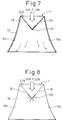
- Figure 7 shows another embodiment of an air flow damping means provided on the innermost fin 18 of the vent 10 according to the present invention.
- the perforated damper 22B is made of a mesh or a perforated plate with punched perforations in the form of a cone whose apex faces downward. Namely, the base portion of the cone having the largest diameter is secured to the inner surface 18a of the innermost fin 18 at the top end thereof.
- a velocity component of the air flow in the direction toward the inner surface 18a of the innermost fin 18 is generated when the air is discharged from the mesh or perforations of the cone in the downstream direction, similar to the above-mentioned embodiment.
- This velocity component of the air flow causes an air flow along the inner surface 18a of the innermost fin 18. Consequently, there is sufficient air flow in the vicinity of or along the inner surface 18a of, the innermost fin 18.
- the perforated damper 22B includes the high impedance portion 24 in the vicinity of the apex of the cone and the low impedance portion 26 on the conical surface other than the high impedance portion 24, similar to the above-mentioned embodiments. Consequently, the air flow at the central portion of the flow passage within the perforated damper 22B is obstructed or decelerated, and the air flow in the vicinity of, or along the inner surface 18a of, the innermost fin 18 is faster than the obstructed air flow at the central portion of the flow passage.
- Figure 8 shows a modification of the arrangement shown in Fig. 7.
- a restricting plate 28 in the form of a small hollow cone is provided at the center portion, i.e., the apex of the cone 22B shown in Fig. 7.
- the restricting plate 28 closes or interrupts the flow passage only in the vicinity of the apex of the cone, i.e., only a limited area of the flow passage at the center portion thereof.
- an air flow component along the restricting plate 28 is produced on the downstream side thereof by the air stream deflected by the restricting plate 28 and flowing toward the downstream side, as indicated by arrows in Fig. 8. Consequently, the hot air in the room R is not attracted into the center portion of the flow passage within the innermost fin 18, thus no condensation occurs on the inner wall surface of the innermost fin.
- the restricting plate 28 can be equally applied to any type or shape or material of the perforated damper (22, 22', 22'', 22A, 22A', 22B).
- the restricting plate 28 can be supported at the center portion of the flow passage within the innermost fin by a mounting arm or rod (not shown), etc.
- the absence of the perforated damper simplifies the vent structure, reduces the manufacturing cost and the number of manufacturing processes thereof. Moreover, the vents can be cheaply mass-produced.
- the present invention is not limited thereto.
- the condensation preventing vent structure of the present invention can be applied to a vent having therein a single fin which can be considered to be equivalent to the innermost fin discussed above.
- the shape of the vent is not limited to a circle as in the illustrated embodiments, and can be any shape including an angular shape.
- the air flow damping means which is provided at the upper end of the innermost fin in the illustrated embodiments can be provided above the upper end of the innermost fin or even at a position further downstream than the arrangement shown in the drawings, as long as the air flow separation preventing effect can be retained.
- the innermost fin is provided with open upper and lower ends to define therein an inner air flow passage, and the air flow damper is provided on the upstream side of the innermost fin to damp the air flow at the central portion of the inner air flow passage, the velocity of the air flow in the central area of the inner flow passage is relatively less than that of the air flow in the vicinity of, or along the inner surface of, the innermost fin. Therefore, no separation of the air flow in the vicinity of the inner surface of the innermost fin occurs, that is, there is a sufficient amount of air flow in the vicinity of, or along the inner surface of, the innermost fin.
- the air flow damper can be easily realized by a perforated damper which can be easily and inexpensively made of a mesh or a perforated plate with a number or holes.
- the perforated damper is in the form of a paraboloid of revolution whose diameter gradually decreases toward the downstream side of the air flow, or in the form of a cone whose diameter gradually decreases toward the downstream side of the air flow, an air flow component toward the inner wall surface of the innermost fin can be easily and certainly produced.
- the perforated damper is provided, on the central portion thereof, with a high impedance flow obstructing portion and, on the surrounding portion of the high impedance portion, with a low impedance smooth flow permitting portion connected to the high impedance portion, the flow restriction effect, particularly at the central portion of the inner flow passage, can be enhanced.
- the perforated damper has a perforation density distribution in which the perforation density gradually increases from the center portion toward the peripheral portion thereof to gradually reduce the degree of obstruction to the air flow.
- the air flow damper is comprised of a restricting plate provided at the center portion of the flow passage defined within the innermost fin the air flow damper can be simplified and easily and inexpensively produced.
Landscapes
- Engineering & Computer Science (AREA)
- Chemical & Material Sciences (AREA)
- Combustion & Propulsion (AREA)
- Mechanical Engineering (AREA)
- General Engineering & Computer Science (AREA)
- Air-Flow Control Members (AREA)
- Duct Arrangements (AREA)
- Turbine Rotor Nozzle Sealing (AREA)
Applications Claiming Priority (2)
| Application Number | Priority Date | Filing Date | Title |
|---|---|---|---|
| JP343418/93 | 1993-12-15 | ||
| JP34341893A JP3458244B2 (ja) | 1993-12-15 | 1993-12-15 | 結露防止型吹出口 |
Publications (2)
| Publication Number | Publication Date |
|---|---|
| EP0658727A2 true EP0658727A2 (fr) | 1995-06-21 |
| EP0658727A3 EP0658727A3 (fr) | 1996-08-14 |
Family
ID=18361367
Family Applications (1)
| Application Number | Title | Priority Date | Filing Date |
|---|---|---|---|
| EP94308867A Withdrawn EP0658727A3 (fr) | 1993-12-15 | 1994-11-30 | Sortie d'air empêchant la condensation. |
Country Status (8)
| Country | Link |
|---|---|
| US (1) | US5735738A (fr) |
| EP (1) | EP0658727A3 (fr) |
| JP (1) | JP3458244B2 (fr) |
| KR (1) | KR0163363B1 (fr) |
| CN (1) | CN1108378A (fr) |
| AU (1) | AU7902094A (fr) |
| MY (1) | MY131772A (fr) |
| SG (1) | SG50435A1 (fr) |
Cited By (2)
| Publication number | Priority date | Publication date | Assignee | Title |
|---|---|---|---|---|
| SG101968A1 (en) * | 1999-11-01 | 2004-02-27 | Kuken Kogyo Co Ltd | Blown gas outlet apparatus |
| US9709193B2 (en) | 2013-01-24 | 2017-07-18 | Rite-Hite Holding Corporation | Pliable air ducts with anti-condensation nozzles |
Families Citing this family (15)
| Publication number | Priority date | Publication date | Assignee | Title |
|---|---|---|---|---|
| JP2007269114A (ja) * | 2006-03-30 | 2007-10-18 | Toyoda Gosei Co Ltd | 空調用レジスタ |
| FI20065625A7 (fi) * | 2006-10-03 | 2008-04-04 | Halton Oy | Ilmanvaihdon päätelaite |
| US20080176506A1 (en) * | 2007-01-22 | 2008-07-24 | Rite-Hite Holding Corporation | Fabric diffuser with programmed airflow |
| US9039503B2 (en) | 2008-02-29 | 2015-05-26 | Rite-Hite Holding Corporation | Longitudinally split fabric air duct |
| US9482439B2 (en) * | 2011-10-10 | 2016-11-01 | Salman Akhtar | Air handling device |
| CN103355182A (zh) * | 2012-03-26 | 2013-10-23 | 凌云博际(北京)科技有限公司 | 用于通气笼的气嘴及独立通气笼 |
| US20140242901A1 (en) * | 2013-02-22 | 2014-08-28 | Treasure Unicorn Limited | Airflow outlet of air-conditioning device |
| CN103925634A (zh) * | 2014-04-25 | 2014-07-16 | 东南大学 | 基于太阳能集热水箱的室内供暖装置 |
| CN106196394B (zh) * | 2016-08-29 | 2022-03-25 | 珠海格力电器股份有限公司 | 送风设备及其多孔板 |
| US11293663B2 (en) * | 2017-01-26 | 2022-04-05 | Rite-Hite Holding Corporation | Fabric drop-down diffusers |
| US11231202B2 (en) | 2017-01-26 | 2022-01-25 | Rite-Hite Holding Corporation | Fabric drop-down diffusers |
| CN110017594B (zh) * | 2019-05-16 | 2023-06-23 | 安徽扬子空调股份有限公司 | 一种可避免凝露的空调导风板出风结构以及空调导风板 |
| RU2716291C1 (ru) * | 2019-08-07 | 2020-03-11 | Владимир Викторович Коваленко | Устройство для раздачи приточного воздуха (варианты) |
| CN112503674B (zh) * | 2020-11-03 | 2022-07-22 | 深圳供电局有限公司 | 通风结构及电缆防护装置 |
| CN116658974B (zh) * | 2022-02-18 | 2025-09-16 | 青岛海尔空调器有限总公司 | 用于空调器的出风装置及空调器 |
Family Cites Families (12)
| Publication number | Priority date | Publication date | Assignee | Title |
|---|---|---|---|---|
| US2407284A (en) * | 1942-06-20 | 1946-09-10 | Barber Colman Co | Air distribution outlet |
| US2403291A (en) * | 1942-12-08 | 1946-07-02 | Anemostat Corp | Damper |
| US2618215A (en) * | 1943-07-01 | 1952-11-18 | Fitt Thomas Charles | Ventilating device and like air supply and distributing device |
| DE1222224B (de) * | 1964-05-22 | 1966-08-04 | Anemostat Raumlufttechnik G M | Verstellbarer Luftverteiler |
| DE7820323U1 (de) * | 1978-07-06 | 1978-10-19 | Gebrueder Trox Gmbh, 4133 Neukirchen- Vluyn | Deckenluftauslass fuer klimaanlagen |
| DE2833822C2 (de) * | 1978-08-02 | 1982-01-21 | Werner Ing.(Grad.) 8781 Eussenheim Reith | Decken-Luftauslaßvorrichtung für variablen Volumenstrom zur Raumbelüftung |
| JPS6484013A (en) * | 1987-09-22 | 1989-03-29 | Matsushita Electric Industrial Co Ltd | Burner device |
| DE3741839A1 (de) * | 1987-12-10 | 1989-06-22 | Schako Metallwarenfabrik | Auslass fuer warm- und/oder kaltluft in raeumlichkeiten |
| JPH04198655A (ja) * | 1990-11-28 | 1992-07-20 | Sanbetsuku Kk | 空調装置における結露防止用吹出し口 |
| JPH0552647A (ja) * | 1991-08-27 | 1993-03-02 | Fujitsu Ltd | 赤外線撮像装置の試験装置 |
| AU650486B2 (en) * | 1991-10-29 | 1994-06-23 | University Of Bath | Localised clean air system |
| NZ247231A (en) * | 1993-03-23 | 1994-10-26 | Holyoake Ind Ltd | Diffuser for air conditioning system; outlet air direction thermostatically controlled |
-
1993
- 1993-12-15 JP JP34341893A patent/JP3458244B2/ja not_active Expired - Fee Related
-
1994
- 1994-11-24 AU AU79020/94A patent/AU7902094A/en not_active Abandoned
- 1994-11-28 MY MYPI94003164A patent/MY131772A/en unknown
- 1994-11-30 EP EP94308867A patent/EP0658727A3/fr not_active Withdrawn
- 1994-11-30 SG SG1996001386A patent/SG50435A1/en unknown
- 1994-12-14 CN CN94119085A patent/CN1108378A/zh active Pending
- 1994-12-15 KR KR1019940034433A patent/KR0163363B1/ko not_active Expired - Fee Related
-
1996
- 1996-08-13 US US08/694,464 patent/US5735738A/en not_active Expired - Fee Related
Cited By (2)
| Publication number | Priority date | Publication date | Assignee | Title |
|---|---|---|---|---|
| SG101968A1 (en) * | 1999-11-01 | 2004-02-27 | Kuken Kogyo Co Ltd | Blown gas outlet apparatus |
| US9709193B2 (en) | 2013-01-24 | 2017-07-18 | Rite-Hite Holding Corporation | Pliable air ducts with anti-condensation nozzles |
Also Published As
| Publication number | Publication date |
|---|---|
| JP3458244B2 (ja) | 2003-10-20 |
| KR0163363B1 (ko) | 1999-01-15 |
| JPH07167486A (ja) | 1995-07-04 |
| EP0658727A3 (fr) | 1996-08-14 |
| CN1108378A (zh) | 1995-09-13 |
| SG50435A1 (en) | 1998-07-20 |
| AU7902094A (en) | 1995-07-13 |
| US5735738A (en) | 1998-04-07 |
| MY131772A (en) | 2007-08-30 |
| KR950019527A (ko) | 1995-07-24 |
Similar Documents
| Publication | Publication Date | Title |
|---|---|---|
| US5735738A (en) | Condensation preventing vent structure | |
| EP1357337B1 (fr) | Grille de protection d'unite de ventilation | |
| US2644389A (en) | Diffuser for air conditioning systems | |
| US5460485A (en) | Blower with an improved shroud assembly | |
| JP6588091B2 (ja) | 空気清浄機及びその空気流路構成 | |
| US6139426A (en) | Molded polymer air diffusing screen | |
| US11904660B2 (en) | Air vent including mesh panel with improved directivity | |
| US4100938A (en) | Flow control unit for air distribution system | |
| US3554112A (en) | Ceiling air terminal | |
| JP4185820B2 (ja) | 吹出口およびそれを使用した空調方法 | |
| JPH05195995A (ja) | 遠心式送風機 | |
| JP3933280B2 (ja) | 吹出口装置 | |
| JPH07260241A (ja) | 床通気口 | |
| JP2020159637A (ja) | 天井埋め込み形空気調和機 | |
| JPH07248149A (ja) | 吹出口の内部構造 | |
| JPS61195235A (ja) | 流れ方向制御装置 | |
| JP4726404B2 (ja) | 低温空調用吹出口 | |
| JPH06505943A (ja) | 乗物用換気設備の分配ユニット | |
| JP4286944B2 (ja) | フィルタユニット用の気流制御板 | |
| EP4124807B1 (fr) | Diffuseur amélioré pour systèmes de ventilation | |
| CA2369490C (fr) | Reservoir de terminaison d'event avec registre | |
| JP3325796B2 (ja) | 換気口 | |
| JPH05106871A (ja) | セパレート型空気調和機の室外機 | |
| WO2009005447A1 (fr) | Buse de fourniture d'air | |
| JPH04313638A (ja) | 空気吹出口 |
Legal Events
| Date | Code | Title | Description |
|---|---|---|---|
| PUAI | Public reference made under article 153(3) epc to a published international application that has entered the european phase |
Free format text: ORIGINAL CODE: 0009012 |
|
| 17P | Request for examination filed |
Effective date: 19941219 |
|
| AK | Designated contracting states |
Kind code of ref document: A2 Designated state(s): GB IT |
|
| PUAL | Search report despatched |
Free format text: ORIGINAL CODE: 0009013 |
|
| AK | Designated contracting states |
Kind code of ref document: A3 Designated state(s): GB IT |
|
| STAA | Information on the status of an ep patent application or granted ep patent |
Free format text: STATUS: THE APPLICATION HAS BEEN WITHDRAWN |
|
| 18W | Application withdrawn |
Withdrawal date: 19970715 |