EP0658780B1 - Richtblende für Beleuchtungskörper und Verfahren zu deren Herstellung - Google Patents
Richtblende für Beleuchtungskörper und Verfahren zu deren Herstellung Download PDFInfo
- Publication number
- EP0658780B1 EP0658780B1 EP94118755A EP94118755A EP0658780B1 EP 0658780 B1 EP0658780 B1 EP 0658780B1 EP 94118755 A EP94118755 A EP 94118755A EP 94118755 A EP94118755 A EP 94118755A EP 0658780 B1 EP0658780 B1 EP 0658780B1
- Authority
- EP
- European Patent Office
- Prior art keywords
- support members
- directional filter
- filter according
- lamellae
- light
- Prior art date
- Legal status (The legal status is an assumption and is not a legal conclusion. Google has not performed a legal analysis and makes no representation as to the accuracy of the status listed.)
- Expired - Lifetime
Links
- 238000000034 method Methods 0.000 title claims abstract description 11
- 238000004519 manufacturing process Methods 0.000 title claims abstract description 7
- 239000003086 colorant Substances 0.000 claims description 6
- 239000000463 material Substances 0.000 claims description 6
- 230000002745 absorbent Effects 0.000 claims description 4
- 239000002250 absorbent Substances 0.000 claims description 4
- 239000011521 glass Substances 0.000 claims description 4
- 239000002184 metal Substances 0.000 claims description 4
- 229910052751 metal Inorganic materials 0.000 claims description 4
- 230000007613 environmental effect Effects 0.000 claims description 3
- 239000003292 glue Substances 0.000 claims description 2
- 238000010521 absorption reaction Methods 0.000 claims 1
- NIXOWILDQLNWCW-UHFFFAOYSA-N acrylic acid group Chemical group C(C=C)(=O)O NIXOWILDQLNWCW-UHFFFAOYSA-N 0.000 claims 1
- 239000000853 adhesive Substances 0.000 claims 1
- 230000001070 adhesive effect Effects 0.000 claims 1
- VQLYBLABXAHUDN-UHFFFAOYSA-N bis(4-fluorophenyl)-methyl-(1,2,4-triazol-1-ylmethyl)silane;methyl n-(1h-benzimidazol-2-yl)carbamate Chemical compound C1=CC=C2NC(NC(=O)OC)=NC2=C1.C=1C=C(F)C=CC=1[Si](C=1C=CC(F)=CC=1)(C)CN1C=NC=N1 VQLYBLABXAHUDN-UHFFFAOYSA-N 0.000 claims 1
- 239000000975 dye Substances 0.000 claims 1
- 238000001125 extrusion Methods 0.000 claims 1
- 238000001746 injection moulding Methods 0.000 claims 1
- 239000003973 paint Substances 0.000 claims 1
- 239000010409 thin film Substances 0.000 claims 1
- 230000005855 radiation Effects 0.000 description 4
- 238000010276 construction Methods 0.000 description 3
- 230000000694 effects Effects 0.000 description 3
- 239000004033 plastic Substances 0.000 description 3
- 229920003023 plastic Polymers 0.000 description 3
- 239000000126 substance Substances 0.000 description 3
- 241000446313 Lamella Species 0.000 description 2
- 230000001419 dependent effect Effects 0.000 description 2
- 230000004313 glare Effects 0.000 description 2
- 150000002739 metals Chemical class 0.000 description 2
- 229920003229 poly(methyl methacrylate) Polymers 0.000 description 2
- 239000004926 polymethyl methacrylate Substances 0.000 description 2
- 239000012876 carrier material Substances 0.000 description 1
- 238000005266 casting Methods 0.000 description 1
- 238000004040 coloring Methods 0.000 description 1
- 230000000052 comparative effect Effects 0.000 description 1
- 238000005520 cutting process Methods 0.000 description 1
- 239000004744 fabric Substances 0.000 description 1
- 239000011888 foil Substances 0.000 description 1
- 238000005286 illumination Methods 0.000 description 1
- 238000002347 injection Methods 0.000 description 1
- 239000007924 injection Substances 0.000 description 1
- 238000003801 milling Methods 0.000 description 1
- 239000000203 mixture Substances 0.000 description 1
- 238000005457 optimization Methods 0.000 description 1
- 230000011514 reflex Effects 0.000 description 1
- 238000007788 roughening Methods 0.000 description 1
- 238000005488 sandblasting Methods 0.000 description 1
- 238000005507 spraying Methods 0.000 description 1
- 239000012780 transparent material Substances 0.000 description 1
- 238000007740 vapor deposition Methods 0.000 description 1
Images

Classifications
-
- G—PHYSICS
- G02—OPTICS
- G02B—OPTICAL ELEMENTS, SYSTEMS OR APPARATUS
- G02B5/00—Optical elements other than lenses
-
- F—MECHANICAL ENGINEERING; LIGHTING; HEATING; WEAPONS; BLASTING
- F21—LIGHTING
- F21V—FUNCTIONAL FEATURES OR DETAILS OF LIGHTING DEVICES OR SYSTEMS THEREOF; STRUCTURAL COMBINATIONS OF LIGHTING DEVICES WITH OTHER ARTICLES, NOT OTHERWISE PROVIDED FOR
- F21V11/00—Screens not covered by groups F21V1/00, F21V3/00, F21V7/00 or F21V9/00
- F21V11/02—Screens not covered by groups F21V1/00, F21V3/00, F21V7/00 or F21V9/00 using parallel laminae or strips, e.g. of Venetian-blind type
Definitions
- the invention relates to a directional aperture after the introduction of claim 1 and a method for their production.
- Hoods have been used for a long time, Collimate light and other rays. All directional screens have slats (L), which are parallel or can be assembled into a grid. There are several Construction methods with the aim of minimizing radiation loss to get the greatest possible collimation. The Efficiency depends on the ratio of the total cross section the aperture to the sum of the areas of the radiation shafts.
- Shields are used in the field of lighting on the one hand used to direct the light towards the area of application, to collimate, on the other hand to prevent glare or diminish, and finally the direct To prevent looking at the light source, be it to avoid it glare or for aesthetic reasons.
- Fenders have the disadvantage that they lead to a reduction the light output of the light source.
- Such directional shutters are known from the printed publications US 2258354, US 2212793, FR 1334217 and US 2467096.
- the carrier body (T) is produced by cutting and milling out the elements from plates (e.g. acrylic glass plates) uneconomical, on the other hand not clean feasible. These circumstances reduce the economic Use this design significantly.
- plates e.g. acrylic glass plates
- a directional aperture whose spaces are filled with transparent material, also the protection of the light source, especially against moisture and dirt. This function is all the better fulfilled, the more the shield encloses the light source.
- the invention has for its object, aperture for To create lighting fixtures with minimal slats (L) Have thickness, the greatest possible light output and one have an optimal share of the desired colors and the of great stability without the slats (L) unwanted and disruptive reflexes occur under optimal Reduction of the side view of the light source.
- forms of construction that allow to optimally embrace the light source. This would allow throwing the light sideways on the ceiling and thus the room illuminated by diffuse light, as well as other advantages the use of the directional cover as a cover or protection of the To achieve radiation source.
- this object is achieved with a directional aperture Generic type by the in the characterizing part of the claim 1 mentioned features solved.
- Preferred embodiments are the subject of the dependent claims 2 to 15.
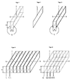
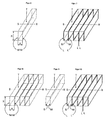
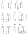
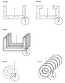
- Figures 1 to 26 show the structure of directional screens.
- FIG. 27 shows a directional aperture according to the invention.
- FIGS. 28 and 29 show a comparative aperture which is not part of the invention.
- a directional aperture with a plurality of slats (L) facing each other have parallel light wells, with the gaps filled by a carrier body (T) and the slats (L) are applied to these.
- the suitable material as a carrier for very thin slats (L) are in the range of Light, because of the low losses, acrylic glass and others Plastics, as well as special types of glass.
- the undesirable reflection effect is thereby avoided that the surface of the carrier body (T) previously is chemically or mechanically roughened, or the carrier material with a roughened surface. So that becomes a strongly diffusing effect achieved.
- the production of roughened Plastic or glass carrier bodies are made in which the Casting or injection molds for the plates or bodies made of glass, Metal, etc. are made, previously roughened. Under Roughening or matting is the application of a random Structure as e.g. created by sandblasting, understood.
- regular ones can also be used instead of random ones or planned structures can be used around the reflection conditions to influence.
- the lamellae (L) can be structured the surface of the carrier substance by various methods are applied, in particular by brush or roller, by Spraying or vapor deposition, photographically or by printing. Colors are mainly suitable as slat fabrics, but also Metals or plastics, especially suitable types of glue.
- the Carrier bodies are then joined and connected, so that usually one on the surface of a support body Half of a slat is applied.
- the diffuse effect of the structured surface can further increased by absorbent materials or colors and the diffuse reflection can be kept to a minimum.
- the reflection of slats can also (L) on carrier bodies (T) can be specifically increased by that highly reflective materials for the application of the slats (L) used on a support body (T) that is as smooth as possible become.
- highly reflective materials for the application of the slats (L) used on a support body (T) that is as smooth as possible become.
- Such materials can be metallized colors or evaporated Metals, but also foils or the like.
- each slat is composed of two sides
- each on an adjacent carrier body (T) can be applied according to the invention the different light output in a given Direction can be achieved by specular or diffuse reflecting Slat sides on the one hand and absorbent slat sides on the other hand, be combined in such a way that the radiation is targeted thrown in a certain direction.
- the lateral view is significant reduces that the surfaces of the carrier bodies (T) are formed, be it wavy or angled (jagged), which also causes the on slats to be applied (L) receive this shape.
- U-shaped carrier body T, Fig. 25 and 26
- T, Fig. 25 and 26 which in Longitudinal direction of a fluorescent tube are assembled Find application.
- a directional aperture that is optimal for the light source Protection against environmental influences granted from carrier bodies (T) put together, which are U-shaped, or which are U-shaped and have additional inward lugs on the top, open side.
- carrier bodies (T) put together which are U-shaped, or which are U-shaped and have additional inward lugs on the top, open side.
- the lamellae (L) are in turn on these carrier bodies (T) before they are put together.
Landscapes
- Physics & Mathematics (AREA)
- Engineering & Computer Science (AREA)
- General Engineering & Computer Science (AREA)
- General Physics & Mathematics (AREA)
- Optics & Photonics (AREA)
- Optical Elements Other Than Lenses (AREA)
- Overhead Projectors And Projection Screens (AREA)
- Devices For Indicating Variable Information By Combining Individual Elements (AREA)
- Switches With Compound Operations (AREA)
Description
Claims (21)
- Richtblende mit einer Mehrzahl von Lamellen (L), die zueinander parallele Strahlenschächte bilden, sowie mit transparenten Trägerkörpern (T), welche die Zwischenräume zwischen den Lamellen (L) ausfüllen, dadurch gekennzeichnet, daß sie aus U-förmigen Trägerkörpern (T) aufgebaut ist, wobei die Außenseiten dieser Trägerkörper (T) Lichtaustrittsflächen der Richtblende bilden und die Trägerkörper (T) mit den zwischen ihnen befindlichen Lamellen (L) derart zusammenwirken, daß das Licht, welches aus dem von den Trägerkörpern (T) umschlossenen Bereich auf die Trägerkörper (T) einfällt, aufgrund des Brechungsindex der Trägerkörper (T) beim Eintritt in diese zur Senkrechten zu der Einfallsfläche hin gebrochen wird und sowohl im Bereich der Basis als auch im Bereich der Schenkel der U-förmigen Trägerkörper (T) beim Durchtritt durch die Trägerkörper (T) nach außen zu der besagten Lichtaustrittsfläche hin kollimiert wird, und daß die einzelnen Lamellen auf jeder Seite eine andere Farbe oder andere Farben aufweisen.
- Richtblende nach Anspruch 1, dadurch gekennzeichnet, daß das Material der Lamellen (L) absorbierende Wirkung aufweist und dadurch die Reflexion von Licht vermindert.
- Richtblende nach Anspruch 1, dadurch gekennzeichnet, daß die Lamellen (L) aus stark reflektierendem Material, insbesondere aus metallisierten Farben oder aufgedampftem Metall hergestellt sind, das auf eine glatte oder polierte Verbund-Oberfläche (G) der Trägerkörper (T) aufgetragen wird.
- Richtblende nach einem der vorangehenden Ansprüche, dadurch gekennzeichnet, daß die einzelnen Lamellen (L) auf jeder Seite eine andere Reflexions- und/oder Absorptionseigenschaft aufweisen und diese daher geeignet ist, das Licht in eine gewünschte Richtung zu lenken.
- Richtblende nach den Ansprüchen 4 und 5, dadurch gekennzeichnet, daß die Richtblende so konstruiert ist, daß sie durch den Anwender gedreht und das ausfallende Licht damit in die gewünschte Richtung geworfen werden kann.
- Richtblende nach einem der vorangehenden Ansprüche, dadurch gekennzeichnet, daß die Flächen der einzelnen Lamellen (L) wellenförmig (Fig. 24) oder gewinkelt (Fig. 23) geformt sind und damit den seitlichen Einblick durch die Richtblende verwehren.
- Richtblende nach einem der Ansprüche 1 bis 6, dadurch gekennzeichnet, daß die U-förmigen Trägerkörper (T, Fig. 25) eine von ihnen umschlossene Lichtquelle vor Umwelteinflüssen schützen.
- Richtblende nach Anspruch 7, dadurch gekennzeichnet, daß die Trägerkörper (T), die durch ihre U-förmige Ausgestaltung die Lichtquelle umfassen und schützen, durch einen Kragen am oberen Ende der U-Form ergänzt werden, der in die U-Öffnung hineinragt, wodurch die Lichtquelle noch mehr umfaßt wird (Fig. 26).
- Richtblende nach einem der vorangehenden Ansprüche, dadurch gekennzeichnet, daß die Oberflächen der Trägerkörper (T) regelmäßig strukturiert sind, wodurch dem diffusen Licht eine Charakteristik mit einem Glanz verliehen wird (Fig. 20 und 21).
- Richtblende nach einem der vorangehenden Ansprüche, dadurch gekennzeichnet, daß für die Bildung der Lamellen (L) dünne Folien eingelegt werden.
- Richtblende nach einem der vorangehenden Ansprüche, dadurch gekennzeichnet, daß die Trägerkörper (T, Fig. 1, 6, 9, 21 und 25) aus Acryl hergestellt sind.
- Richtblende nach einem der Ansprüche 1 bis 10, dadurch gekennzeichnet, daß die Trägerkörper (T, Fig. 1, 6, 9, 21 und 25) aus Glas hergestellt sind.
- Richtblende nach einem der Ansprüche 1 bis 11, dadurch gekennzeichnet, daß die Trägerkörper (T, Fig. 1, 6, 9, 21 und 25) durch ein Spritzgußverfahren herstellbar sind.
- Richtblende nach einem der vorangehenden Ansprüche, dadurch gekennzeichnet, daß absorbierende oder reflektierende Farbstoffe, die auf dem Trägerkörper (T) die Lamellen (L) bilden, dem zur Verbindung der Trägerkörper (T) verwendeten Leim oder Klebstoff zugegeben sind.
- Richtblende nach einem der vorangehenden Ansprüche, dadurch gekennzeichnet, daß für die Bildung der Lamellen (L) lediglich die unterschiedlichen Brechungsindices zwischen dem Trägerkörper (T) und der in einem schmalen Schlitz enthaltenen Luft verwendet sind (Fig. 5 und 8).
- Verfahren zur Herstellung einer Richtblende nach einem der vorangehenden Ansprüche, dadurch gekennzeichnet, daß die Trägerkörper (T, Fig. 6) nach ihrer Herstellung an der Verbund-Oberfläche (G) aufgerauht werden oder mit rauher Verbund-Oberfläche (G) hergestellt und die Lamellen (L, Fig. 7) sodann auf diese Verbund-Oberflächen (G) aufgetragen und diese Elemente daraufhin miteinander verbunden werden (Fig. 7).
- Verfahren nach Anspruch 16, dadurch gekennzeichnet, daß die Trägerkörper (T) nach ihrer Herstellung mechanisch aufgerauht werden.
- Verfahren nach Anspruch 16, dadurch gekennzeichnet, daß die Trägerkörper (T) nach ihrer Herstellung chemisch aufgerauht werden
- Verfahren nach Anspruch 16, dadurch gekennzeichnet, daß die Gußform für die Herstellung des Trägerkörpers (T) aufgerauht wird und die darin gegossenen Trägerkörper (T) daher eine rauhe Verbund-Oberfläche (M) haben.
- Verfahren zum Herstellen einer Richtblende nach einem der Ansprüche 1 bis 15, insbesondere nach einem der Ansprüche 17 bis 19, dadurch gekennzeichnet, daß die Trägerkörper (T) im Stranggußverfahren hergestellt, zusammengeführt, verbunden und anschließend auf die entsprechende Breite oder Länge, senkrecht zur Ebene der Lamellen zugeschnitten werden.
- Verwendung einer Richtblende nach einem der Ansprüche 1 bis 15 zum Schutz einer Lichtquelle vor Umwelteinflüssen.
Applications Claiming Priority (3)
| Application Number | Priority Date | Filing Date | Title |
|---|---|---|---|
| CH3584/93 | 1993-12-01 | ||
| CH03584/93A CH690657A5 (de) | 1993-12-01 | 1993-12-01 | Richtblende für Beleuchtungskörper. |
| CH358493 | 1993-12-01 |
Publications (2)
| Publication Number | Publication Date |
|---|---|
| EP0658780A1 EP0658780A1 (de) | 1995-06-21 |
| EP0658780B1 true EP0658780B1 (de) | 2002-07-03 |
Family
ID=4259151
Family Applications (1)
| Application Number | Title | Priority Date | Filing Date |
|---|---|---|---|
| EP94118755A Expired - Lifetime EP0658780B1 (de) | 1993-12-01 | 1994-11-29 | Richtblende für Beleuchtungskörper und Verfahren zu deren Herstellung |
Country Status (7)
| Country | Link |
|---|---|
| US (1) | US5570239A (de) |
| EP (1) | EP0658780B1 (de) |
| AT (1) | ATE220211T1 (de) |
| CA (1) | CA2136664A1 (de) |
| CH (1) | CH690657A5 (de) |
| DE (1) | DE59410148D1 (de) |
| ES (1) | ES2181699T3 (de) |
Families Citing this family (16)
| Publication number | Priority date | Publication date | Assignee | Title |
|---|---|---|---|---|
| DE29716999U1 (de) * | 1997-09-23 | 1998-01-08 | Semperlux GmbH Lichttechnisches Werk, 12277 Berlin | Prismierte Lamellen zur Abblendung und Lenkung von Licht |
| DE19941028A1 (de) * | 1999-08-28 | 2001-04-05 | Willing Gmbh Dr Ing | Beleuchtungsvorrichtung mit blattförmiger Lichtverteilung zur Oberflächeninspektion |
| US7284881B2 (en) * | 2004-03-31 | 2007-10-23 | Ledo Co., Ltd. | LED fixing device of a pixel module and method for manufacturing the same |
| CA2568918A1 (en) * | 2004-04-06 | 2005-10-20 | John Warwick Ellemor | Light absorbing elements |
| ITMI20050625A1 (it) * | 2005-04-13 | 2006-10-14 | Reggiani Illuminazione | Apparecchio di illuminazione con schermo perfezionato |
| DE102007017343B4 (de) * | 2007-04-12 | 2010-05-12 | Airbus Deutschland Gmbh | Leseleuchte mit Streulichtunterdrückung |
| WO2008155767A2 (en) | 2007-06-20 | 2008-12-24 | T C View Ltd | Methods systems and devices for utilizing directions of light rays |
| ITVI20070290A1 (it) * | 2007-10-31 | 2009-05-01 | Turn Lights S R L | Struttura di schermo, particolarmente per apparecchi di illuminazione. |
| DE102007057691B4 (de) * | 2007-11-30 | 2018-01-18 | Siteco Beleuchtungstechnik Gmbh | Blende für eine Leuchte |
| US8601757B2 (en) * | 2010-05-27 | 2013-12-10 | Solatube International, Inc. | Thermally insulating fenestration devices and methods |
| KR101117707B1 (ko) * | 2010-10-12 | 2012-02-29 | 삼성에스디아이 주식회사 | 광 투과도 조절막, 광 투과도 조절 유리, 및 창호용 유리 |
| ITVR20120062A1 (it) * | 2012-03-29 | 2013-09-30 | Fabio Falchi | Sistema di limitazione della diffusione della luce |
| USD711037S1 (en) * | 2013-04-19 | 2014-08-12 | Cooper Technologies Company | Open frame edgelit high bay luminaire |
| US20160124126A1 (en) | 2014-10-29 | 2016-05-05 | Sergiy Vasylyev | Angular selective light control sheeting and method of making the same |
| DE102016117262A1 (de) | 2016-09-14 | 2018-03-15 | Khs Gmbh | Vorrichtung und Verfahren zur telezentrischen Inspektion eines Objekts |
| DE102017003517A1 (de) * | 2017-04-11 | 2018-10-11 | Universität Hamburg | Verfahren und Messvorrichtung zur Röntgenfluoreszenz-Messung |
Citations (4)
| Publication number | Priority date | Publication date | Assignee | Title |
|---|---|---|---|---|
| US1654874A (en) * | 1925-07-11 | 1928-01-03 | Gussalli Luigi | Screen for sun cures |
| US2258354A (en) * | 1940-08-03 | 1941-10-07 | Doane Products Corp | Luminaire |
| US3894228A (en) * | 1973-09-24 | 1975-07-08 | Minnesota Mining & Mfg | Light control device |
| US4630181A (en) * | 1985-07-15 | 1986-12-16 | H. E. Williams, Inc. | Fluorescent lighting fixture |
Family Cites Families (15)
| Publication number | Priority date | Publication date | Assignee | Title |
|---|---|---|---|---|
| US2212793A (en) * | 1937-09-13 | 1940-08-27 | Rex Walter James | Antidazzle device |
| US2467096A (en) * | 1945-02-09 | 1949-04-12 | Paul M Ressinger | Illuminating device |
| FR1334217A (fr) * | 1962-09-24 | 1963-08-02 | Dow Chemical Co | Feuilles de composition thermoplastique transparente qui diffusent la lumière |
| DE2914682C3 (de) * | 1979-04-11 | 1982-05-13 | Schott Glaswerke, 6500 Mainz | Verfahren zur Herstellung einer als Lichtblende wirkenden Glasplatte und nach diesem Verfahren hergestellte Glasplatte |
| US4621898A (en) * | 1983-03-17 | 1986-11-11 | Allied Corporation | Directional optical filter |
| US4533210A (en) * | 1983-05-24 | 1985-08-06 | Incom, Inc. | Optical fiber light filter using elongated radiation absorbing elements |
| US4553818A (en) * | 1983-12-12 | 1985-11-19 | Allied Corporation | Directional filter for filtering ambient light |
| JPS60195849A (ja) * | 1984-03-19 | 1985-10-04 | Asahi Chem Ind Co Ltd | 遮光スクリ−ンの製造方法 |
| US4877308A (en) * | 1987-06-24 | 1989-10-31 | Asahi Kasei Kogyo Kabushiki Kaisha | Light shielding screen structure and a process for producing the same |
| NZ224424A (en) * | 1987-11-06 | 1990-12-21 | Ian Robert Edmonds | Light deflecting window panel: parallel cuts in transparent material by laser |
| EP0354672A3 (de) * | 1988-08-08 | 1990-10-10 | Minnesota Mining And Manufacturing Company | Lichtkollimierender Film |
| DE3932935A1 (de) * | 1989-10-03 | 1991-04-11 | Zumtobel Ag | Leuchtenraster |
| US5008791A (en) * | 1990-07-19 | 1991-04-16 | Caferro Ronald N | Low direct glare and wall wash parabolic lighting grid |
| AU649298B2 (en) * | 1990-12-21 | 1994-05-19 | Minnesota Mining And Manufacturing Company | Light control film with reduced ghost images |
| US5149191A (en) * | 1991-12-23 | 1992-09-22 | Ian Lewin | Combination louver/lens light fixture shield |
-
1993
- 1993-12-01 CH CH03584/93A patent/CH690657A5/de not_active IP Right Cessation
-
1994
- 1994-11-02 US US08/332,791 patent/US5570239A/en not_active Expired - Fee Related
- 1994-11-25 CA CA002136664A patent/CA2136664A1/en not_active Abandoned
- 1994-11-29 AT AT94118755T patent/ATE220211T1/de not_active IP Right Cessation
- 1994-11-29 DE DE59410148T patent/DE59410148D1/de not_active Expired - Fee Related
- 1994-11-29 ES ES94118755T patent/ES2181699T3/es not_active Expired - Lifetime
- 1994-11-29 EP EP94118755A patent/EP0658780B1/de not_active Expired - Lifetime
Patent Citations (4)
| Publication number | Priority date | Publication date | Assignee | Title |
|---|---|---|---|---|
| US1654874A (en) * | 1925-07-11 | 1928-01-03 | Gussalli Luigi | Screen for sun cures |
| US2258354A (en) * | 1940-08-03 | 1941-10-07 | Doane Products Corp | Luminaire |
| US3894228A (en) * | 1973-09-24 | 1975-07-08 | Minnesota Mining & Mfg | Light control device |
| US4630181A (en) * | 1985-07-15 | 1986-12-16 | H. E. Williams, Inc. | Fluorescent lighting fixture |
Also Published As
| Publication number | Publication date |
|---|---|
| US5570239A (en) | 1996-10-29 |
| DE59410148D1 (de) | 2002-08-08 |
| ES2181699T3 (es) | 2003-03-01 |
| EP0658780A1 (de) | 1995-06-21 |
| ATE220211T1 (de) | 2002-07-15 |
| CH690657A5 (de) | 2000-11-30 |
| CA2136664A1 (en) | 1995-06-02 |
Similar Documents
| Publication | Publication Date | Title |
|---|---|---|
| EP0846915B1 (de) | Innenraumleuchte | |
| EP2344362B1 (de) | Lichtleitelement für eine beleuchtungseinrichtung | |
| WO2004007887A1 (de) | Fensterelement | |
| EP1110031B1 (de) | Leuchte mit lichtleitelement | |
| EP0658780A1 (de) | Richtblende für Beleuchtungskörper und Verfahren zu deren Herstellung | |
| EP0533301B1 (de) | Hinweisleuchte | |
| EP0191264B1 (de) | Einrichtung zum Entblenden von grossflächigen Leuchtmitteln | |
| DE102004002251A1 (de) | Leuchte mit verschiedenfarbigen Lichtquellen sowie einer Lichtleiterplatte zum Abgeben von Mischlicht | |
| EP1132680A1 (de) | Leuchte mit inhomogener Lichtabstrahlung | |
| DE69627744T2 (de) | Farbiges Lichtbündel erzeugende und beim ausgeschalteten Zustand andersfarbige Signalleuchte, insbesondere für Kraftfahrzeuge und Verfahren zum Herstellen ihrer Lichtscheibe | |
| EP1608909B1 (de) | Lichtbeeinflussungselement | |
| DE29710475U1 (de) | Innenleuchte | |
| DE4312889A1 (de) | Vorwiegend direkt strahlende Leuchte mit einem abgehängten Lichtleitkörper | |
| DE4215968A1 (de) | Lichtlenkende Struktur zum Beleuchten eines Raumes mit Tageslicht | |
| EP0372272A1 (de) | Spiegelrasterleuchte | |
| DE3420414C2 (de) | Lichtdurchlässige Leuchtenabdeckung zur Entblendung von Leuchten mit langgestreckten Lampen | |
| DE29712314U1 (de) | Innenleuchte | |
| EP1685348B2 (de) | Leuchte mit transparentem lichtaustrittselement | |
| DE19853811A1 (de) | Signalleuchte mit kontrollierter Beleuchtungsstärke des Leuchtfelds und Verfahren zur Herstellung eines Kolbens für eine derartige Leuchte | |
| DE10354462B4 (de) | Leuchte mit asymmetrischer Lichtabstrahlung | |
| DE29903847U1 (de) | Lichtleitelement für Beleuchtungsanordnung zur Raumbeleuchtung | |
| DE102017129505A1 (de) | LED-Band | |
| DE10301257A1 (de) | Leuchte mit einer Abdeckscheibe mit verringerter Reflexion | |
| DE29724321U1 (de) | Beleuchtungseinrichtung | |
| DE10324852A1 (de) | Tageslichtbeleuchtungssystem |
Legal Events
| Date | Code | Title | Description |
|---|---|---|---|
| PUAI | Public reference made under article 153(3) epc to a published international application that has entered the european phase |
Free format text: ORIGINAL CODE: 0009012 |
|
| AK | Designated contracting states |
Kind code of ref document: A1 Designated state(s): AT BE DE ES FR GB IE IT NL |
|
| 17P | Request for examination filed |
Effective date: 19951123 |
|
| 17Q | First examination report despatched |
Effective date: 19980324 |
|
| GRAG | Despatch of communication of intention to grant |
Free format text: ORIGINAL CODE: EPIDOS AGRA |
|
| GRAG | Despatch of communication of intention to grant |
Free format text: ORIGINAL CODE: EPIDOS AGRA |
|
| GRAH | Despatch of communication of intention to grant a patent |
Free format text: ORIGINAL CODE: EPIDOS IGRA |
|
| GRAH | Despatch of communication of intention to grant a patent |
Free format text: ORIGINAL CODE: EPIDOS IGRA |
|
| GRAA | (expected) grant |
Free format text: ORIGINAL CODE: 0009210 |
|
| AK | Designated contracting states |
Kind code of ref document: B1 Designated state(s): AT BE DE ES FR GB IE IT NL |
|
| PG25 | Lapsed in a contracting state [announced via postgrant information from national office to epo] |
Ref country code: NL Free format text: LAPSE BECAUSE OF FAILURE TO SUBMIT A TRANSLATION OF THE DESCRIPTION OR TO PAY THE FEE WITHIN THE PRESCRIBED TIME-LIMIT Effective date: 20020703 Ref country code: IE Free format text: LAPSE BECAUSE OF FAILURE TO SUBMIT A TRANSLATION OF THE DESCRIPTION OR TO PAY THE FEE WITHIN THE PRESCRIBED TIME-LIMIT Effective date: 20020703 |
|
| REF | Corresponds to: |
Ref document number: 220211 Country of ref document: AT Date of ref document: 20020715 Kind code of ref document: T |
|
| REG | Reference to a national code |
Ref country code: IE Ref legal event code: FG4D Free format text: GERMAN |
|
| REF | Corresponds to: |
Ref document number: 59410148 Country of ref document: DE Date of ref document: 20020808 |
|
| GBT | Gb: translation of ep patent filed (gb section 77(6)(a)/1977) |
Effective date: 20021007 |
|
| NLV1 | Nl: lapsed or annulled due to failure to fulfill the requirements of art. 29p and 29m of the patents act | ||
| PGFP | Annual fee paid to national office [announced via postgrant information from national office to epo] |
Ref country code: GB Payment date: 20021204 Year of fee payment: 9 |
|
| PGFP | Annual fee paid to national office [announced via postgrant information from national office to epo] |
Ref country code: FR Payment date: 20021210 Year of fee payment: 9 |
|
| PGFP | Annual fee paid to national office [announced via postgrant information from national office to epo] |
Ref country code: AT Payment date: 20021211 Year of fee payment: 9 |
|
| PGFP | Annual fee paid to national office [announced via postgrant information from national office to epo] |
Ref country code: DE Payment date: 20021227 Year of fee payment: 9 |
|
| PGFP | Annual fee paid to national office [announced via postgrant information from national office to epo] |
Ref country code: ES Payment date: 20021230 Year of fee payment: 9 |
|
| ET | Fr: translation filed | ||
| PGFP | Annual fee paid to national office [announced via postgrant information from national office to epo] |
Ref country code: BE Payment date: 20030117 Year of fee payment: 9 |
|
| REG | Reference to a national code |
Ref country code: ES Ref legal event code: FG2A Ref document number: 2181699 Country of ref document: ES Kind code of ref document: T3 |
|
| REG | Reference to a national code |
Ref country code: IE Ref legal event code: FD4D Ref document number: 0658780E Country of ref document: IE |
|
| PLBE | No opposition filed within time limit |
Free format text: ORIGINAL CODE: 0009261 |
|
| STAA | Information on the status of an ep patent application or granted ep patent |
Free format text: STATUS: NO OPPOSITION FILED WITHIN TIME LIMIT |
|
| 26N | No opposition filed |
Effective date: 20030404 |
|
| PG25 | Lapsed in a contracting state [announced via postgrant information from national office to epo] |
Ref country code: GB Free format text: LAPSE BECAUSE OF NON-PAYMENT OF DUE FEES Effective date: 20031129 Ref country code: AT Free format text: LAPSE BECAUSE OF NON-PAYMENT OF DUE FEES Effective date: 20031129 |
|
| PG25 | Lapsed in a contracting state [announced via postgrant information from national office to epo] |
Ref country code: BE Free format text: LAPSE BECAUSE OF NON-PAYMENT OF DUE FEES Effective date: 20031130 |
|
| PG25 | Lapsed in a contracting state [announced via postgrant information from national office to epo] |
Ref country code: ES Free format text: LAPSE BECAUSE OF NON-PAYMENT OF DUE FEES Effective date: 20031201 |
|
| BERE | Be: lapsed |
Owner name: *RAIMONDI BRUNO Effective date: 20031130 Owner name: *RAIMONDI-STAEUBLE OLGA Effective date: 20031130 Owner name: *RAIMONDI ENRICO Effective date: 20031130 |
|
| PG25 | Lapsed in a contracting state [announced via postgrant information from national office to epo] |
Ref country code: DE Free format text: LAPSE BECAUSE OF NON-PAYMENT OF DUE FEES Effective date: 20040602 |
|
| GBPC | Gb: european patent ceased through non-payment of renewal fee |
Effective date: 20031129 |
|
| PG25 | Lapsed in a contracting state [announced via postgrant information from national office to epo] |
Ref country code: FR Free format text: LAPSE BECAUSE OF NON-PAYMENT OF DUE FEES Effective date: 20040730 |
|
| REG | Reference to a national code |
Ref country code: FR Ref legal event code: ST |
|
| REG | Reference to a national code |
Ref country code: ES Ref legal event code: FD2A Effective date: 20031201 |
|
| PG25 | Lapsed in a contracting state [announced via postgrant information from national office to epo] |
Ref country code: IT Free format text: LAPSE BECAUSE OF NON-PAYMENT OF DUE FEES Effective date: 20051129 |