EP0658896A2 - Gerät und Methoden zur Verbesserung der Datenermittlungverlässlichkeit - Google Patents
Gerät und Methoden zur Verbesserung der Datenermittlungverlässlichkeit Download PDFInfo
- Publication number
- EP0658896A2 EP0658896A2 EP94119393A EP94119393A EP0658896A2 EP 0658896 A2 EP0658896 A2 EP 0658896A2 EP 94119393 A EP94119393 A EP 94119393A EP 94119393 A EP94119393 A EP 94119393A EP 0658896 A2 EP0658896 A2 EP 0658896A2
- Authority
- EP
- European Patent Office
- Prior art keywords
- preselected
- data
- boundary
- values
- count
- Prior art date
- Legal status (The legal status is an assumption and is not a legal conclusion. Google has not performed a legal analysis and makes no representation as to the accuracy of the status listed.)
- Withdrawn
Links
- 238000001514 detection method Methods 0.000 title claims abstract description 14
- 238000000034 method Methods 0.000 title claims description 46
- 238000012545 processing Methods 0.000 claims abstract description 17
- 238000012886 linear function Methods 0.000 claims abstract description 15
- 238000013500 data storage Methods 0.000 claims description 8
- 230000001143 conditioned effect Effects 0.000 claims description 3
- 238000005259 measurement Methods 0.000 claims description 2
- 238000003860 storage Methods 0.000 claims description 2
- 230000000977 initiatory effect Effects 0.000 claims 2
- 238000007476 Maximum Likelihood Methods 0.000 abstract description 19
- 230000008569 process Effects 0.000 description 12
- 230000005291 magnetic effect Effects 0.000 description 10
- 230000007704 transition Effects 0.000 description 9
- 230000004044 response Effects 0.000 description 7
- 238000010586 diagram Methods 0.000 description 6
- 230000014509 gene expression Effects 0.000 description 5
- 238000004364 calculation method Methods 0.000 description 4
- 238000012360 testing method Methods 0.000 description 4
- 239000013598 vector Substances 0.000 description 4
- 230000008859 change Effects 0.000 description 3
- 238000013459 approach Methods 0.000 description 2
- 230000008901 benefit Effects 0.000 description 2
- 230000007423 decrease Effects 0.000 description 2
- 230000001419 dependent effect Effects 0.000 description 2
- 101001062854 Rattus norvegicus Fatty acid-binding protein 5 Proteins 0.000 description 1
- 239000000654 additive Substances 0.000 description 1
- 230000000996 additive effect Effects 0.000 description 1
- 238000004458 analytical method Methods 0.000 description 1
- 238000013100 final test Methods 0.000 description 1
- 230000006872 improvement Effects 0.000 description 1
- 238000004519 manufacturing process Methods 0.000 description 1
- 230000004048 modification Effects 0.000 description 1
- 238000012986 modification Methods 0.000 description 1
- 238000005457 optimization Methods 0.000 description 1
- 238000011084 recovery Methods 0.000 description 1
- 238000005070 sampling Methods 0.000 description 1
- 238000012800 visualization Methods 0.000 description 1
Images


Classifications
-
- G—PHYSICS
- G11—INFORMATION STORAGE
- G11B—INFORMATION STORAGE BASED ON RELATIVE MOVEMENT BETWEEN RECORD CARRIER AND TRANSDUCER
- G11B20/00—Signal processing not specific to the method of recording or reproducing; Circuits therefor
- G11B20/10—Digital recording or reproducing
- G11B20/10009—Improvement or modification of read or write signals
-
- G—PHYSICS
- G11—INFORMATION STORAGE
- G11B—INFORMATION STORAGE BASED ON RELATIVE MOVEMENT BETWEEN RECORD CARRIER AND TRANSDUCER
- G11B20/00—Signal processing not specific to the method of recording or reproducing; Circuits therefor
- G11B20/10—Digital recording or reproducing
- G11B20/14—Digital recording or reproducing using self-clocking codes
- G11B20/1403—Digital recording or reproducing using self-clocking codes characterised by the use of two levels
- G11B20/1423—Code representation depending on subsequent bits, e.g. delay modulation, double density code, Miller code
- G11B20/1426—Code representation depending on subsequent bits, e.g. delay modulation, double density code, Miller code conversion to or from block codes or representations thereof
Definitions
- This invention relates to apparatus and methods for improving data detection reliability in a coded signal processing channel by determining and setting optimal values for threshold constants constituting decision boundaries for interpreting sample values representative of coded binary data.
- Each of the References 1-3 discloses a (1,7) ML decoder which uses a differing number of look-ahead digital sample values f derived from an analog read signal to execute several decisions for implementing a maximum likelihood (ML) decision.
- An ML decision involves comparing each of several linear functions H of the sample values y to the value of a threshold constant constituting a ML decision boundary related to that linear function.
- the linear functions and decision boundaries are chosen to minimize the overall mean square error in a ML sequence detection process using five, six, or eight look-ahead sample values of the read signal, as taught in References 1, 2, and 3, respectively.
- Each Reference 1-3 discloses equations by which the decoder can compute nominal theoretical values of a set of boundary threshold constants from information about the shape of the analog pulse that is read back from the analog pulse transmitted over the (1,7) ML channel.
- boundary threshold constants are generated from the readback pulse corresponding to a single transition. This assumes that the positive or negative readback pulse has a single form which can be described by three non-zero sample values.
- these computed thresholds may not be optimal because in reality signal processing channels are subject to nonlinearity, misequalization, and pulse asymmetry, in addition to pattern-dependent noise.
- Reference 4 describes a five-sample look-ahead algorithm, including a geometrical interpretation of the decision algorithm. Boundary constants are determined from formulae related to the pulse shape response for a single magnetic transition, as in References 1-3.
- None of these references discloses or suggests (i) determining nominal values of the threshold constants from a statistically significant number of readback pulse transitions that account for nonlinearity, misequalization, pulse asymmetry and pattern-dependent noise, and (ii) treating as potential errors in the detected data those which are too close to a selected threshold boundary, and automatically adjusting each threshold boundary so that a substantially equal number of error events occur at each side thereof.
- the present invention has the object to overcome the above drawbacks.
- a plurality of threshold constants whose values define decision boundaries are used in determining whether detected data corresponding to a coded sequence of a runlength limited (RLL) code is a "1" or a "0". If desired, boundary adjustment may be performed dynamically during a time-out between consecutive read operations or during a read operation.
- RLL runlength limited
- two known preselected data patterns of the digital sample values are identified that are determined to be closest above and closest below, respectively, said boundary.
- Actual values of linear functions of the digital sample values corresponding to multiple occurrences of these two data patterns are preferably collected on a decision boundary plot to permit visualization of the decision process.
- Clusters are formed of actual values of the one data pattern above and the other data pattern below the decision boundary.
- a focal point is determined for each of the two clusters and the threshold constant for the preselected decision boundary is established substantially midway between such focal points, provided the actual values in both of said clusters exceeds a preselected sufficient number, and then loaded in a boundary register.
- the threshold constant for the selected boundary After the initial value of the threshold constant for the selected boundary has been determined, it is adjusted to an optimal value by either of two methods. In each method, separate counters count as potential error events in the detected data those which are determined to be both above and below a selected one of the decision boundaries as a result of a "1" being potentially misdetected as a "0" (corresponding to an N pattern being potentially misinterpreted as an M pattern), and vice versa.
- the selected decision boundary is adjusted in a direction toward providing a substantially equal number of potential error events at each side of that boundary.
- a multiplexor enables selection of the particular boundary to be evaluated and adjusted.
- an error margin distance (MD) is computed which represents the difference between a boundary threshold constant and H ' outputs representing actual values of the aforesaid linear functions.
- MD error margin distance
- a selected one of the decision boundaries is intentionally moved upward m. units and then downward m units from an initial preselected position to determine the number of potential error events on each side and to determine if and how the boundary should be adjusted.
- Fig. 1 is a schematic diagram of a coded digital signal processing channel, as known in the prior art.
- Fig. 2 depicts ideal write and read waveforms for (1,7) ML coded data and read sample values, as heretofore known.
- Fig. 3 is a boundary plot diagram for one type of peak position check for state 000, as known in the prior art.
- Fig. 4 is a boundary plot diagram for a modified peak position check for state 000, as known in the prior art.
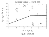
- Fig. 5 is a boundary plot diagram for a baseline check for state 000, as known In the prior art.
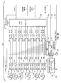
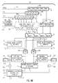
- Figs. 6A and 6B when taken together, constitute a schematic diagram of a decoder apparatus embodying the invention and comprising a six-sample look-ahead feature and means for setting decision boundaries at optimal values in the coded digital signal processing channel of Fig. 1.
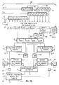
- Figs. 7A and 7B when taken together, constitute a schematic diagram that depicts a modification of the decoder apparatus illustrated in Figs. 6A and 6B to show a variation of the manner in which the invention may be implemented.
- Fig. 1 depicts, as known in the prior art, a coded digital signal processing channel, preferably an extended partial response maximum likelihood (EPRML) channel which is characterized by the polynomial (1-D)(1+D)2 .
- An analog signal is read by a transducer 8 from a magnetic recording medium, such as a disk 9, in a digital storage device.
- This read signal corresponds to a binary data sequence coded with the (1,7) run length limited (RLL) code during a write operation.
- the read signal passes from line 10 through a preamplifier 11 with automatic gain control (AGC) and a low bandpass filter 12.
- AGC automatic gain control
- the output of filter 12 is supplied to a phase-locked clock 13 comprising a phase-locked loop timing recovery circuit including a variable frequency oscillator (VFO).
- VFO variable frequency oscillator
- Filter 12 and equalizer 22 filter the read signal so that the response to a single magnetic transition is a pulse given by the sample values ..., 0, 2, 4, 2, 0, ... . This results in written transitions of magnitude 2 between +1 and -1 levels of magnetic saturation, and read response is normalized by a scaling factor to correspond thereto.
- the coded analog read signal output from filter 12 is supplied to a delay means 20.
- Delay means 20 provides delay alignment between the analog signal and clock signal inputs to an analog-to-digital converter (ADC) 21.
- ADC 21 converts the analog input signal into digital sample values, such as y0...y5, at successive clock times, where y0 corresponds to the current clock cycle.
- These digital sample values are then passed to a decoder 23. Positive and negative boundary threshold constants are applied via lines 24, 25, respectively, to decoder 23.
- Decoder 23 applies a decoding algorithm to the digital sample values to provide a coded binary data output in line 26 and, where appropriate, a pointer flag in line 27, at successive clock times under control of clock 13.
- Fig. 2 depicts the write and read waveforms and associated sequences of data and sample values clocked by clock 13 in a noise-free environment.
- the sample values range through the discrete set ⁇ -4, -2, 0, +2, +4 ⁇ .
- Actual samples will not be exactly equal to the ideal patterns of the read signal because of signal anomalies due to nonlinearity, misequalization, and/or pulse asymmetry, as well as additive noise, and thus will range through various noninteger values around the integers in the discrete set.
- y ⁇ x ⁇ +e ⁇ where x ⁇ is exactly equal to one of the ideal patterns, and e ⁇ is the error in the received signal.
- the (1,7) ML decoding algorithm decides which of the ideal patterns is closest to the actual received pattern.
- the (1,7) ML channel will be in one of six states: 000, 100, 111, 011, 001, or 110.
- States 100, 000, and 001 correspond to detection of a positive read pulse and have mirror image (i.e., +/- sign) symmetry with states 011, 111, and 110, respectively, that correspond to detection of a negative read pulse.
- the current state is determined by past decoding decisions, and the current decoding decision determines which state comes next.
- Two of these states (001 and 110) are transitional only as the decision is automatic because the (1,7) code constraint implies that state 001 must be followed by state 011 and similarly state 110 must be followed by state 100.
- the channel must make a ML decision regarding the next state.
- each decision of the (1,7) ML algorithm requires six linear functions, H1, H2, H3, H4, H5, H6, of the sample values y0, y1, y2, y3, y4, y5, to be computed and compared to six thresholds A, B, X, Y, Z and W as established by the boundary threshold constants.
- the A and B boundaries are for a baseline check, and the X, Y, Z and W boundaries are for a peak position check, as shown in Table 1.
- Table 1 Table 1, and all other tables, are included in an Appendix hereto which is made part hereof.
- H3 is compared to two different boundary thresholds X and Y.
- the set used for each ML decision depends on the current state.
- An error is associated with the value of at least one of the functions H1 falling on the wrong side of its boundary threshold.
- the decision process can be represented geometrically by the graphs shown in Figs. 3, 4, and 5.
- Each graph contains a line defining a boundary line between N patterns above the line and M patterns below the line.
- the points, as plotted in Figs. 3, 4 and 5, correspond to the ideal patterns.
- the location of each boundary line segment is determined by a corresponding boundary threshold constant.
- the functions H i (y ⁇ ) are computed and plotted on the appropriate graphs. If a point falls on the wrong side of the boundary, an error occurs.
- the apparatus embodying the invention comprises a decoder 300 which replaces the prior art decoder 23 depicted in Fig. 1 and constitutes an improvement over the decoders disclosed in Reference 2.
- the following description has been limited to that considered necessary for an understanding of the embodiments of the present invention. For additional background description, the reader is referred to Reference 2.
- ck will be used to designate the clock input from a common source that is required in order to provide the necessary timing for the various registers hereinafter described.
- each of the 24 boundary threshold constants of the (1,7) ML decoder 300 is determined and separately and independently optimized to minimize the possibility of decoding errors.
- Two types of decoding errors can occur: (1) misdecoding an N pattern as an M pattern, which causes a "1" to be misdetected as a "0" in the detected (1,7) sequence; and (2) misdecoding an M pattern as an N pattern, which causes a "0" to be misdetected as a "1” in the detected (1,7) sequence.
- Adjusting the boundary threshold decreases the likelihood of one type of error but increases the likelihood of the other type of error.
- Table 3 shows the six different types of boundary thresholds (A, B, X, Y, Z, W) that are to be optimized for the four different states (000, 100, 111, 011) for a total of 24 boundary types.
- W2 denotes a boundary that corresponds to the state 000 or 111; the superscript '+' clarifies that the data pattern is generated by a positive read phase and therefore W2+ identifies the state as 000 rather than 111; and prefix K in KW2+ denotes that the boundary has a preselected, but adjustable, constant value. Since each boundary threshold is optimized separately and independently, the methods and apparatus for optimizing the threshold value KW2+ of only one boundary, the W2+ boundary, will be described with the understanding that all other boundaries are optimized in a similar manner. Hereafter, the "+" superscript will be dropped for simplification; and this boundary will hereinafter be referred to simply as W2 and its threshold value as KW2.
- This Section I describes how an initial value for a decision-boundary-constituting threshold constant for a (1,7) ML channel may be determined without requiring pulse sampling and calculation of a nominal value based upon the pulse shape of the read response to a single magnetic recording transition. It requires use of a known sequence of detected data.
- a given data pattern (eg., N2) has been shown as a single point.
- a given data pattern (eg., N2) has been shown as a single point.
- the cluster of points generated by the actual values for a given data pattern will hereinafter be referred to as a "cloud.”
- Each cluster of points or cloud is resolved into a respective single point hereinafter referred to as the "focal point.”
- This focal point may, for example, be determined as the mean or average of the actual values of points in each cluster, or a selected subset of the actual values of points in each cluster, to implement this method in the manner now to be described.
- the pseudo-random sequence should be preceded and followed by a one byte pad of zeroes, which are not decoded.
- the state vector s ⁇ (s1,s2,...s2) is computed, where s1 is the state a i b i c i of the channel at the time that the i th sample is being decoded, assuming that prior decoding decisions were correct.
- the average value of each function H1--H5 in the left column of Table 1 is computed for each pattern or set of patterns in the columns on the right.
- H1(y ⁇ j ) The occurrences of these values of H1(y ⁇ j ) are counted by suitable means (not shown) and, if desired, displayed on a screen to show the sample size for each cloud or set of clouds, to alert the user if there is an insufficient number of samples to determine any threshold.
- KA s [ H 1( N1 s , ⁇ N1 s ) ⁇ + H 1( M1 s , ⁇ M2 s , ⁇ M3 s ) ⁇ ]/2.
- KB s [ H 2( N4 s , ⁇ N5 s ) ⁇ + H 2( M1 s , ⁇ M2 s ) ⁇ ]/2.
- KX s [ H 3( N1 s , ⁇ N2 s ) ⁇ + H 3( M6 s , ⁇ M7 s ) ⁇ ]/2.
- KY s [ H 3( N3 s ) ⁇ + H 3( M8 s ) ⁇ ]/2.
- KZ s [ H 4( N1 s ) ⁇ + H 4( M8 s ) ⁇ ]/2.
- KW s [ H 5( N2 s ) ⁇ + H 4( M8A s ) ⁇ ]/2.
- Table 4 sets forth an APL program listing to perform the calculations described above.
- D17 is the binary vector of data which was written to the disk, and Y is the corresponding analog readback signal. Y and D17 have above been referred to as y ⁇ and d ⁇ , respectively.
- KPOS (A000, B000, X000, Y000, Z000, W000, A100 B100, X100, Y100, Z100, W100)
- KNEG (A111, B111, X111, Y111, Z111, W111, A011 B011, X0111, Y011, Z011, W011)
- the program contains one loop, in lines 12-46, which is executed once for each of the four states, 000, 100, 111, 011, with the variable T used to indicate the state for which thresholds are being computed.
- Lines 11, 14 and 22-25 compute the variable E, which contains the locations, within D17, where the channel is in state T.
- Lines 16-20 compute the H i functions, as defined in Table 7, for every six-tuple (y j , y j+1 , y j+2 , y j+3 , y j+4 , y j+5 ), within the vector Y .
- Lines 27-36 compute the locations, within D17, where the channel is in state T, and the next six data points form one of the patterns indicated in the cogent on the right side of the line.
- the sample size for each pattern or set of patterns is collected in the variable S.
- Lines 40-45 compute the thresholds for state T, using the equations given in Section 1 of Table 5.
- Each threshold constant preferably is initially determined by use of the focal point method just described; or, if desired, it may be calculated and set at a nominal theoretical value as taught in the prior art. The value or setting of the threshold constant is then optimized.
- the boundary threshold is set at a point where potential error events in each direction, upward and downward, are substantially balanced.
- inputs H1-H6 represent precomputed linear functions of digital sample values y0-y5 corresponding to multiple occurrences of one preselected N data pattern and another preselected M data pattern. They preferably are generated in precisely the same manner as shown and described in connection with Fig. 4 of Reference 2. Hence, the manner in which they are generated will not here be shown or described. Note that input H6 for computing the boundary P for the phase check is not relevant to the present invention.
- six sign change blocks 302-307 change the sign of the incoming binary number H1-H6 whenever the c0 bit in a state register 310 has the value "1", which corresponds to states 001 and 111 in the negative phase of the sampled read signal.
- the outputs H1 -H6 from the respective sign change blocks 302-307 and also the initial boundary threshold constants KA1...KW2 (previously loaded via bus IB into boundary-threshold-value register 308) are fed in parallel to a set of subtractors.
- Subtractors 312-324 compute differences between an H ' output and a related boundary threshold prefixed K to provide an output prefixed D representing an error margin distance MD. This distance MD is fed to a related one of the comparators 330-342 which, by comparing the MD to zero, determines whether the value of H ' is above or below the threshold boundary.
- the output from the subtractor 312 can be used as a measure of available margin to a potential error event, called margin distance MD.
- the outputs from the comparators 330-342 are values "1" or "0", which, together with the state values a0, b0, c0 from state register 310, are fed to the logic block 349 for implementing the logic shown in Table 5.
- the logic of block 349 provides the detected data d0 corresponding to state a0b0c0 and the erasure pointer P in accordance with the logic of Section 1 of Table 5.
- Block 349 also creates the state values a1b1c1 for the next state in accordance with the logic of Section 3 of Table 5 including the intermediate logic of Section 2 thereof. This state value is supplied to state register 310 to become the current state value a0b0c0 for the next clock cycle.
- the error margin distances MDs are available for all boundaries as outputs of the subtractors 312-324.
- Multiplexor (MUX) 345 responds to a boundary select signal in line 346 from a test controller 347 to select and output to line 348 one of the error margin distances DA11...DW21, to be examined for a boundary threshold of interest.
- MUX 345 will output DW21 for the boundary W2 to line 348.
- the outputs b1, d1, DW21 of Fig. 6A are used to implement the boundary adjustment process.
- Fig 6B depicts the state of the system five clock cycles later, relative to Fig. 6A, and so these outputs are labeled b6, d6 and DW26, respectively, in Fig. 6B.
- the d and b outputs which are binary, are fed into a seven-bit shift register 350 and a five-bit shift register 352, respectively.
- the DW2 values which are numerical values, such as in bytes, are fed into a five-byte shift register 354.
- comparators 356 and 358 in combination with the logic of Tables 6 and 7, generate, at each clock cycle, four binary values D above , D below , W above and W below which are stored in single-bit registers similarly designated. These binary values are used to increment a set of five counters, denoted T A , T B , M A , M B and C, respectively. Initially each of these counters is set to zero by a signal in reset line R. Then they are updated at each cycle.
- Comparators 356 and 358 compare the error margin distance value DW21 to a predetermined constant m to determine whether it is within m units above or below the boundary, respectively.
- the binary values D above and D below are computed as It is also necessary to process the values of d ⁇ 1 and b1 which are combined in block 351 in one logical expression to indicate if the system was in the desired state (here assumed as 000) while d1 was being detected.
- the values of d0...d5 are concurrently combined in block 351 into two different logical expressions which respectively indicate each occurrence of the one N data pattern (N2) nearest above and the one M data pattern (M8a) nearest below the W2 boundary irrespective of actual distance from said boundary.
- W above will be a logical "1" whenever the selected data pattern (in this case, N2) occurs at a given state (in this case, assumed 000) irrespective of how far above the W2 boundary.
- W below will be a logical "1" whenever the selected data pattern (in this case, M8a) occurs at a given state (herein 000) irrespective of how far below the W2 boundary.
- T A counter will be incremented one unit.
- This counter accumulates the number of times that the corresponding computed decision function (in this case, H5 ' ) is above and very close to (i.e., within m units of) the W2 boundary until the count in the T A counter reaches N and thereby disables the AND gate 360.
- inverters 364 and 366 to condition the circuitry 376 to examine the value in the C counter.
- the value in the C counter will determine whether to adjust the boundary threshold. It will be adjusted upward if the count is at least equal to a preselected number S, or downward if it is less than or equal to -S, or adjustment will stop if the count is between +S and -S, using the adjustment decision rule shown in Table 8.
- MUX 370 (Fig. 6A), meantime, will have been conditioned by the signal in line 346 to feed the current threshold value KW2 to adder 372.
- boundary adjustment decision logic circuitry 376 Fig. 6B which implements the decisions specified in Table 8.
- boundary threshold constant KW2 in the appropriate boundary threshold value register 308 will be updated by the output of adder 372.
- circuit 361 or 363, respectively will provide an output U. This output indicates the device being tested is unacceptable because too many (more than Q) actual values fall within m units above or below the W2 boundary--a condition which can occur even if the difference count in counter C is acceptable and the counts in either T A or T B have not reached N.
- the T A , T B , M A , M B and C counters will be reset to zero by a signal on line R, and the process will be repeated to determine whether further changes should be made to the threshold value KW2 of the W2 boundary.
- the C counter will tend to neither increase nor decrease very much, and the T A and T B counters will both reach N before the C counter reaches a preselected number S or -S, where S ⁇ N.
- S or -S a preselected number
- the data sequence being read must contain the relevant data patterns in sufficient frequency that the T A and T B counters will both reach N in a reasonable time.
- the inputs d ⁇ 1...d6 may be replaced by a stream of known data D ⁇ 1...D6 that corresponds to this detected data. While this has the advantage that the inputs will be known to be correct, it requires that a known pattern be used in the boundary-adjustment process. It requires additional hardware, such as a pseudo-random pattern generator 380, to be switched by switch 382, to provide this data stream during the read operation for boundary adjustment.
- the following 32-byte pattern (in hexadecimal notation) is an example of a short pattern which, if written repeatedly along a data track, provides sufficient frequency of patterns for adjusting each of the 24 boundary values.
- the boundary adjustment process is initiated by an enable or power-on signal in line E. This signal can be generated at a selected time during final test of a disk drive. Alternatively, it may be generated dynamically while the disk drive is in use by a customer during a read operation or during a time out between consecutive read operations.
- the contents of the counters can be used to determine the error margin of the device under test.
- P some predetermined probability
- Figs. 7A and 7B taken together, illustrate a decoder 300&prime. which is a variation of the decoding apparatus and method depicted in Figs. 6A and 6B for implementing the invention to optimize the W2 boundary.
- Identical blocks in the two sets of figures have been designated with the same reference numerals.
- Section IIA hereof the initial values of the threshold-boundary constants are loaded into the appropriate ones of registers 308 via bus IB.
- This method requires that the correct value of the detected data sequence ⁇ d i ⁇ be known in advance.
- This known data sequence will be designated ⁇ D i ⁇ to distinguish it from ⁇ d i ⁇ .
- ⁇ D i ⁇ is known, it is possible to construct the phase polarity sequence ⁇ B1 ⁇ .
- the comparators 356, 358 of Fig. 6B are replaced in Fig. 7B with AND gates 395 and 396, which have as inputs indicators of the current boundary offset, +m or -m, together with logic expressions for the detected data above and below the preselected W2 decision boundary.
- An offset select circuit 398 will be conditioned by select line 399 to provide a signal to the AND gate 395 or 396 depending upon whether the offset +m or -m, respectively, has been selected.
- the W2 boundary is selected by MUX 370.
- the value of its boundary threshold KW2 provides one of the two inputs to adder 372.
- the other input comes from MUX 389 and is selected via line 399.
- the W2 boundary is moved upward by m units from its initial value KW2 by adding at 372 the value +m from MUX 389 and loading the new value of KW2 in the appropriate register 308 via bus IB.
- the detected data d6 from the decoder is fed into the shift register 350; and the corresponding known data D6, provided either by pattern generator 380 (as in Fig. 6A) or by a source external to the hardware, is fed into shift register 391.
- Block 392 evaluates the next signal phase using the current signal phase B5 from shift register 393, the known data D5, and the sign bit of the sample value y5.
- the components shown below the W above , W below , D above and D below registers are identical to the ones in Fig. 6B and function in the same way.
- W above 1
- counter C counts down by the number of these downward crossing errors.
- the W2 boundary is moved downward by m units from its initial value KW2 by adding to its initial value at 372 the value - m selected through multiplexer 389, and loading this new value of KW2 into the appropriate one of the registers 308.
- Detected data d6 from the decoder is fed into shift register 350 and the corresponding known data D6 is fed into shift register 391.
- Block 392 evaluates the next signal phase using the current signal phase B5 from shift register 393, the known data D5, and the sign bit of the sample value y1.
- counter C counts up by the number of upward crossing errors.
- the process, as described for the W2 boundary, is repeated to optimize the other boundaries in a similar manner.
- the boundary to be optimized is selected by the boundary select controller 347, which conditions MUX 370. Also a signal in line 346 causes the logic from Tables 9 and 10 to provide appropriate logic expressions corresponding to the selected boundary to the registers W above , W below , D above and D below .
- the objective is to balance the potential error events above and below each decision boundary.
- the objective may be modified to bias the potential error events toward one side of the decision boundary, such as to favor detection of a "1" as opposed to a "0".
- the values of +m and -m would be replaced by unequal values +m1 and -m2, respectively.
- the values of the preselected numbers +S and -S for the C counter may also be replaced by unequal values +S1 and -S2, respectively, to bias the adjustment of the decision boundary to favor detection of one preselected data pattern versus the other.
- the preselected value of N for counter T A and that for the counter T B may be replaced by constants N1 and N2, respectively, to maximize use of available data where one preselected data pattern is significantly more prevalent than the other preselected data pattern.
- N1 and N2 are intended generically to cover either equal or unequal values for these respective constants.
Landscapes
- Engineering & Computer Science (AREA)
- Signal Processing (AREA)
- Signal Processing For Digital Recording And Reproducing (AREA)
- Detection And Correction Of Errors (AREA)
- Error Detection And Correction (AREA)
Applications Claiming Priority (2)
| Application Number | Priority Date | Filing Date | Title |
|---|---|---|---|
| US169817 | 1993-12-16 | ||
| US08/169,817 US5491698A (en) | 1993-12-16 | 1993-12-16 | Setting optimal boundary thresholds in a decoder for coded signal processing channels |
Publications (1)
| Publication Number | Publication Date |
|---|---|
| EP0658896A2 true EP0658896A2 (de) | 1995-06-21 |
Family
ID=22617293
Family Applications (1)
| Application Number | Title | Priority Date | Filing Date |
|---|---|---|---|
| EP94119393A Withdrawn EP0658896A2 (de) | 1993-12-16 | 1994-12-08 | Gerät und Methoden zur Verbesserung der Datenermittlungverlässlichkeit |
Country Status (4)
| Country | Link |
|---|---|
| US (1) | US5491698A (de) |
| EP (1) | EP0658896A2 (de) |
| JP (1) | JP2755377B2 (de) |
| SG (1) | SG43712A1 (de) |
Cited By (7)
| Publication number | Priority date | Publication date | Assignee | Title |
|---|---|---|---|---|
| WO1997012363A3 (en) * | 1995-09-26 | 1997-05-22 | Cirrus Logic Inc | Improved fault tolerant sync mark detector for sampled amplitude magnetic recording |
| EP0749123A3 (de) * | 1995-06-13 | 1998-03-11 | International Business Machines Corporation | Höchstwahrscheinlichkeitssymboldetektion für RLL-kodierte Daten |
| WO1998012818A1 (en) * | 1996-09-17 | 1998-03-26 | Philips Electronics N.V. | Transmission system with improved lock detection |
| US6542103B2 (en) | 2000-08-02 | 2003-04-01 | Koninklijke Philips Electronics N.V. | Error signal generating arrangement |
| US6798726B2 (en) | 2000-08-02 | 2004-09-28 | Koninklijke Philips Electronics N.V. | Data decoding |
| US6963625B2 (en) | 2000-08-02 | 2005-11-08 | Koninklijke Philips Electronics N.V. | Dada decoding |
| CN115999883A (zh) * | 2022-12-27 | 2023-04-25 | 中国医学科学院生物医学工程研究所 | 一种可提供高压的自聚焦相控阵超声换能器驱动系统 |
Families Citing this family (8)
| Publication number | Priority date | Publication date | Assignee | Title |
|---|---|---|---|---|
| JP3321976B2 (ja) * | 1994-04-01 | 2002-09-09 | 富士通株式会社 | 信号処理装置および信号処理方法 |
| US6519715B1 (en) * | 1998-05-22 | 2003-02-11 | Hitachi, Ltd. | Signal processing apparatus and a data recording and reproducing apparatus including local memory processor |
| US7197090B1 (en) * | 1999-01-29 | 2007-03-27 | Northrop Grumman Corporation | Adaptive decision regions and metrics |
| US6901354B2 (en) * | 2001-09-27 | 2005-05-31 | Intel Corporation | Method and apparatus for command perception by data value sequencing, allowing finite amount of unrelated interim data |
| US6918037B2 (en) * | 2001-09-27 | 2005-07-12 | Intel Corporation | Method and apparatus for command perception by data value sequencing, allowing a bounded total amount of spurious data |
| US7583458B2 (en) * | 2004-07-28 | 2009-09-01 | Agere Systems Inc. | Channel optimization metrics |
| US7809170B2 (en) * | 2006-08-10 | 2010-10-05 | Louisiana Tech University Foundation, Inc. | Method and apparatus for choosing and evaluating sample size for biometric training process |
| EP3436021A4 (de) | 2016-03-29 | 2019-11-06 | RespireRx Pharmaceuticals Inc. | Zusammensetzungen und verfahren zur behandlung von aufmerksamkeitsdefizitstörungen |
Family Cites Families (7)
| Publication number | Priority date | Publication date | Assignee | Title |
|---|---|---|---|---|
| JPS5757025A (en) * | 1980-09-24 | 1982-04-06 | Sony Corp | Waveform converting circuit |
| US4945538A (en) * | 1988-11-14 | 1990-07-31 | International Business Machines Corporation | Method and apparatus for processing sample values in a coded signal processing channel |
| DE69030073T2 (de) * | 1990-01-25 | 1997-09-18 | Ibm | Dekodierungsverfahren mit hoher Datenrate für die Signalverarbeitung in kodierten Kanälen |
| US5291500A (en) * | 1990-05-22 | 1994-03-01 | International Business Machines Corporation | Eight-sample look-ahead for coded signal processing channels |
| US5313472A (en) * | 1991-06-14 | 1994-05-17 | Sony Corporation | Bit detecting method and apparatus |
| US5298901A (en) * | 1992-02-12 | 1994-03-29 | Storage Technology Corporation | Digital decoding using dynamically determined tracking threshold values |
| US5341387A (en) * | 1992-08-27 | 1994-08-23 | Quantum Corporation | Viterbi detector having adjustable detection thresholds for PRML class IV sampling data detection |
-
1993
- 1993-12-16 US US08/169,817 patent/US5491698A/en not_active Expired - Fee Related
-
1994
- 1994-10-17 JP JP6251087A patent/JP2755377B2/ja not_active Expired - Fee Related
- 1994-12-08 EP EP94119393A patent/EP0658896A2/de not_active Withdrawn
- 1994-12-08 SG SG1996000085A patent/SG43712A1/en unknown
Cited By (7)
| Publication number | Priority date | Publication date | Assignee | Title |
|---|---|---|---|---|
| EP0749123A3 (de) * | 1995-06-13 | 1998-03-11 | International Business Machines Corporation | Höchstwahrscheinlichkeitssymboldetektion für RLL-kodierte Daten |
| WO1997012363A3 (en) * | 1995-09-26 | 1997-05-22 | Cirrus Logic Inc | Improved fault tolerant sync mark detector for sampled amplitude magnetic recording |
| WO1998012818A1 (en) * | 1996-09-17 | 1998-03-26 | Philips Electronics N.V. | Transmission system with improved lock detection |
| US6542103B2 (en) | 2000-08-02 | 2003-04-01 | Koninklijke Philips Electronics N.V. | Error signal generating arrangement |
| US6798726B2 (en) | 2000-08-02 | 2004-09-28 | Koninklijke Philips Electronics N.V. | Data decoding |
| US6963625B2 (en) | 2000-08-02 | 2005-11-08 | Koninklijke Philips Electronics N.V. | Dada decoding |
| CN115999883A (zh) * | 2022-12-27 | 2023-04-25 | 中国医学科学院生物医学工程研究所 | 一种可提供高压的自聚焦相控阵超声换能器驱动系统 |
Also Published As
| Publication number | Publication date |
|---|---|
| SG43712A1 (en) | 1997-11-14 |
| US5491698A (en) | 1996-02-13 |
| JP2755377B2 (ja) | 1998-05-20 |
| JPH07201135A (ja) | 1995-08-04 |
Similar Documents
| Publication | Publication Date | Title |
|---|---|---|
| EP0658896A2 (de) | Gerät und Methoden zur Verbesserung der Datenermittlungverlässlichkeit | |
| US5490091A (en) | Histograms of processed noise samples for measuring error rate of a PRML data detection channel | |
| EP0369962B1 (de) | Verfahren zur Signalverarbeitung in einem Kanal | |
| US7502427B2 (en) | Asynchronous servo RRO detection employing interpolation | |
| US7403460B2 (en) | Information recording and reproducing apparatus, evaluation method, and information recording and reproducing medium | |
| KR100983991B1 (ko) | 주파수 및 위상 제어 장치와 최대 우도 디코더 | |
| US7573794B2 (en) | Data defect detection using soft decision result | |
| Patel | A new digital signal processing channel for data storage products | |
| US5355261A (en) | Method and apparatus for measuring error rate of magnetic recording devices having a partial response maximum likelihood data detection channel | |
| US4626933A (en) | Method and apparatus for qualifying data | |
| US5625632A (en) | Magnetic disk drive including a data discrimination apparatus capable of correcting signal waveform distortion due to intersymbol interference | |
| JP3329185B2 (ja) | Rll符号化データの最大尤度シンボル検出 | |
| EP0679309A4 (de) | Digitales impulserkennungsgerat. | |
| DE69224872T2 (de) | Entscheidungsgeführte Phasenverriegelte Schleife | |
| US6597526B1 (en) | Magnetic tape drive apparatus including a variable rate encoder | |
| JPH0887839A (ja) | 磁気記録再生装置 | |
| US5424882A (en) | Signal processor for discriminating recording data | |
| CA2045963C (en) | Method and apparatus for detecting recorded signals on a magnetic recording medium | |
| US6543024B2 (en) | Write format for digital data storage | |
| EP0458490B1 (de) | Prädiktion für kodierte Signalverarbeitungskanäle | |
| EP0119445B1 (de) | Gerät zur Dekodierung phasenmodulierter Daten | |
| KR100387233B1 (ko) | 데이터 저장기기의 데이터 검출방법 및 장치 | |
| US5459620A (en) | Diagnostic system of magnetic recording channel and magnetic disk drive apparatus | |
| US5151985A (en) | Disk drive controller | |
| US5298901A (en) | Digital decoding using dynamically determined tracking threshold values |
Legal Events
| Date | Code | Title | Description |
|---|---|---|---|
| PUAI | Public reference made under article 153(3) epc to a published international application that has entered the european phase |
Free format text: ORIGINAL CODE: 0009012 |
|
| AK | Designated contracting states |
Kind code of ref document: A2 Designated state(s): DE FR GB |
|
| 17P | Request for examination filed |
Effective date: 19951024 |
|
| STAA | Information on the status of an ep patent application or granted ep patent |
Free format text: STATUS: THE APPLICATION HAS BEEN WITHDRAWN |
|
| 18W | Application withdrawn |
Withdrawal date: 19980130 |