EP0658962A2 - Abgeschirmtes elektrisch betriebenes Wickelwerkzeug - Google Patents
Abgeschirmtes elektrisch betriebenes Wickelwerkzeug Download PDFInfo
- Publication number
- EP0658962A2 EP0658962A2 EP94308984A EP94308984A EP0658962A2 EP 0658962 A2 EP0658962 A2 EP 0658962A2 EP 94308984 A EP94308984 A EP 94308984A EP 94308984 A EP94308984 A EP 94308984A EP 0658962 A2 EP0658962 A2 EP 0658962A2
- Authority
- EP
- European Patent Office
- Prior art keywords
- motor
- wire
- tool according
- wire wrap
- wrap tool
- Prior art date
- Legal status (The legal status is an assumption and is not a legal conclusion. Google has not performed a legal analysis and makes no representation as to the accuracy of the status listed.)
- Ceased
Links
- 238000010618 wire wrap Methods 0.000 claims abstract description 46
- 238000013016 damping Methods 0.000 claims abstract description 12
- 230000001052 transient effect Effects 0.000 claims abstract description 3
- 239000003990 capacitor Substances 0.000 claims description 18
- 239000004020 conductor Substances 0.000 claims description 11
- 239000002184 metal Substances 0.000 claims description 11
- 229910052751 metal Inorganic materials 0.000 claims description 11
- 239000011888 foil Substances 0.000 claims description 5
- 239000000463 material Substances 0.000 claims description 5
- 239000000203 mixture Substances 0.000 claims description 4
- RYGMFSIKBFXOCR-UHFFFAOYSA-N Copper Chemical compound [Cu] RYGMFSIKBFXOCR-UHFFFAOYSA-N 0.000 claims description 3
- 230000005540 biological transmission Effects 0.000 claims description 3
- 229910052709 silver Inorganic materials 0.000 claims description 3
- 239000004332 silver Substances 0.000 claims description 3
- NIXOWILDQLNWCW-UHFFFAOYSA-N acrylic acid group Chemical group C(C=C)(=O)O NIXOWILDQLNWCW-UHFFFAOYSA-N 0.000 claims description 2
- 239000002131 composite material Substances 0.000 claims description 2
- 229910052802 copper Inorganic materials 0.000 claims description 2
- 239000010949 copper Substances 0.000 claims description 2
- 239000007769 metal material Substances 0.000 claims description 2
- 230000006872 improvement Effects 0.000 abstract description 2
- 239000011248 coating agent Substances 0.000 description 4
- 238000000576 coating method Methods 0.000 description 4
- 238000006467 substitution reaction Methods 0.000 description 3
- PXHVJJICTQNCMI-UHFFFAOYSA-N Nickel Chemical compound [Ni] PXHVJJICTQNCMI-UHFFFAOYSA-N 0.000 description 2
- 239000000853 adhesive Substances 0.000 description 2
- 230000001070 adhesive effect Effects 0.000 description 2
- 150000001875 compounds Chemical class 0.000 description 2
- 230000000994 depressogenic effect Effects 0.000 description 2
- 230000004048 modification Effects 0.000 description 2
- 238000012986 modification Methods 0.000 description 2
- 230000008439 repair process Effects 0.000 description 2
- OKTJSMMVPCPJKN-UHFFFAOYSA-N Carbon Chemical compound [C] OKTJSMMVPCPJKN-UHFFFAOYSA-N 0.000 description 1
- BQCADISMDOOEFD-UHFFFAOYSA-N Silver Chemical compound [Ag] BQCADISMDOOEFD-UHFFFAOYSA-N 0.000 description 1
- ATJFFYVFTNAWJD-UHFFFAOYSA-N Tin Chemical compound [Sn] ATJFFYVFTNAWJD-UHFFFAOYSA-N 0.000 description 1
- 238000007792 addition Methods 0.000 description 1
- 230000002411 adverse Effects 0.000 description 1
- 230000004075 alteration Effects 0.000 description 1
- 230000000712 assembly Effects 0.000 description 1
- 238000000429 assembly Methods 0.000 description 1
- 230000002457 bidirectional effect Effects 0.000 description 1
- 230000000903 blocking effect Effects 0.000 description 1
- 230000001680 brushing effect Effects 0.000 description 1
- 239000000084 colloidal system Substances 0.000 description 1
- 239000011889 copper foil Substances 0.000 description 1
- 125000004122 cyclic group Chemical group 0.000 description 1
- 230000000694 effects Effects 0.000 description 1
- 230000007613 environmental effect Effects 0.000 description 1
- 229910002804 graphite Inorganic materials 0.000 description 1
- 239000010439 graphite Substances 0.000 description 1
- 238000011065 in-situ storage Methods 0.000 description 1
- 238000009413 insulation Methods 0.000 description 1
- 238000005259 measurement Methods 0.000 description 1
- 229910052759 nickel Inorganic materials 0.000 description 1
- 229920000728 polyester Polymers 0.000 description 1
- 230000009467 reduction Effects 0.000 description 1
- 238000005476 soldering Methods 0.000 description 1
- 239000007921 spray Substances 0.000 description 1
Images


Classifications
-
- H—ELECTRICITY
- H01—ELECTRIC ELEMENTS
- H01R—ELECTRICALLY-CONDUCTIVE CONNECTIONS; STRUCTURAL ASSOCIATIONS OF A PLURALITY OF MUTUALLY-INSULATED ELECTRICAL CONNECTING ELEMENTS; COUPLING DEVICES; CURRENT COLLECTORS
- H01R43/00—Apparatus or processes specially adapted for manufacturing, assembling, maintaining, or repairing of line connectors or current collectors or for joining electric conductors
- H01R43/033—Apparatus or processes specially adapted for manufacturing, assembling, maintaining, or repairing of line connectors or current collectors or for joining electric conductors for wrapping or unwrapping wire connections
Definitions
- the present invention relates to a tool for creating a wrapped wire electrical connection. More particularly, the present invention relates to an electrically powered tool for wrapping a wire around a post, said tool being shielded to prevent transmission of electromagnetic interference from the tool to nearby electrical equipment and components.
- wire wrapping entails passing one end of a wire several times closely and tightly around a post, such that a good electrical connection is made. If the wire is insulated, a section of insulation adjacent the wire end must be removed to allow electrical contact.
- Power tools have been developed to complete wire-wrapped connections in a quick and consistent manner. Such tools are commonly referred to as wire-wrap tools.
- One type of wire-wrap tool resembles an electric drill and includes a driving end comprising a collet, which receives a bit having two apertures therein.
- One of the apertures is centered on the axis of the bit while the other is offset radially from the axis.
- the wire end to be connected is threaded into the offset aperture and the center aperture is then placed over the post to which the wire is to be connected.
- the bit spins, causing the wire to be wrapped tightly around the post.
- the wire is drawn outwardly through the bit as it wraps around the post until the wire end is completely wrapped.
- the present invention comprises an improved wire wrap tool wherein the improvement includes modifications of the tool to provide electromagnetic shielding of the tool and protection of electronic circuit components. If the tool is a battery-powered tool, shielding can be accomplished by wrapping at least the brushing end of the motor with metal foil or the like, shielding the motor with an integral varistor, and including at least one capacitor in the motor drive circuit.
- Tool 10 includes a clutch assembly 12, a drive assembly 14, a collet assembly 16, a motor 20 and power source 30.
- Collet assembly 16 includes a collet 15, a collet nut 17, a bit 18 and a sleeve 19.
- Bit 18 is held in place by sleeve 19 and extends through collet 15.
- bit 18 includes a center opening, in which the post 25 to be wire-wrapped is received, and an offset opening 23, into which the wire end 27 is inserted.
- Rotational driving force for the tool is provided by power source 30 and motor 20, the relevant portions of which are shown in greater detail in Figure 4 and discussed below.
- Power source 30 may be either a DC source (battery) or a standard AC source.
- the present invention comprises a wire-wrap tool that has been modified to produce less than harmful amounts of EMI.
- Embodiments of the shielded tool of the present invention are provided herein for both battery-powered and AC powered tools.
- the latter will be hereinafter referred to as "electric”, in accordance with industry custom.
- Motor 20 is a DC motor and includes a motor body 22 preferably including a negative ground terminal 24 and positive terminal 26 extending from one end and a coaxial drive shaft 28 extending opposite terminals 24, 26, for driving the bit assembly.
- Motor 20 may be equipped with lead wires instead of terminals, or otherwise modified, without departing from the spirit of the invention.
- motor body 22 is encased in a metallic housing that provides adequate electromagnetic shielding.
- the terminal end comprises a plastic end cap (not shown), which in turn supports the exposed terminals 24, 26. This portion of motor 20 encloses the motor brushes, which produce and emit undesired EMI and/or RFI.
- an insulating layer 32 is first wrapped around the terminal (brush) end of motor body 22.
- Insulating layer 32 preferably comprises a polyester tape having an adhesive backing. Insulating layer 32 extends from the edge of the opening in the brush end of the motor to the edge of the plastic motor end cap.
- An example of a suitable insulating tape is Scotch Type 46 made by 3M Company of Minneapolis, Minnesota.
- Insulating layer 32 is in turn wrapped in a shielding layer 34, which preferably covers at least both insulating layer 32 and the plastic end cap of the motor.
- Shielding layer 34 is preferably a metallic tape with an adhesive backing and is more preferably a tin coated copper foil tape such as that manufactured by the 3M Company of Minneapolis, Minnesota and sold as Type 1345.
- shielding layer 34 may comprise any suitable material capable of blocking the transmission of EMI, including metal-containing composites. Shielding layer 34 forms a electromagnetic shield around the electrical components of motor 20, reducing the emission of EMI therefrom, while insulating layer 32 prevents an electrical short from developing between shielding layer 34 and the motor brushes. While the preferred shielding is disclosed herein to be a full layer of metal foil, it will be understood by those skilled in the art that other shield configurations, such as metal strips or a metal cap, may be substituted for the foil, as long as an adequate shield results from such substitution.
- motor 20 include an integral varistor "ring" (not shown) encircling the commutator.
- the resistance of the varistor ring drops rapidly as the voltage increases beyond a certain level. By becoming increasingly conductive at high voltage, the varistor ring provides a shunt to ground to protect the circuit against transient high voltage spikes. Motors equipped with such varistor rings are commercially available.
- the power circuit of the tool includes several damping or capacitive components that serve to damp voltage spikes in the circuit.
- a schematic of the preferred circuit including these elements is shown in Figure 6.
- the wire wrap tool constructed in accordance with the preferred embodiment includes power source 30, a capacitor 37, a switch 42, a second capacitor 47 and a resistor 48.
- Capacitor 37 connects terminals 24, 26 of motor 20.
- one of the leads of capacitor 37 extends beyond motor terminal 24 and is grounded on shielding layer 34 at 39.
- battery 31 connects to two insulated conductors 38, 40.
- Conductor 38 connects battery 31 to terminal 24 of motor 20, and therefore also to ground at 39.
- Conductor 40 connects to one terminal 43 of switch 42.
- a second capacitor 47 connects between terminal 43 and ground at 45.
- the other terminal 44 of switch 42 connects via conductor 46 to motor terminal 26.
- the preferred circuit also includes a resistor 48 electrically connected between the switch terminals 43 and 44.
- resistor 48 has a fairly high value. It will be understood from the foregoing that when switch 42 is closed, power flows from battery 31 through motor 20.
- a spring-loaded trigger 50 is incorporated in tool 10 such that depression of the trigger results in closing of switch 42. Because a spring 52 biases trigger 50 away from switch 42, trigger 50 will release switch 42 when pressure on trigger 50 is removed and the circuit will open.
- capacitors 37, 47 The purpose of capacitors 37, 47 is to remove any spikes in voltage that might occur in the circuit. Such spikes particularly occur at start-up, when trigger 50 is initially depressed.
- resistor 48 keeps the complete circuit at the same potential level when the tool is not in use and helps prevent a turn-on spike that might otherwise occur when trigger 50 is depressed.
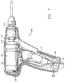
- FIG. 7 a second embodiment of the shielded wire-wrap tool is shown.
- This embodiment is powered by a standard AC power source, such as 120 V, 60 Hz current. It has been found that an AC powered wire-wrap tool generates much more EMI than the DC tool discussed above, both because of its higher voltage and its cyclic nature. For this reason, it is more difficult to achieve adequate damping of the EMI in the electric tool. Therefore, several additional damping components have been found to be necessary to provision of an acceptably shielded electric tool.
- the preferred electric wire-wrap tool 100 includes a trigger switch 110, a zero-voltage cross-over switch 120, and a motor assembly 140.
- the clutch, drive, and bit assemblies 112, 114, 116 of the electric tool are substantially the same as those of the battery-powered tool.
- Power is preferably transmitted to the electric tool via a three-wire cord set 102, which includes two conductors 104, 106 and a ground wire 108.
- cord set 102 includes conventional cord shielding means (not shown), to reduce EMI emitted by the conductors.
- Conductor 106 connects directly to the power input of zero-voltage cross-over switch 120.
- trigger switch 110 includes a pair of contacts 113, 115.
- Conductor 104 connects to contact 113 and also to one terminal of motor assembly 140, while contact 115 connects to the control input of zero-voltage cross-over switch 120.
- the output of zero-voltage cross-over switch 120 connects to the second terminal of motor assembly 140.
- a high-value resistor 116 and a low value capacitor 118 are connected in series across contacts 113, 115, in order to damp out start-up spikes. In assembly of the tool, it has been found preferable to attach resistor 116 and capacitor 118 as closely as possible to the circuit board, as longer lead wires to these components tend to act as mini-antennae and emit more EMI.
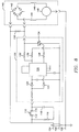
- Zero-voltage cross-over switch 120 may be constructed by any conventional means. According to the preferred embodiment shown in Figure 8, zero-voltage cross-over switch 120 includes a pair of diodes 122, 124, a zero-voltage cross-over chip 126, at least three resistors 128,130 and 132, and a bidirectional triode thyristor (triac) 134. As will be understood, zero-voltage cross-over chip 126 controls triac 134, triggering it at the beginning of each reversal of current in the alternating current cycle. Because triac 134 is connected between conductor 106 of the power supply and the second terminal of motor assembly 140, triggering of triac 134 results in the flow of current to motor assembly 140. Inclusion of zero-voltage cross-over switch 120 in the circuit reduces both the turn-on and turn-off spikes and reduces the EMI and RFI emitted by the tool.
- triac triode thyristor
- motor assembly 140 includes a full wave bridge rectifier 142, a pair of chokes 144, 146, and a DC motor 148.
- DC motor is preferably completely enclosed by a metal case, which serves as a shield to prevent emission of EMI and RFI from the motor.
- a DC motor is preferred over an AC motor in this application, as DC motors are smaller, achieve maximum rpm sooner, and have a higher start-up torque than AC motors in general.
- the power is converted to DC in rectifier 142. While it is not necessary to house rectifier 142 and chokes 144, 146 within the metal casing of motor assembly 140, it has been found that enclosing them therein helps to reduce emitted EMI.
- resistor 150 across the terminals of motor assembly 140, to increase the load on triac 134, to improve the turn-on characteristics, as otherwise the motor load would be too light for triac 134.
- Other components may be substituted for those described above, as will be understood by one skilled in the art.
- Casing 160 is preferably a conventional, plastic casing, the inside of which has been coated with a metallic shielding composition.
- the shielding composition comprises an acrylic-based, silver/copper composition suitable for spray application.
- An example of the preferred compound is Electrodag® 438, manufactured by Acheson Colloids Company of Port Huron, Michigan.
- Other compounds, such as those containing silver, nickel, graphite and combinations thereof are equally effective, but are made less suitable by cost, environmental concerns and the like.
Landscapes
- Engineering & Computer Science (AREA)
- Manufacturing & Machinery (AREA)
- Control Of Ac Motors In General (AREA)
Applications Claiming Priority (2)
| Application Number | Priority Date | Filing Date | Title |
|---|---|---|---|
| US08/169,511 US5458159A (en) | 1993-12-17 | 1993-12-17 | Shielded electrically powered wire wrap tool |
| US169511 | 1998-10-08 |
Publications (2)
| Publication Number | Publication Date |
|---|---|
| EP0658962A2 true EP0658962A2 (de) | 1995-06-21 |
| EP0658962A3 EP0658962A3 (de) | 1995-10-25 |
Family
ID=22616002
Family Applications (1)
| Application Number | Title | Priority Date | Filing Date |
|---|---|---|---|
| EP94308984A Ceased EP0658962A3 (de) | 1993-12-17 | 1994-12-02 | Abgeschirmtes elektrisch betriebenes Wickelwerkzeug. |
Country Status (2)
| Country | Link |
|---|---|
| US (1) | US5458159A (de) |
| EP (1) | EP0658962A3 (de) |
Cited By (1)
| Publication number | Priority date | Publication date | Assignee | Title |
|---|---|---|---|---|
| US6034711A (en) * | 1996-03-06 | 2000-03-07 | Hewlett-Packard Company | Self-indicating test page for use in setting density level and color balance in a color laser printer |
Families Citing this family (12)
| Publication number | Priority date | Publication date | Assignee | Title |
|---|---|---|---|---|
| US5657417A (en) * | 1995-05-02 | 1997-08-12 | Burndy Corporation | Control for battery powered tool |
| USD436510S1 (en) | 2000-01-18 | 2001-01-23 | Ok International Inc. | Wire-wrap/unwrap hand tool |
| US6927524B2 (en) * | 2001-11-27 | 2005-08-09 | Wavecrest Laboratories, Llc | Rotary electric motor having separate control modules for respective stator electromagnets |
| US20060137178A1 (en) * | 2004-12-23 | 2006-06-29 | Kevin Larkin | Wire wrapper |
| US7414337B2 (en) * | 2005-03-14 | 2008-08-19 | Black & Decker Inc. | Scrubber |
| US20070283559A1 (en) * | 2006-06-09 | 2007-12-13 | Albert Jackson | Wire twisting device |
| JP2010155291A (ja) * | 2008-12-26 | 2010-07-15 | Makita Corp | 電動工具 |
| US8373317B2 (en) * | 2009-05-04 | 2013-02-12 | Ingersoll Rand Company | RFI suppression system and method of mounting for DC cordless tools |
| US8136337B2 (en) * | 2009-12-23 | 2012-03-20 | Albert Jackson | Wire twisting device |
| DE102010003583A1 (de) * | 2010-04-01 | 2011-10-06 | Robert Bosch Gmbh | Handgeführtes Elektrowerkzeug |
| CN106972701A (zh) * | 2016-01-14 | 2017-07-21 | 德昌电机(深圳)有限公司 | 端盖装置及应用该端盖装置的电机 |
| DE102016220070A1 (de) * | 2016-10-14 | 2018-04-19 | Robert Bosch Gmbh | Entstörsystem, Antrieb und Handwerkzeugmaschine |
Family Cites Families (7)
| Publication number | Priority date | Publication date | Assignee | Title |
|---|---|---|---|---|
| US3699366A (en) * | 1971-06-07 | 1972-10-17 | Black & Decker Mfg Co | Power tool with motor support means |
| US4194700A (en) * | 1976-04-23 | 1980-03-25 | O.K. Machine And Tool Corporation | Battery-powered wire wrapping tool and wrapping bit |
| US4175247A (en) * | 1978-06-26 | 1979-11-20 | Cooper Industries, Inc. | Electric motor control for conductor wrapping tool |
| US4380111A (en) * | 1980-09-08 | 1983-04-19 | Cooper Industries, Inc. | Cutting, stripping and wrapping bit |
| DE3413233A1 (de) * | 1984-04-07 | 1985-11-14 | Robert Bosch Gmbh, 7000 Stuttgart | Handwerkzeugmaschine mit einem elektromotor |
| US4751452A (en) * | 1986-02-24 | 1988-06-14 | Cooper Industries | Battery operated power wrap tool |
| EP0408985A3 (en) * | 1989-07-15 | 1992-02-26 | Ceka Elektrowerkzeuge Ag + Co.Kg | Hand held electric tool |
-
1993
- 1993-12-17 US US08/169,511 patent/US5458159A/en not_active Expired - Lifetime
-
1994
- 1994-12-02 EP EP94308984A patent/EP0658962A3/de not_active Ceased
Cited By (1)
| Publication number | Priority date | Publication date | Assignee | Title |
|---|---|---|---|---|
| US6034711A (en) * | 1996-03-06 | 2000-03-07 | Hewlett-Packard Company | Self-indicating test page for use in setting density level and color balance in a color laser printer |
Also Published As
| Publication number | Publication date |
|---|---|
| EP0658962A3 (de) | 1995-10-25 |
| US5458159A (en) | 1995-10-17 |
Similar Documents
| Publication | Publication Date | Title |
|---|---|---|
| US5982253A (en) | In-line module for attenuating electrical noise with male and female blade terminals | |
| US5458159A (en) | Shielded electrically powered wire wrap tool | |
| US6078117A (en) | End cap assembly and electrical motor utilizing same | |
| US6177740B1 (en) | Integrated motor and motor drive unit | |
| US6400058B1 (en) | Universal motor with reduced EMI characteristics | |
| CN1037726C (zh) | 混合开关 | |
| US7259971B1 (en) | Encapsulated electronic power converter with embedded AC components | |
| CN101589536B (zh) | 电刷换向的电动马达 | |
| EP0855783B1 (de) | Anschlussvorrichtung für einen Anschlussdraht eines Elektromotors | |
| CN101061623B (zh) | 用于抑制直流电机的高频干扰发射的抗干扰装置 | |
| JP2006123034A (ja) | アース付携帯用電動工具 | |
| US20050285463A1 (en) | Brush assemblies | |
| GB1479545A (en) | Stator coil assemblies for rotary electric machines | |
| KR200243761Y1 (ko) | 직류모터의 전자파 필터 장착구조 | |
| EP0818099A1 (de) | Abschluss mit spannungsregler | |
| JPS5879452A (ja) | 電動機器 | |
| US4700157A (en) | Connector plug having a radio frequency suppression filter | |
| JP2000333396A (ja) | 電動機及びこの電動機の可変速駆動システム | |
| US20230052201A1 (en) | Dc excited brushed motor with a pluggable suppressor for the commutation system and sliding roof with such a motor | |
| JP2002118947A (ja) | 高電圧ケーブルの接続構造 | |
| US20040047105A1 (en) | Protecting device for electrical appliances | |
| JPS62208582A (ja) | 電源回路基板 | |
| GB2224402A (en) | Solid state station protector device | |
| JPH11266528A (ja) | 電子機器 | |
| JPH10261460A (ja) | チョークコイル内蔵コネクタ |
Legal Events
| Date | Code | Title | Description |
|---|---|---|---|
| PUAI | Public reference made under article 153(3) epc to a published international application that has entered the european phase |
Free format text: ORIGINAL CODE: 0009012 |
|
| AK | Designated contracting states |
Kind code of ref document: A2 Designated state(s): AT BE CH DE DK ES FR GB GR IE IT LI LU MC NL PT SE |
|
| RAX | Requested extension states of the european patent have changed |
Free format text: LT PAYMENT 941222;SI PAYMENT 941222 |
|
| PUAL | Search report despatched |
Free format text: ORIGINAL CODE: 0009013 |
|
| AK | Designated contracting states |
Kind code of ref document: A3 Designated state(s): AT BE CH DE DK ES FR GB GR IE IT LI LU MC NL PT SE |
|
| 17P | Request for examination filed |
Effective date: 19960412 |
|
| RAP1 | Party data changed (applicant data changed or rights of an application transferred) |
Owner name: COOPER INDUSTRIES, INC. |
|
| 17Q | First examination report despatched |
Effective date: 19981228 |
|
| GRAG | Despatch of communication of intention to grant |
Free format text: ORIGINAL CODE: EPIDOS AGRA |
|
| 17Q | First examination report despatched |
Effective date: 19981228 |
|
| STAA | Information on the status of an ep patent application or granted ep patent |
Free format text: STATUS: THE APPLICATION HAS BEEN REFUSED |
|
| 18R | Application refused |
Effective date: 20000814 |