EP0658971A1 - Système de contrôle d'alimentation d'un moteur asynchrone - Google Patents
Système de contrôle d'alimentation d'un moteur asynchrone Download PDFInfo
- Publication number
- EP0658971A1 EP0658971A1 EP19940402644 EP94402644A EP0658971A1 EP 0658971 A1 EP0658971 A1 EP 0658971A1 EP 19940402644 EP19940402644 EP 19940402644 EP 94402644 A EP94402644 A EP 94402644A EP 0658971 A1 EP0658971 A1 EP 0658971A1
- Authority
- EP
- European Patent Office
- Prior art keywords
- motor
- angle
- voltage
- speed
- axis
- Prior art date
- Legal status (The legal status is an assumption and is not a legal conclusion. Google has not performed a legal analysis and makes no representation as to the accuracy of the status listed.)
- Granted
Links
Images


Classifications
-
- H—ELECTRICITY
- H02—GENERATION; CONVERSION OR DISTRIBUTION OF ELECTRIC POWER
- H02P—CONTROL OR REGULATION OF ELECTRIC MOTORS, ELECTRIC GENERATORS OR DYNAMO-ELECTRIC CONVERTERS; CONTROLLING TRANSFORMERS, REACTORS OR CHOKE COILS
- H02P29/00—Arrangements for regulating or controlling electric motors, appropriate for both AC and DC motors
- H02P29/02—Providing protection against overload without automatic interruption of supply
- H02P29/032—Preventing damage to the motor, e.g. setting individual current limits for different drive conditions
-
- H—ELECTRICITY
- H02—GENERATION; CONVERSION OR DISTRIBUTION OF ELECTRIC POWER
- H02P—CONTROL OR REGULATION OF ELECTRIC MOTORS, ELECTRIC GENERATORS OR DYNAMO-ELECTRIC CONVERTERS; CONTROLLING TRANSFORMERS, REACTORS OR CHOKE COILS
- H02P21/00—Arrangements or methods for the control of electric machines by vector control, e.g. by control of field orientation
- H02P21/14—Estimation or adaptation of machine parameters, e.g. flux, current or voltage
- H02P21/18—Estimation of position or speed
-
- H—ELECTRICITY
- H02—GENERATION; CONVERSION OR DISTRIBUTION OF ELECTRIC POWER
- H02P—CONTROL OR REGULATION OF ELECTRIC MOTORS, ELECTRIC GENERATORS OR DYNAMO-ELECTRIC CONVERTERS; CONTROLLING TRANSFORMERS, REACTORS OR CHOKE COILS
- H02P21/00—Arrangements or methods for the control of electric machines by vector control, e.g. by control of field orientation
Definitions
- the present invention relates to a power control system for an asynchronous type motor.
- Asynchronous motors are generally supplied from an AC network via a variable speed drive.
- the variable speed drive is a frequency converter comprising a rectifier bridge connected to the network, an intermediate DC voltage circuit provided with a capacitor, and an inverter provided with static switches controlled by a pulse modulation device and connected to the windings. motor phase.
- the invention therefore aims to provide a system allowing, after the power supply to the motor, a resumption of speed control without occurrence of overcurrent.
- the electric speed ⁇ of the motor it is necessary to determine the electric speed ⁇ of the motor and to angularly position the voltage vector relative to the flux of the motor at the time of the reappearance of the power supply.
- the voltage vector is a mathematical representation translating the resultant of the actual voltages applied to the motor, and that the electric speed is the product of the mechanical speed of the motor by the number of poles.
- controlled speed recovery such as an identification structure, which on the one hand estimates the electric speed of the motor, and on the other hand, angularly positions the voltage vector in a rotating reference frame. orthogonal (d, q) where the axis (d) corresponds to the flow of the motor.
- the identification structure advantageously comprises a structure for estimating the speed produced from an angle calculation block which determines the angular position of the voltage vector by calculating its angle ⁇ relative to an orthogonal coordinate system ( ⁇ , ⁇ ) fixed relative to the stator of the motor, and of a diverter block which derives the angle ⁇ .
- the angle calculation block determines the coordinates V ⁇ and V ⁇ of the voltage vector in the fixed frame of reference ( ⁇ , ⁇ ) to deduce the angle ⁇ therefrom.
- a positioning block angularly positions the voltage vector in phase quadrature with respect to the estimated flux of the motor.
- the controlled recovery means also include a device for gradually increasing the component V q of the voltage which is increased to a control value according to a time constant as a function of the rotor time constant.
- the system may include a cascade regulation structure which makes it possible to limit the current when the evolution of the estimated voltage towards the motor control voltage is faster than the rotor time constant.
- the system is associated with a three-phase asynchronous type motor M.
- the initial electric speed of the motor ⁇ ref is supplied by a ramp generator.
- the ramp generator received as input a set speed ⁇ cons set by the user.
- the motor is supplied from an alternative network by means of a frequency converter type frequency converter.
- the static frequency converter 10 illustrated in FIG. 1 is connected to the three-phase or possibly single-phase alternating voltage network.
- the converter is of the voltage wave type and comprises a three-phase rectifier bridge 11, an intermediate DC voltage circuit 12 and an inverter 13.
- the rectifier bridge 11 has 6 diodes connected to the phases of the network so as to deliver a DC voltage to the intermediate circuit 12.
- the intermediate circuit comprises two respective high and low conductors 14, 15 between which a filtering capacitor 16 is disposed.
- the inverter 13 is connected, on the input side, to the conductors 14, 15 and, on the output side, to the phase conductors A, B, C of the asynchronous motor M.
- the inverter comprises three pairs of controlled static switches, T1-T6 in parallel with which respective recovery diodes D1, D6 are arranged.
- Each pair of switches comprises two cascaded switches T1, T4; T3, T6; T5, T2, one of which T1, T3, T5 is said to be high channel and the other T4, T6, T2 is said to be low channel.
- the midpoint of each pair is connected to a respective phase winding of the motor.
- a control circuit 20 makes it possible to turn the switches T1 to T6 on and off at the selected times.
- Current reading members 21 and 22 constituted by sensors of the current flowing in the different phases are provided on the phase conductors A and B. They deliver current signals IA and IB read in a fixed three-phase reference (A, B , C) corresponding to the windings of phases A, B and C so as to generate the missing current signal IC.
- a coordinate transformation block 23 transforms the current signals I A , I B and l C into a current signal Iq, component of the current in a rotating frame (d, q) and representing the torque of the motor.
- the reference (d, q) rotates at synchronous speed, the axis d corresponding to the flow of the motor, and the axis q being arranged at ⁇ 2 in front of axis d.
- Block 23 delivers the module
- the system also includes a structure 24 with cascade regulations.
- the structure includes a frequency regulator 25 and a current regulator 26.
- Each regulator normally consists of a PI amplifier.
- the frequency regulator 25 receives the frequency ⁇ ref from a ramp generator 25a and in feedback the return frequency ⁇ ret , estimated speed of the motor, delivered by the current regulator 26.
- the current regulator 26 receives a current reference voltage generated at the output of the frequency regulator, this current represents the current which should circulate in the motor, and in feedback the current signal delivered by the block 23. At output the current regulator controls the control circuit 20 of the inverter.
- the current reference voltage can be clipped by a limiter 27. The result is to protect the motor.
- the system comprises an identification structure 28 provided with voltage reading members 29, 30, 31, a coordinate transformation block 32, an angle calculation block 33, a derivative block 34 and a positioning block 35.
- the voltage reading members 29, 30 and 31 constituted by voltage sensors are provided on the phase conductors A, B and C. They deliver voltages V A , V B and V C read in the fixed reference (A, B, C) and components of the voltage vector.
- the coordinate transformation block 32 transforms the voltages V A , V B , V C into voltages V ⁇ and V ⁇ in a fixed two-phase frame ( ⁇ , ⁇ ).
- the reference ( ⁇ , ⁇ ), represented in FIG. 2, is defined by two perpendicular axes ( ⁇ , ⁇ ), ( ⁇ ) being the axis supporting the phase A winding of the motor and ( ⁇ ) being disposed at ⁇ 2 in front of the axis ( ⁇ ).
- the calculation block 33 makes it possible from the coordinates V ⁇ and V ⁇ of the voltage vector to know and to determine its angular position in the fixed frame of reference ( ⁇ , ⁇ ).
- We define the angle ⁇ made by the tension vector with the axis ( ⁇ ) in general by: ⁇ ATN ( V ⁇ V ⁇ ).
- the calculation block 33 includes a calculation element which determines the value x equal to V ⁇ V ⁇ and a table that defines the ATN (x) function. It delivers the angle ⁇ corresponding to the calculated value x.
- Step 101 shows that it is also necessary to take account of the sign of V ⁇ and V ⁇ .
- the voltage vector can be in any one of the quadrants of the reference ( ⁇ , ⁇ ), it is necessary to bring back the vector in the first quadrant so that the angle ⁇ is between 0 and ⁇ 4 .
- Step 102 corresponds to the calculation of the variation of angle ⁇ between two samplings.
- the variation must not exceed a certain value (for example ⁇ ); if it is the case it is necessary to subtract ⁇ 2 ⁇ according to the sign of this variation to remove any discontinuity from 0 to 2 ⁇ .
- angle ⁇ is coded by a number of 16 bits for example such that 216 represents 2 ⁇
- the operations ⁇ 2 ⁇ which have just been mentioned are not necessary. They are shown in gray on the algorithm.
- Step 103 shows the calculation of the electric motor speed as a function of the angle variation calculated in step 102 and the time elapsed between two samplings.
- the component on the axis q of the voltage vector is named V q .
- the resumption on the fly is carried out after a network interruption. This cut is long enough and you cannot keep control of the engine. Consequently, the engine is coasted.
- Block 32 transforms the coordinates V A , V B and V C into V ⁇ and V ⁇ in the coordinate system ( ⁇ , ⁇ ).
- the block 33 calculates the angle ⁇ and the diverter block 34 delivers the electric speed of the motor which is sent to the ramp generator 25a to reset the reference speed ⁇ ref .
- the block 35 positions the tension vector in the reference (d, q) so that it is carried by the axis q.
- the reapplied voltage is equal in module and in phase to the voltage developed by the motor.
- the controlled recovery means 28 also include a device 36 for gradually increasing the component V q of the voltage which is increased to a control value according to a time constant as a function of the rotor time constant.
Landscapes
- Engineering & Computer Science (AREA)
- Power Engineering (AREA)
- Control Of Ac Motors In General (AREA)
Abstract
Description
- La présente invention concerne un système de contrôle d'alimentation d'un moteur de type asynchrone.
- Les moteurs asynchrones sont généralement alimentés à partir d'un réseau alternatif par l'intermédiaire d'un variateur de vitesse. Le variateur de vitesse est un convertisseur de fréquence comprenant un pont redresseur relié au réseau, un circuit intermédiaire de tension continue muni d'un condensateur, et un onduleur doté d'interrupteurs statiques commandés par un dispositif à modulation d'impulsions et relié aux enroulements de phase du moteur.
- Il est connu, lors d'une coupure d'alimentation du moteur, de laisser tourner celui-ci en roue libre. On garde ainsi le contrôle du dispositif de commande.
- Cependant la reprise à la volée du contrôle de la vitesse initiale du moteur effectuée sans précaution peut entraîner des surintensités importantes ainsi qu'une perte momentanée de la vitesse. Les pics d'intensités risquent d'endommager les interrupteurs disposés dans l'onduleur.
- L'invention a par conséquent pour but de réaliser un système permettant, après la coupure d'alimentation du moteur, une reprise de contrôle de la vitesse sans apparition de surintensité.
- Ainsi il convient de déterminer la vitesse électrique ω du moteur et de positionner angulairement le vecteur tension par rapport au flux du moteur au moment de la réapparition de l'alimentation. On rappelle que le vecteur tension est une représentation mathématique traduisant la résultante des tensions réelles appliquées au moteur, et que la vitesse électrique est le produit de la vitesse mécanique du moteur par le nombre de pôles.
- Ce but est atteint grâce à des moyens de reprise contrôlée de la vitesse tels qu'une structure d'identification, qui d'une part estime la vitesse électrique du moteur, et d'autre part, positionne angulairement le vecteur tension dans un repère tournant orthogonal (d,q) où l'axe (d) correspond au flux du moteur.
- La structure d'identification comprend avantageusement une structure d'estimation de la vitesse réalisée à partir d'un bloc de calcul d'angle qui détermine la position angulaire du vecteur tension en calculant son angle α par rapport à un repère orthogonal (α,β) fixe par rapport au stator du moteur, et d'un bloc dérivateur qui dérive l'angle α.
- Le bloc de calcul d'angle détermine les coordonnées Vα et Vβ du vecteur tension dans le repère fixe (α,β) pour en déduire l'angle α.
- Un bloc de positionnement positionne angulairement le vecteur tension en quadrature de phase par rapport au flux estimé du moteur.
- Les moyens de reprise contrôlée comportent aussi un dispositif d'augmentation progressive de la composante Vq de la tension qui est augmentée jusqu'à une valeur de commande suivant une constante de temps fonction de la constante de temps rotorique.
- Par ailleurs, le système peut comprendre une structure à régulations en cascade qui permet de limiter le courant lorsque l'évolution de la tension estimée vers la tension de commande du moteur est plus rapide que la constante de temps rotorique.
- La description faite ci-après en regard des dessins fera ressortir les caractéristiques et avantages de l'invention suivant un mode de réalisation particulier.
- la figure 1 représente le schéma du système conforme à l'invention ;
- la figure 2 représente un vecteur tension dans un repère fixe (α,β);
- la figure 3 représente l'algorithme correspondant à l'estimation de la vitesse électrique ω du moteur en fonction de la position angulaire du vecteur tension dans le repère (α,β);
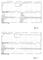
- la figure 4 simule une reprise à la volée non contrôlée ;
- la figure 5 simule une reprise à la volée contrôlée ;
- Le système est associé à un moteur M de type asynchrone triphasé.
- La vitesse électrique initiale du moteur ωref est fournie par un générateur de rampe. Le générateur de rampe a reçu en entrée une vitesse de consigne ωcons fixée par l'utilisateur.
- Le moteur est alimenté à partir d'un réseau altematif par l'intermédiaire d'un variateur de vitesse de type convertisseur de fréquence.
- Le convertisseur statique de fréquence 10 illustré sur la figure 1 est relié au réseau de tension alternative triphasé ou éventuellement monophasé. Le convertisseur est du type à onde de tension et comporte un pont redresseur triphasé 11, un circuit intermédiaire de tension continue 12 et un onduleur 13.
- Le pont redresseur 11 présente 6 diodes connectées aux phases du réseau de manière à délivrer en sortie une tension continue au circuit intermédiaire 12.
- Le circuit intermédiaire comprend deux conducteurs 14,15 respectifs de voie haute et de voie basse entre lesquels est disposé un condensateur 16 de filtrage.
- L'onduleur 13 est relié, côté entrée, aux conducteurs 14,15 et, côté sortie, aux conducteurs de phase A, B, C du moteur asynchrone M.
- L'onduleur comprend trois couples d'interrupteurs statiques commandés, T1-T6 en parallèle auxquels sont disposées des diodes respectives D1,D6 de récupération. Chaque couple d'interrupteurs comporte deux interrupteurs cascadés T1,T4 ; T3,T6 ; T5,T2 dont l'un T1,T3,T5 est dit de voie haute et l'autre T4,T6,T2 dit de voie basse. Le point milieu de chaque couple est connecté à un enroulement de phase respectif du moteur. Un circuit de commande 20 permet de rendre passants et bloquants les interrupteurs T1 à T6 aux instants choisis.
- Des organes de lecture de courant 21 et 22 constitués par des capteurs du courant circulant dans les différentes phases sont prévus sur les conducteurs de phase A et B. Ils délivrent des signaux de courant IA et IB lus dans un repère triphasé fixe (A,B,C) correspondant aux enroulements de phases A, B et C de manière à engendrer le signal de courant manquant IC.
- Un bloc 23 de transformation de coordonnées transforme les signaux de courant IA, IB et lC en un signal de courant Iq, composante du courant dans un repère tournant (d,q) et représentant le couple du moteur. Le repère (d, q) tourne à la vitesse de synchronisme, l'axe d correspondant au flux du moteur, et l'axe q étant disposé à

- Le système comporte aussi une structure 24 à régulations en cascade. La structure comprend un régulateur de fréquence 25 et un régulateur de courant 26 .
- Chaque régulateur est normalement constitué d'un amplificateur PI.
- Le régulateur de fréquence 25 reçoit la fréquence ωref issue d'un générateur de rampe 25a et en contre-réaction la fréquence de retour ωret, vitesse estimée du moteur, délivrée par le régulateur de courant 26.
- Le régulateur de courant 26 reçoit une tension de référence de courant engendrée en sortie du régulateur de fréquence, ce courant représente le courant qui devrait circuler dans le moteur, et en contre-réaction le signal de courant délivré par le bloc 23. En sortie le régulateur de courant pilote le circuit de commande 20 de l'onduleur.
- La tension de référence de courant peut être écrêtée par un limiteur 27. Le résultat consiste à protéger le moteur.
- Enfin le système comporte une structure d'identification 28 dotée d'organes de lecture de tension 29, 30, 31, d'un bloc de transformation de coordonnées 32, d'un bloc de calcul d'angle 33, d'un bloc dérivateur 34 et d'un bloc de positionnement 35.
- Les organes de lecture de tension 29, 30 et 31 constitués par des capteurs de tension sont prévus sur les conducteurs de phase A, B et C. Ils délivrent des tensions VA, VB et VC lues dans le repère fixe (A,B,C) et composantes du vecteur tension.
- Le bloc 32 de transformation de coordonnées transforme les tensions VA, VB, VC en des tensions Vα et Vβ dans un repère diphasé fixe (α, β). Le repère (α, β), représenté à la figure 2, se définit par deux axes perpendiculaires (α, β), (α) étant l'axe supportant l'enroulement de phase A du moteur et (β) étant disposé à

- Le bloc de calcul 33 permet à partir des coordonnées Vα et Vβ du vecteur tension de connaître et de déterminer sa position angulaire dans le repère fixe (α, β). On définit l'angle α que fait le vecteur tension avec l'axe (α) de façon générale par :

- Le bloc de calcul 33 comprend un élément de calcul qui détermine la valeur x égale à

- Enfin le bloc dérivateur 34 permet d'estimer la vitesse électrique ω du moteur telle que ω =

- Les différentes étapes réalisées par les blocs 33 et 34 sont illustrées plus en détail à la figure 3.
- L'étape 100 consiste à définir l'équation de l'angle a suivant la valeur du module de x. La fonction ATN (x) est définie par une table de valeurs pour x variant seulement de 0 à 1, par conséquent :
- si le module de x est inférieur à 1, on utilise la relation α = ATN (|

- si le module de x est supérieur à 1, on utilise la relation α =


- L'étape 101 montre qu'il est aussi nécessaire de tenir compte du signe de Vα et Vβ. En effet le vecteur tension pouvant être dans l'un quelconque des quadrants du repère (α, β), il faut ramener le vecteur dans le premier quadrant afin que l'angle α soit compris entre 0 et

- Ainsi, l'angle α calculé à l'étape 100 pourra être corrigé :
- si

- si

- si

- si
- L'étape 102 correspond au calcul de la variation d'angle α entre deux échantillonnages. La variation ne doit pas dépasser une certaine valeur (par exemple π) ; si c'est le cas il faut retrancher ± 2π suivant le signe de cette variation pour supprimer toute discontinuité de 0 à 2π.
- Si l'angle α est codé par un nombre de 16 bits par exemple tel que 2¹⁶ représente 2π, les opérations ± 2π qui viennent d'être mentionnées ne sont pas nécessaires. Elles sont représentées en grisé sur l'algorithme.
- L'étape 103 montre le calcul de la vitesse électrique du moteur en fonction de la variation d'angle calculée à l'étape 102 et le temps écoulé entre deux échantillonnages.
- Enfin le bloc de positionnement 35 permet en connaissant l'angle a de positionner le vecteur tension dans le repère (d,q) de façon qu'il soit porté par l'axe (q) en initialisant l'axe (d) correspondant au flux du moteur par rapport à l'axe (α) selon un angle ϑ, tel que ϑ = α -


- Le fonctionnement du dispositif va maintenant être décrit :
- Dans le mode de réalisation décrit, la reprise à la volée est effectuée après une coupure du réseau. Cette coupure est suffisamment longue et on ne peut pas garder le contrôle du moteur. Par conséquent le moteur est mis en roue libre.
- Lors de la reprise de réseau, si le dispositif de l'invention n'a pas été mis en oeuvre, on observe (figure 4) dès l'augmentation de la vitesse des pics importants d'intensité. En revanche, si le dispositif a été mis en oeuvre, aucune surintensité n'est observée (figure 5).
- Lors de la reprise du réseau, il s'agit alors de connaître la vitesse électrique ω du moteur. Ainsi, dès la coupure, on estime cette vitesse toutes les 255 µs par exemple.
- Les capteurs de tension délivrent la tension de chaque phase A, B et C du moteur. Le bloc 32 transforme les coordonnées VA,VB et VC en Vα et Vβ dans le repère (α,β).
- Le bloc 33 calcule l'angle α et le bloc dérivateur 34 délivre la vitesse électrique du moteur qui est envoyée au générateur de rampe 25a pour réinitialiser la vitesse de référence ωref.
- Le bloc 35 positionne dans le repère (d,q) le vecteur tension de façon qu'il soit porté par l'axe q.
- Ainsi lors de la reprise du réseau, pour éviter toute surintensité, la tension réappliquée est égale en module et en phase à la tension développée par le moteur.
- Les moyens de reprise contrôlée 28 comportent aussi un dispositif 36 d'augmentation progressive de la composante Vq de la tension qui est augmentée jusqu'à une valeur de commande suivant une constante de temps fonction de la constante de temps rotorique.
- Si cette évolution est plus lente que la constante de temps rotorique, il n'y aura pas de surintensité.
- Dans le cas contraire le courant sera limité par la structure 24 à régulations en cascade.
- Il est bien entendu que l'on peut sans sortir du cadre de l'invention, utiliser des variantes et des perfectionnements de détails.
Claims (6)
- Système de contrôle d'alimentation d'un moteur asynchrone alimenté par un réseau altematif par l'intermédiaire d'un variateur de vitesse (10) comportant un pont redresseur (11) relié au réseau, un circuit intermédiaire (12) de tension continue muni d'un condensateur (16) et un onduleur (13) muni d'interrupteurs et reliés aux enroulements de phase du moteur ; le système comportant des moyens de reprise contrôlée de la vitesse du moteur après une coupure d'alimentation du moteur, caractérisé en ce que les moyens de reprise contrôlée consistent en une structure (28) d'identification permettant d'estimer la vitesse électrique ω du moteur et de positionner angulairement le vecteur tension dans un repère tournant orthogonal (d,q) où l'axe (d) correspond au flux du moteur et l'axe (q) étant disposé à

- Système selon la revendication 1, caractérisé en ce que la structure d'identification (28) comporte une structure d'estimation de la vitesse ω réalisée à partir d'un bloc de calcul d'angle (33) qui détermine la position angulaire du vecteur tension en calculant son angle α par rapport à un repère orthogonal (α,β) fixe par rapport au stator du moteur, et d'un bloc dérivateur (34) qui dérive l'angle α.
- Système selon la revendication 2, caractérisé en ce que le bloc de calcul d'angle (33) détermine l'angle α par le calcul de


- Système selon l'une quelconque des revendications, caractérisé en ce que la structure d'identification (28) comprend un bloc de positionnement (35) du vecteur tension dans le repère (d,q) de façon que le vecteur tension soit porté par l'axe (q) en initialisant l'axe (d) par rapport à l'axe (α) selon un angle ϑ, tel que ϑ = α -


- Système selon l'une quelconque des revendications, caractérisé en ce que les moyens de reprise contrôlée comportent un dispositif d'augmentation progressive de la composante Vq de la tension dans le repère (d, q) qui est augmentée jusqu'à une valeur de commande suivant une constante de temps fonction de la constante de temps rotorique.
- Système selon l'une quelconque des revendications précédentes, caractérisé en ce qu'il comporte une structure (24) à régulations en cascade et que cette structure permet de limiter le courant lorsque l'évolution de la tension estimée vers la tension de commande du moteur est plus rapide que la constante de temps rotorique.
Applications Claiming Priority (2)
| Application Number | Priority Date | Filing Date | Title |
|---|---|---|---|
| FR9315274 | 1993-12-16 | ||
| FR9315274A FR2714234B1 (fr) | 1993-12-16 | 1993-12-16 | Système de contrôle d'alimentation d'un moteur asynchrone. |
Publications (2)
| Publication Number | Publication Date |
|---|---|
| EP0658971A1 true EP0658971A1 (fr) | 1995-06-21 |
| EP0658971B1 EP0658971B1 (fr) | 1998-07-22 |
Family
ID=9454097
Family Applications (1)
| Application Number | Title | Priority Date | Filing Date |
|---|---|---|---|
| EP19940402644 Expired - Lifetime EP0658971B1 (fr) | 1993-12-16 | 1994-11-21 | Système de contrÔle d'alimentation d'un moteur asynchrone |
Country Status (4)
| Country | Link |
|---|---|
| US (1) | US5644205A (fr) |
| EP (1) | EP0658971B1 (fr) |
| DE (1) | DE69411866T2 (fr) |
| FR (1) | FR2714234B1 (fr) |
Families Citing this family (16)
| Publication number | Priority date | Publication date | Assignee | Title |
|---|---|---|---|---|
| FR2746982B1 (fr) * | 1996-03-28 | 1998-05-07 | Schneider Electric Sa | Convertisseur de frequence pour moteur alternatif |
| AUPP208798A0 (en) | 1998-03-02 | 1998-03-26 | Casttikulm Research Pty Ltd | Motor controller |
| DE29809768U1 (de) * | 1998-05-20 | 1999-09-23 | Elektra Beckum Ag, 49716 Meppen | Tragbare Werkzeugmaschine, insbesondere Tischkreissäge |
| US5905644A (en) * | 1998-07-31 | 1999-05-18 | Allen-Bradley Company, Llc | DC bus voltage controller |
| DE19843133C2 (de) * | 1998-09-21 | 2001-03-15 | Siemens Ag | Verfahren zum Messen der Drehzahl einer Induktionsmaschine und zugehörige Einrichtung |
| CA2401167A1 (fr) | 2001-09-05 | 2003-03-05 | Her Majesty The Queen In Right Of Canada As Represented By The Minister Of National Defence | Methode d'estimation de la vitesse d'un moteur pour maintenir sa stabilite |
| US6876944B2 (en) * | 2002-09-04 | 2005-04-05 | Her Majesty The Queen In Right Of Canada, As Represented By The Minister Of National Defence | Motor speed estimation for stabilized motor control |
| US6809496B2 (en) * | 2002-09-16 | 2004-10-26 | Honeywell International Inc. | Position sensor emulator for a synchronous motor/generator |
| US20040221959A1 (en) * | 2003-05-09 | 2004-11-11 | Applied Materials, Inc. | Anodized substrate support |
| US7242175B2 (en) * | 2003-08-08 | 2007-07-10 | Stmicroelectronics, Inc. | Determining rotation of a freewheeling motor |
| US7782009B2 (en) * | 2004-08-24 | 2010-08-24 | Rockwell Automation Technologies, Inc. | Adjustable speed drive protection |
| DE102006052042A1 (de) * | 2006-10-30 | 2008-05-15 | Bombardier Transportation Gmbh | Steuerung und/oder Regelung eines 3-Phasen-Stromrichters für den Betrieb einer Asynchronmaschine |
| FR3024304B1 (fr) * | 2014-07-25 | 2018-03-02 | Somfy Sas | Procede et unite de controle et/ou de protection d’un actionneur d’un equipement mobile d’un batiment |
| CN104320032B (zh) * | 2014-09-30 | 2017-03-29 | 海信科龙电器股份有限公司 | 一种交‑交变频空调控制方法及控制器 |
| RU2660460C1 (ru) * | 2017-06-16 | 2018-07-06 | федеральное государственное автономное образовательное учреждение высшего образования "Южно-Уральский государственный университет (национальный исследовательский университет)" | Устройство частотного управления асинхронным электроприводом |
| US11196371B2 (en) * | 2020-01-10 | 2021-12-07 | DRiV Automotive Inc. | Sensorless position detection for electric motor |
Citations (5)
| Publication number | Priority date | Publication date | Assignee | Title |
|---|---|---|---|---|
| JPS57129198A (en) * | 1981-01-30 | 1982-08-11 | Hitachi Ltd | Controlling method and device for ac motor |
| JPS58130795A (ja) * | 1982-01-27 | 1983-08-04 | Hitachi Ltd | 交流電動機駆動用電源装置 |
| JPS5941194A (ja) * | 1982-08-30 | 1984-03-07 | Fuji Electric Co Ltd | 交流電動機の乱調防止方式 |
| EP0165020A2 (fr) * | 1984-06-11 | 1985-12-18 | Kabushiki Kaisha Toshiba | Convertisseur de puissance pour une charge à courant alternatif |
| EP0177114A1 (fr) * | 1984-09-05 | 1986-04-09 | Kabushiki Kaisha Meidensha | Procédé et système pour remettre en circuit un convertisseur pour les moteurs en rotation |
Family Cites Families (9)
| Publication number | Priority date | Publication date | Assignee | Title |
|---|---|---|---|---|
| JPH07108119B2 (ja) * | 1987-08-08 | 1995-11-15 | 三菱電機株式会社 | 誘導電動機制御装置 |
| US5285145A (en) * | 1988-08-30 | 1994-02-08 | Fuji Electric Co., Ltd. | Current-limit system for voltage-type inverter |
| US5184057A (en) * | 1989-09-14 | 1993-02-02 | Hitachi, Ltd. | Control method and device for ac motor |
| US5272429A (en) * | 1990-10-01 | 1993-12-21 | Wisconsin Alumni Research Foundation | Air gap flux measurement using stator third harmonic voltage and uses |
| JP2954333B2 (ja) * | 1990-11-28 | 1999-09-27 | 株式会社日立製作所 | 交流電動機可変速システム |
| DE69109832T2 (de) * | 1990-12-11 | 1995-10-05 | Meidensha Electric Mfg Co Ltd | Vektorsteuerung. |
| EP0571076B1 (fr) * | 1992-04-10 | 1996-01-17 | Matsushita Electric Industrial Co., Ltd. | Moteur à courant continu sans balai |
| JP3257566B2 (ja) * | 1992-06-16 | 2002-02-18 | 株式会社安川電機 | 誘導電動機のpgレスベクトル制御装置 |
| US5426357A (en) * | 1993-05-25 | 1995-06-20 | Satou; Nobuyasu | Control device for induction motor |
-
1993
- 1993-12-16 FR FR9315274A patent/FR2714234B1/fr not_active Expired - Fee Related
-
1994
- 1994-11-21 EP EP19940402644 patent/EP0658971B1/fr not_active Expired - Lifetime
- 1994-11-21 DE DE69411866T patent/DE69411866T2/de not_active Expired - Fee Related
- 1994-12-16 US US08/357,755 patent/US5644205A/en not_active Expired - Fee Related
Patent Citations (5)
| Publication number | Priority date | Publication date | Assignee | Title |
|---|---|---|---|---|
| JPS57129198A (en) * | 1981-01-30 | 1982-08-11 | Hitachi Ltd | Controlling method and device for ac motor |
| JPS58130795A (ja) * | 1982-01-27 | 1983-08-04 | Hitachi Ltd | 交流電動機駆動用電源装置 |
| JPS5941194A (ja) * | 1982-08-30 | 1984-03-07 | Fuji Electric Co Ltd | 交流電動機の乱調防止方式 |
| EP0165020A2 (fr) * | 1984-06-11 | 1985-12-18 | Kabushiki Kaisha Toshiba | Convertisseur de puissance pour une charge à courant alternatif |
| EP0177114A1 (fr) * | 1984-09-05 | 1986-04-09 | Kabushiki Kaisha Meidensha | Procédé et système pour remettre en circuit un convertisseur pour les moteurs en rotation |
Non-Patent Citations (5)
| Title |
|---|
| MASATO KOYAMA ET AL.: "Microprocessor-Based Vector Control System for Induction Motor Drives with Rotor Time Constant Identification Function", IEEE TRANSACTIONS ON INDUSTRY APPLICATIONS, vol. IA-22, no. 3, June 1986 (1986-06-01), NEW YORK US, pages 453 - 459 * |
| PATENT ABSTRACTS OF JAPAN vol. 6, no. 226 (E - 141) 11 November 1982 (1982-11-11) * |
| PATENT ABSTRACTS OF JAPAN vol. 7, no. 243 (E - 207) 28 October 1983 (1983-10-28) * |
| PATENT ABSTRACTS OF JAPAN vol. 8, no. 131 (E - 251)<1568> 19 June 1984 (1984-06-19) * |
| T.OURTH: "Commande vectorielle d'un moteur asynchrone sans capteur", JOURNAL DE PHYSIQUE, vol. 3, no. 6, June 1993 (1993-06-01), PARIS FR, pages 1123 - 1133, XP000368484 * |
Also Published As
| Publication number | Publication date |
|---|---|
| DE69411866D1 (de) | 1998-08-27 |
| FR2714234B1 (fr) | 1996-08-23 |
| US5644205A (en) | 1997-07-01 |
| DE69411866T2 (de) | 1998-12-03 |
| FR2714234A1 (fr) | 1995-06-23 |
| EP0658971B1 (fr) | 1998-07-22 |
Similar Documents
| Publication | Publication Date | Title |
|---|---|---|
| EP0658971B1 (fr) | Système de contrÔle d'alimentation d'un moteur asynchrone | |
| EP0925641B1 (fr) | Dispositif de detection de la position angulaire pour le pilotage d'un moteur synchrone a excitation par aimant permanent | |
| EP0579948B1 (fr) | Dispositif de commande d'un moteur asynchrone | |
| FR2532490A1 (fr) | Dispositif de commande d'un moteur a courant continu sans balais | |
| EP1881594A1 (fr) | Procédé d'ajustement de paramètres d'un moteur synchrone et variateur de vitesse utilisant un tel procédé | |
| EP0741448A1 (fr) | Procédé de commande d'un gradateur et dispositif pour la mise en oeuvre de ce procédé | |
| FR2486328A1 (fr) | Dispositif perfectionne d'economie d'energie pour moteurs a induction | |
| FR2990087A1 (fr) | Commande pour un circuit onduleur, onduleur et procede pour faire fonctionner un onduleur | |
| EP0658972B1 (fr) | Système de controle d'alimentation d'un moteur asynchrone | |
| FR2893786A1 (fr) | Procede et appareil de commande pour limiter le courant d'un systeme de pilotage d'une machine a induction | |
| EP0407253B1 (fr) | Dispositif de mesure dynamique du couple d'un moteur autosynchrone et dispositif de commande asservie d'un moteur autosynchrone utilisant ce dispositif | |
| FR2660126A1 (fr) | Procede de commande d'un moteur synchrone autopilote et dispositif pour sa mise en óoeuvre. | |
| EP0766886B1 (fr) | Procede de commande d'un gradateur de tension pour l'alimentation d'un moteur a induction | |
| FR2855679A1 (fr) | Procede et systeme de regulation du couple electromagnetique instantane, et support d'enregistrement pour la mise en oeuvre du procede | |
| EP1686682B1 (fr) | Procédé et système de limitation du courant en sortie d'un variateur de vitesse fonctionnant selon une loi de commande U/F. | |
| EP1837987A1 (fr) | Procédé d'identification des paramètres d'un câble moteur | |
| FR2675646A1 (fr) | Dispositif d'alimentation electrique comportant un circuit de commutation. | |
| FR2575006A1 (fr) | Procede et circuit electrique de commande pour assurer un branchement correct d'une alimentation triphasee a un dispositif electrique | |
| EP0241326A1 (fr) | Procédé de commande d'un onduleur à modulation de largeur par impulsions, associé à un moteur à N phases et dispositif de mise en oeuvre du procédé | |
| FR3143237A1 (fr) | Procédé de commande d’une machine électrique pilotée par un onduleur pourvu d’une pluralité de bras de commutation | |
| EP3121365B1 (fr) | Procédé de détection du sens de déplacement d'un écran d'occultation | |
| EP0788220A1 (fr) | Onduleur d'alimentation d'un moteur électrique de traction d'un véhicule | |
| EP3387743A1 (fr) | Procédé de compensation des effets non-linéaires d'un onduleur de tension | |
| FR3142631A1 (fr) | Procédé de commande d’une machine électrique pilotée par un onduleur commandé par un calculateur | |
| WO2021198594A2 (fr) | Procédé de commande d'un redresseur connecté à une génératrice électrique synchrone à aimants permanents pour fournir une tension continue, programme d'ordinateur et dispositif correspondant |
Legal Events
| Date | Code | Title | Description |
|---|---|---|---|
| PUAI | Public reference made under article 153(3) epc to a published international application that has entered the european phase |
Free format text: ORIGINAL CODE: 0009012 |
|
| 17P | Request for examination filed |
Effective date: 19941124 |
|
| AK | Designated contracting states |
Kind code of ref document: A1 Designated state(s): CH DE FR GB IT LI SE |
|
| 17Q | First examination report despatched |
Effective date: 19970124 |
|
| GRAG | Despatch of communication of intention to grant |
Free format text: ORIGINAL CODE: EPIDOS AGRA |
|
| GRAG | Despatch of communication of intention to grant |
Free format text: ORIGINAL CODE: EPIDOS AGRA |
|
| GRAG | Despatch of communication of intention to grant |
Free format text: ORIGINAL CODE: EPIDOS AGRA |
|
| GRAH | Despatch of communication of intention to grant a patent |
Free format text: ORIGINAL CODE: EPIDOS IGRA |
|
| GRAH | Despatch of communication of intention to grant a patent |
Free format text: ORIGINAL CODE: EPIDOS IGRA |
|
| GRAA | (expected) grant |
Free format text: ORIGINAL CODE: 0009210 |
|
| AK | Designated contracting states |
Kind code of ref document: B1 Designated state(s): CH DE FR GB IT LI SE |
|
| REG | Reference to a national code |
Ref country code: CH Ref legal event code: EP |
|
| REF | Corresponds to: |
Ref document number: 69411866 Country of ref document: DE Date of ref document: 19980827 |
|
| ITF | It: translation for a ep patent filed | ||
| GBT | Gb: translation of ep patent filed (gb section 77(6)(a)/1977) |
Effective date: 19980817 |
|
| PLBE | No opposition filed within time limit |
Free format text: ORIGINAL CODE: 0009261 |
|
| STAA | Information on the status of an ep patent application or granted ep patent |
Free format text: STATUS: NO OPPOSITION FILED WITHIN TIME LIMIT |
|
| 26N | No opposition filed | ||
| REG | Reference to a national code |
Ref country code: GB Ref legal event code: IF02 |
|
| PGFP | Annual fee paid to national office [announced via postgrant information from national office to epo] |
Ref country code: DE Payment date: 20071102 Year of fee payment: 14 |
|
| PGFP | Annual fee paid to national office [announced via postgrant information from national office to epo] |
Ref country code: IT Payment date: 20071115 Year of fee payment: 14 Ref country code: CH Payment date: 20071112 Year of fee payment: 14 |
|
| PGFP | Annual fee paid to national office [announced via postgrant information from national office to epo] |
Ref country code: SE Payment date: 20071018 Year of fee payment: 14 |
|
| PGFP | Annual fee paid to national office [announced via postgrant information from national office to epo] |
Ref country code: GB Payment date: 20071114 Year of fee payment: 14 Ref country code: FR Payment date: 20071109 Year of fee payment: 14 |
|
| REG | Reference to a national code |
Ref country code: CH Ref legal event code: PL |
|
| EUG | Se: european patent has lapsed | ||
| GBPC | Gb: european patent ceased through non-payment of renewal fee |
Effective date: 20081121 |
|
| PG25 | Lapsed in a contracting state [announced via postgrant information from national office to epo] |
Ref country code: IT Free format text: LAPSE BECAUSE OF NON-PAYMENT OF DUE FEES Effective date: 20081121 |
|
| REG | Reference to a national code |
Ref country code: FR Ref legal event code: ST Effective date: 20090731 |
|
| PG25 | Lapsed in a contracting state [announced via postgrant information from national office to epo] |
Ref country code: LI Free format text: LAPSE BECAUSE OF NON-PAYMENT OF DUE FEES Effective date: 20081130 Ref country code: DE Free format text: LAPSE BECAUSE OF NON-PAYMENT OF DUE FEES Effective date: 20090603 Ref country code: CH Free format text: LAPSE BECAUSE OF NON-PAYMENT OF DUE FEES Effective date: 20081130 |
|
| PG25 | Lapsed in a contracting state [announced via postgrant information from national office to epo] |
Ref country code: GB Free format text: LAPSE BECAUSE OF NON-PAYMENT OF DUE FEES Effective date: 20081121 |
|
| PG25 | Lapsed in a contracting state [announced via postgrant information from national office to epo] |
Ref country code: SE Free format text: LAPSE BECAUSE OF NON-PAYMENT OF DUE FEES Effective date: 20081122 |
|
| PG25 | Lapsed in a contracting state [announced via postgrant information from national office to epo] |
Ref country code: FR Free format text: LAPSE BECAUSE OF NON-PAYMENT OF DUE FEES Effective date: 20081130 |