EP0659143B1 - Support pour des articles empiles - Google Patents
Support pour des articles empiles Download PDFInfo
- Publication number
- EP0659143B1 EP0659143B1 EP94922032A EP94922032A EP0659143B1 EP 0659143 B1 EP0659143 B1 EP 0659143B1 EP 94922032 A EP94922032 A EP 94922032A EP 94922032 A EP94922032 A EP 94922032A EP 0659143 B1 EP0659143 B1 EP 0659143B1
- Authority
- EP
- European Patent Office
- Prior art keywords
- flaps
- panel
- carrier
- flap
- top panel
- Prior art date
- Legal status (The legal status is an assumption and is not a legal conclusion. Google has not performed a legal analysis and makes no representation as to the accuracy of the status listed.)
- Expired - Lifetime
Links
Images


Classifications
-
- B—PERFORMING OPERATIONS; TRANSPORTING
- B65—CONVEYING; PACKING; STORING; HANDLING THIN OR FILAMENTARY MATERIAL
- B65D—CONTAINERS FOR STORAGE OR TRANSPORT OF ARTICLES OR MATERIALS, e.g. BAGS, BARRELS, BOTTLES, BOXES, CANS, CARTONS, CRATES, DRUMS, JARS, TANKS, HOPPERS, FORWARDING CONTAINERS; ACCESSORIES, CLOSURES, OR FITTINGS THEREFOR; PACKAGING ELEMENTS; PACKAGES
- B65D5/00—Rigid or semi-rigid containers of polygonal cross-section, e.g. boxes, cartons or trays, formed by folding or erecting one or more blanks made of paper
- B65D5/42—Details of containers or of foldable or erectable container blanks
- B65D5/44—Integral, inserted or attached portions forming internal or external fittings
- B65D5/46—Handles
-
- B—PERFORMING OPERATIONS; TRANSPORTING
- B65—CONVEYING; PACKING; STORING; HANDLING THIN OR FILAMENTARY MATERIAL
- B65D—CONTAINERS FOR STORAGE OR TRANSPORT OF ARTICLES OR MATERIALS, e.g. BAGS, BARRELS, BOTTLES, BOXES, CANS, CARTONS, CRATES, DRUMS, JARS, TANKS, HOPPERS, FORWARDING CONTAINERS; ACCESSORIES, CLOSURES, OR FITTINGS THEREFOR; PACKAGING ELEMENTS; PACKAGES
- B65D71/00—Bundles of articles held together by packaging elements for convenience of storage or transport, e.g. portable segregating carrier for plural receptacles such as beer cans or pop bottles; Bales of material
- B65D71/06—Packaging elements holding or encircling completely or almost completely the bundle of articles, e.g. wrappers
- B65D71/12—Packaging elements holding or encircling completely or almost completely the bundle of articles, e.g. wrappers the packaging elements, e.g. wrappers being formed by folding a single blank
- B65D71/36—Packaging elements holding or encircling completely or almost completely the bundle of articles, e.g. wrappers the packaging elements, e.g. wrappers being formed by folding a single blank having a tubular shape, e.g. tubular wrappers, with end walls
-
- B—PERFORMING OPERATIONS; TRANSPORTING
- B65—CONVEYING; PACKING; STORING; HANDLING THIN OR FILAMENTARY MATERIAL
- B65D—CONTAINERS FOR STORAGE OR TRANSPORT OF ARTICLES OR MATERIALS, e.g. BAGS, BARRELS, BOTTLES, BOXES, CANS, CARTONS, CRATES, DRUMS, JARS, TANKS, HOPPERS, FORWARDING CONTAINERS; ACCESSORIES, CLOSURES, OR FITTINGS THEREFOR; PACKAGING ELEMENTS; PACKAGES
- B65D5/00—Rigid or semi-rigid containers of polygonal cross-section, e.g. boxes, cartons or trays, formed by folding or erecting one or more blanks made of paper
- B65D5/42—Details of containers or of foldable or erectable container blanks
- B65D5/54—Lines of weakness to facilitate opening of container or dividing it into separate parts by cutting or tearing
-
- B—PERFORMING OPERATIONS; TRANSPORTING
- B65—CONVEYING; PACKING; STORING; HANDLING THIN OR FILAMENTARY MATERIAL
- B65D—CONTAINERS FOR STORAGE OR TRANSPORT OF ARTICLES OR MATERIALS, e.g. BAGS, BARRELS, BOTTLES, BOXES, CANS, CARTONS, CRATES, DRUMS, JARS, TANKS, HOPPERS, FORWARDING CONTAINERS; ACCESSORIES, CLOSURES, OR FITTINGS THEREFOR; PACKAGING ELEMENTS; PACKAGES
- B65D2571/00—Bundles of articles held together by packaging elements for convenience of storage or transport, e.g. portable segregating carrier for plural receptacles such as beer cans, pop bottles; Bales of material
- B65D2571/00123—Bundling wrappers or trays
- B65D2571/00129—Wrapper locking means
- B65D2571/00135—Wrapper locking means integral with the wrapper
- B65D2571/00141—Wrapper locking means integral with the wrapper glued
-
- B—PERFORMING OPERATIONS; TRANSPORTING
- B65—CONVEYING; PACKING; STORING; HANDLING THIN OR FILAMENTARY MATERIAL
- B65D—CONTAINERS FOR STORAGE OR TRANSPORT OF ARTICLES OR MATERIALS, e.g. BAGS, BARRELS, BOTTLES, BOXES, CANS, CARTONS, CRATES, DRUMS, JARS, TANKS, HOPPERS, FORWARDING CONTAINERS; ACCESSORIES, CLOSURES, OR FITTINGS THEREFOR; PACKAGING ELEMENTS; PACKAGES
- B65D2571/00—Bundles of articles held together by packaging elements for convenience of storage or transport, e.g. portable segregating carrier for plural receptacles such as beer cans, pop bottles; Bales of material
- B65D2571/00123—Bundling wrappers or trays
- B65D2571/00432—Handles or suspending means
- B65D2571/00456—Handles or suspending means integral with the wrapper
- B65D2571/00469—Straps made between two handholes
-
- B—PERFORMING OPERATIONS; TRANSPORTING
- B65—CONVEYING; PACKING; STORING; HANDLING THIN OR FILAMENTARY MATERIAL
- B65D—CONTAINERS FOR STORAGE OR TRANSPORT OF ARTICLES OR MATERIALS, e.g. BAGS, BARRELS, BOTTLES, BOXES, CANS, CARTONS, CRATES, DRUMS, JARS, TANKS, HOPPERS, FORWARDING CONTAINERS; ACCESSORIES, CLOSURES, OR FITTINGS THEREFOR; PACKAGING ELEMENTS; PACKAGES
- B65D2571/00—Bundles of articles held together by packaging elements for convenience of storage or transport, e.g. portable segregating carrier for plural receptacles such as beer cans, pop bottles; Bales of material
- B65D2571/00123—Bundling wrappers or trays
- B65D2571/00432—Handles or suspending means
- B65D2571/00518—Handles or suspending means with reinforcements
- B65D2571/00524—Handles or suspending means with reinforcements integral
-
- B—PERFORMING OPERATIONS; TRANSPORTING
- B65—CONVEYING; PACKING; STORING; HANDLING THIN OR FILAMENTARY MATERIAL
- B65D—CONTAINERS FOR STORAGE OR TRANSPORT OF ARTICLES OR MATERIALS, e.g. BAGS, BARRELS, BOTTLES, BOXES, CANS, CARTONS, CRATES, DRUMS, JARS, TANKS, HOPPERS, FORWARDING CONTAINERS; ACCESSORIES, CLOSURES, OR FITTINGS THEREFOR; PACKAGING ELEMENTS; PACKAGES
- B65D2571/00—Bundles of articles held together by packaging elements for convenience of storage or transport, e.g. portable segregating carrier for plural receptacles such as beer cans, pop bottles; Bales of material
- B65D2571/00123—Bundling wrappers or trays
- B65D2571/00432—Handles or suspending means
- B65D2571/00537—Handles or suspending means with stress relieving means
- B65D2571/00549—Handles or suspending means with stress relieving means consisting of fold lines
-
- B—PERFORMING OPERATIONS; TRANSPORTING
- B65—CONVEYING; PACKING; STORING; HANDLING THIN OR FILAMENTARY MATERIAL
- B65D—CONTAINERS FOR STORAGE OR TRANSPORT OF ARTICLES OR MATERIALS, e.g. BAGS, BARRELS, BOTTLES, BOXES, CANS, CARTONS, CRATES, DRUMS, JARS, TANKS, HOPPERS, FORWARDING CONTAINERS; ACCESSORIES, CLOSURES, OR FITTINGS THEREFOR; PACKAGING ELEMENTS; PACKAGES
- B65D2571/00—Bundles of articles held together by packaging elements for convenience of storage or transport, e.g. portable segregating carrier for plural receptacles such as beer cans, pop bottles; Bales of material
- B65D2571/00123—Bundling wrappers or trays
- B65D2571/00555—Wrapper opening devices
- B65D2571/00561—Lines of weakness
- B65D2571/00574—Lines of weakness whereby contents can still be carried after the line has been torn
-
- B—PERFORMING OPERATIONS; TRANSPORTING
- B65—CONVEYING; PACKING; STORING; HANDLING THIN OR FILAMENTARY MATERIAL
- B65D—CONTAINERS FOR STORAGE OR TRANSPORT OF ARTICLES OR MATERIALS, e.g. BAGS, BARRELS, BOTTLES, BOXES, CANS, CARTONS, CRATES, DRUMS, JARS, TANKS, HOPPERS, FORWARDING CONTAINERS; ACCESSORIES, CLOSURES, OR FITTINGS THEREFOR; PACKAGING ELEMENTS; PACKAGES
- B65D2571/00—Bundles of articles held together by packaging elements for convenience of storage or transport, e.g. portable segregating carrier for plural receptacles such as beer cans, pop bottles; Bales of material
- B65D2571/00123—Bundling wrappers or trays
- B65D2571/00648—Elements used to form the wrapper
- B65D2571/00654—Blanks
- B65D2571/0066—Blanks formed from one single sheet
-
- B—PERFORMING OPERATIONS; TRANSPORTING
- B65—CONVEYING; PACKING; STORING; HANDLING THIN OR FILAMENTARY MATERIAL
- B65D—CONTAINERS FOR STORAGE OR TRANSPORT OF ARTICLES OR MATERIALS, e.g. BAGS, BARRELS, BOTTLES, BOXES, CANS, CARTONS, CRATES, DRUMS, JARS, TANKS, HOPPERS, FORWARDING CONTAINERS; ACCESSORIES, CLOSURES, OR FITTINGS THEREFOR; PACKAGING ELEMENTS; PACKAGES
- B65D2571/00—Bundles of articles held together by packaging elements for convenience of storage or transport, e.g. portable segregating carrier for plural receptacles such as beer cans, pop bottles; Bales of material
- B65D2571/00123—Bundling wrappers or trays
- B65D2571/00709—Shape of the formed wrapper, i.e. shape of each formed element if the wrapper is made from more than one element
- B65D2571/00722—Shape of the formed wrapper, i.e. shape of each formed element if the wrapper is made from more than one element tubular with end walls, e.g. walls not extending on the whole end surface
- B65D2571/00728—Shape of the formed wrapper, i.e. shape of each formed element if the wrapper is made from more than one element tubular with end walls, e.g. walls not extending on the whole end surface the end walls being closed by gluing
-
- B—PERFORMING OPERATIONS; TRANSPORTING
- B65—CONVEYING; PACKING; STORING; HANDLING THIN OR FILAMENTARY MATERIAL
- B65D—CONTAINERS FOR STORAGE OR TRANSPORT OF ARTICLES OR MATERIALS, e.g. BAGS, BARRELS, BOTTLES, BOXES, CANS, CARTONS, CRATES, DRUMS, JARS, TANKS, HOPPERS, FORWARDING CONTAINERS; ACCESSORIES, CLOSURES, OR FITTINGS THEREFOR; PACKAGING ELEMENTS; PACKAGES
- B65D2571/00—Bundles of articles held together by packaging elements for convenience of storage or transport, e.g. portable segregating carrier for plural receptacles such as beer cans, pop bottles; Bales of material
- B65D2571/00123—Bundling wrappers or trays
- B65D2571/00833—Other details of wrappers
- B65D2571/00839—Integral reinforcements
-
- B—PERFORMING OPERATIONS; TRANSPORTING
- B65—CONVEYING; PACKING; STORING; HANDLING THIN OR FILAMENTARY MATERIAL
- B65D—CONTAINERS FOR STORAGE OR TRANSPORT OF ARTICLES OR MATERIALS, e.g. BAGS, BARRELS, BOTTLES, BOXES, CANS, CARTONS, CRATES, DRUMS, JARS, TANKS, HOPPERS, FORWARDING CONTAINERS; ACCESSORIES, CLOSURES, OR FITTINGS THEREFOR; PACKAGING ELEMENTS; PACKAGES
- B65D2571/00—Bundles of articles held together by packaging elements for convenience of storage or transport, e.g. portable segregating carrier for plural receptacles such as beer cans, pop bottles; Bales of material
- B65D2571/00123—Bundling wrappers or trays
- B65D2571/00833—Other details of wrappers
- B65D2571/00851—Detachable cards, coupons
-
- Y—GENERAL TAGGING OF NEW TECHNOLOGICAL DEVELOPMENTS; GENERAL TAGGING OF CROSS-SECTIONAL TECHNOLOGIES SPANNING OVER SEVERAL SECTIONS OF THE IPC; TECHNICAL SUBJECTS COVERED BY FORMER USPC CROSS-REFERENCE ART COLLECTIONS [XRACs] AND DIGESTS
- Y10—TECHNICAL SUBJECTS COVERED BY FORMER USPC
- Y10S—TECHNICAL SUBJECTS COVERED BY FORMER USPC CROSS-REFERENCE ART COLLECTIONS [XRACs] AND DIGESTS
- Y10S229/00—Envelopes, wrappers, and paperboard boxes
- Y10S229/92—Stress relief
Definitions
- This invention relates to carriers which are adapted to contain a plurality of articles. More particularly, it relates to a carrier which is adapted to carry a plurality of layers of articles in stacked end-to-end relationship.
- Sleeve-type carriers are commonly used to package beverage cans and other types of articles, and are typically formed from paperboard blanks which have been folded into collapsed sleeve form. Each collapsed sleeve is opened by a packaging machine, and cans or other articles are introduced through one or both of the open ends of the sleeve, after which the end panel flaps are folded and secured together.
- the cans are normally introduced in upright position while the carrier sleeve is supported on one of its side panels, with the open ends of the sleeve facing out, transverse to the direction of movement of the sleeves through the machine, to receive the cans.
- the resulting carrier contains a layer of cans the ends of which are located adjacent the side panels of the carrier. Additionally, a handle is normally incorporated into the top panel of the carrier to facilitate lifting and carrying.
- a typical embodiment of such a prior art sleeve type carrier is disclosed for example in US-A-3994432. It comprises a bottom panel, two side panels, a top panel formed from two top panel flaps and two end panels formed from adhered flaps connected to the top, bottom and side panels along fold lines.
- the carrier of the invention is designed to receive a plurality of layers of stacked articles, with the ends of the articles in the end layers being adjacent the top and bottom panels of the carrier.
- the carrier comprises two side panels connected to top and bottom panels, and end panels comprised of adhered flaps connected to the top, bottom and side panels.
- the flaps connected to the side panels include upper and lower edges which are substantially in contact with and parallel to the interior surfaces of the top and bottom panels so that the side end panel flaps extend substantially the entire distance from the top panel to the bottom panel.
- the side end panel flaps include a plurality of spaced score lines for resisting bowing of the flaps when folded about their fold lines.
- the top panel of the carrier is comprised of an inner flap connected to one of the side panels along a fold line and an overlapping outer flap connected to the other side panel along a fold line, each top panel flap including a handle opening arranged so that the top panel contains spaced handle openings with a handle strap between them.
- the inner top panel flap is in face-to-face contact with a foldably connected reinforcing flap which contains a cutout aligned with the handle opening in the inner top panel flap.
- the upper end panel flaps are connected to the inner and outer top panel flaps by fold lines, overlapping in the same manner as the top panel flaps, with the reinforcing flap extending into the area of the end panel flaps. This arrangement further reinforces the end panels to strengthen them to help overcome the inherent weakness of the unusually tall side end panel flaps.
- the upper end flap fold lines include slits in the overlapped areas of the upper end panel flaps to facilitate folding of these flaps, and the reinforcing flap includes score lines aligned with the slitted portions of the upper end flap fold lines to prevent tearing in these areas.
- the carrier may also include weakened tear-away sections in the top panel flaps and the connected upper end panel flaps for opening the carrier. Further, the side end panel flaps include spaced edges in the portions overlapped by the upper end panel flaps, whereby a coupon attached to a bottom end panel flap is visible and accessible when an overlying tear-away portion is removed.
- the carrier Due to the stacked arrangement of the articles in the carrier, the carrier is of a shape and size which makes lifting by means of the handle a relatively simple task, even though the contents of the carrier may be quite heavy.
- the carrier 10 is comprised of side panels 12 foldably connected to top panel 14 and to a bottom panel, not visible in this view.
- the top panel is comprised of two top panel flaps 16 and 18, described more fully below.
- End panels 20 are connected to the top, bottom and side panels and are comprised of upper end panel flaps 22 connected to the top panel flaps and lower end panel flaps 24 connected to the bottom panel.
- the end panel flaps are adhered to side end panel flaps or dust flaps 26, which are foldably connected to the side panels.
- Spaced handle openings 30 and 32 in the top panel extend along the length of the carrier substantially parallel to the side panels, and stress distribution score lines 34 and 36 extend from the ends of handle openings 30 and 32, respectively, to the corners of the carrier.
- the carrier includes a tear-away section 38 at each end formed by tear lines 40 in the upper end panel flaps 22 and the top panel flaps 16 and 18.
- the tear lines are connected in the top panel by fold line 42 and in the side panels by fold lines 44, the latter forming tabs 45 to be grasped by a user when removing the tear-away sections.
- the carrier contains a bottom layer of articles, shown for purpose of illustration as beverage cans C1, and an upper layer of articles, shown as cans C2, in stacked relationship.
- the lower ends of the upper cans C2 thus are supported on the upper ends of the bottom cans C1, with the bottom cans resting on the bottom panel 46.
- the top panel 14 is closely adjacent, and preferably is in contact with, the tops of the cans C2 to provide for a tight fit between the cans and the carrier.
- the top layer of cans is made up of twelve cans arranged in three rows of four cans. Since the bottom layer is identically arranged, the total number of cans in the carrier is twenty-four.
- the top panel is reinforced between the handle openings in the area designated by numeral 48, the details of which are explained hereinafter.
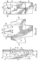
- the carrier is formed from the blank 50, wherein portions corresponding to similar elements of the carrier are identified by the same reference numerals.
- the blank is a single sheet of material, preferably paperboard, comprising a centrally located bottom panel section 46 connected to the side panel sections 12 along fold lines 52.
- the inner top panel flap 16 is connected to one of the side panel sections 12 along fold line 54, while the outer top panel flap 18 is connected to the other side panel section 12 along fold line 56.
- the lower end panel flaps 24 are connected to the bottom panel section 46 along fold lines 58, and the upper end panel flaps 22 are connected to the inner and outer top panel flaps 16 and 18 along fold lines 60 and 62, respectively.
- the side end panel flaps or dust flaps 26 Connected to the side panel sections 12 along fold lines 64 are the side end panel flaps or dust flaps 26, which contain arcuate score lines 61 terminating at the fold lines 64.
- the fold lines 58, 60, 62 and 64 are all aligned. Also aligned are the upper edges 63 of the dust flaps 26 with the fold line 54, and the lower edges 65 of the dust flaps with the fold line 52.
- Each upper end panel flap 22 includes half sections 66 of the tear-away sections 38, the edges of which are adapted to overlap in a carrier formed from the blank.
- the inner top panel flap 16 includes reinforcing flap 68 which is connected to it along aligned fold lines 70 and 72.
- the portions of the fold lines 60 in the half tear-away sections 66 include slits 67
- the portions of the fold lines 60 in the handle reinforcing flap 68 include a double score line 69.
- the outer edge of the reinforcing flap includes a half handle cutout 74, the length of which is equal and parallel to the fold line 70.
- Slits 76 which are located between the fold lines 70 and 72, separate the reinforcing flap from the inner top panel flap 16 and include arcuate portions 78 of similar shape to the arcuate portions of the handle cutout 74.
- Fabrication of the carrier is carried out in conventional manner after first folding the reinforcing flap 68 under the inner top panel flap 16 so that the half handle cutout 74 is aligned with the outer half of the handle opening 30 and the score lines 69 are directly beneath the slits 67 in the fold line 60.
- the reinforcing flap 68 is glued in the stippled area of FIG. 4 to adhere it to the inner top panel flap 16.
- the blank is then folded along the fold lines 52, 54 and 56 to bring the top panel flaps 16 and 18 together in overlapping relationship, with glue having been applied in the stippled area of FIG. 5 so that the overlapped portions of the top panel flaps are adhered together.
- the upper end panel flaps 22 extending from the inner top panel flap 16 are thus adhered to the upper end panel flaps 22 extending from the outer top panel flap 18 to form the upper end panel flaps extending from the top panel.
- the dust flaps and the upper and lower end panel flaps of the resulting carrier sleeve are conventionally folded out of the loading path of the cans to be packaged to form the interim carrier sleeve configuration illustrated in FIG. 6.
- the end panels of the finished carrier of FIG. 1 are formed in the usual manner by first folding in the dust flaps 26, then folding and gluing the upper and lower end panel flaps 22 and 24 against the dust flaps.
- the handle strap between the handle openings 30 and 32 is comprised of three plies of material comprised of the reinforcement flap 68, the inner top panel flap 16 and the outer top panel flap 16. This adequately reinforces the handle area to protect it against tearing under the stresses of lifting and carrying.
- the thickness of the carrier material has been exaggerated. It will be understood, therefore, that in actual practice the thickness of the strap portion of the handle between the openings 30 and 32 will not be as great with respect to the height of the cans as shown, and the top panel flaps 16 and 18 will be in contact with more, if not all, of the top surface of adjacent cans.
- the design of the invention anticipates upward movement of the top panel as the fingers pull up on the handle while first gripping the strap portion and during lifting and carrying.
- the top panel is adapted to smoothly bow upwardly without tearing at critical areas which normally receive most of the lifting stresses. This is accomplished by the stress relief score lines 34 and 36 which extend from the ends of the handle cutouts to the side panels. Preferably, as illustrated, these lines extend to the corners of the package, thereby transmitting the lifting stresses to the corner folds.
- the reinforcement flap 68 not only provides reinforcement in the handle area, but in the end panels as well.
- the reinforcement flap 68 includes end flaps 69 extending beyond the double score lines 69, which as shown in FIG. 6, provides a triple layer of paperboard in the upper central portion of the end panels. While the slits 67 in the fold line 60 facilitate folding of the overlapped portions of the upper end panel flaps when they are pivoted up to make room for the cans to be loaded through the open ends of the carrier sleeve, they would normally tend to cause the fold line 60 to tear in this area.
- the double score line 69 underlies the slits 67 of the fold lines 60, reinforcing and preventing tearing in this area.
- FIG. 8 which illustrates the end of the carrier with the dust flaps in their final closed position, but before the upper and lower end flaps have been folded into place, it can be seen that the upper edges 63 of the dust flaps 26 are substantially parallel to and in contact with the top panel 14, while their lower edges 65 are substantially parallel to and in contact with the bottom panel 46. This is a result of the upper and lower edges 63 and 65 being aligned with the fold lines 54 and 52, respectively, as shown in FIG. 4.
- the dust flaps thus have a height substantially equal to the height of the end panels, extending directly from the top panel to the bottom panel, thereby being able to transmit compressive stresses caused by stacking and handling operations directly from the top panel to the bottom panel.
- the bottom edge of the dust flaps may contain cutouts, as illustrated, if necessary to provide clearance for rails or other elements of the packaging machine, as long as a substantial length of the edge is in contact with the bottom panel.
- the arcuate score lines 61 in the dust flaps further strengthen the dust flaps so as to resist bowing when the side panels are bowed outward-
- the score lines may take any desired form, such as a series of spaced straight parallel lines, as long as they function to encourage folding along the fold lines 64 and to resist warping or bowing of the dust flaps during folding.
- the invention provides a carrier which can be carried by a handle in the top panel and yet is capable of holding large numbers of cans or other articles. This is made possible by incorporating two layers of stacked articles in the carrier.
- the invention overcomes the tendency of the taller panels of the carrier to bow or become skewed out of square by employing side end panel flaps or dust flaps which extend substantially completely the entire distance from the top panel to the bottom panel. Bowing of the end panels is further resisted by score lines in the dust flaps.
- the end panels are further reinforced by the end portions of the handle reinforcement flap, which fold down into the end panels.
- the score lines connecting the end portions of the handle reinforcement flap to the main reinforcement flap body are aligned with the fold line slits of the upper end flaps to prevent breakout or tearing of these fold lines when the flaps are folded up prior to loading.
- the configuration of the end panel flaps makes it possible to incorporate customer coupons in the carrier in a manner that permits the coupons to be visible and readily removed.
- a coupon 82 shown in broken lines, may be adhered to the inner face of the lower end flap 24 so that when the lower end flap is folded up and adhered to the dust flaps 26, the coupon will extend above the shoulder 84 of the flaps between the upper side edges 86.
- the coupon is thus framed in the opening created by these edges prior to being covered by the upper end panel flaps 22.
- the tear-away sections 66 are removed, the coupon is exposed.
- This overcomes the problem of where and how to locate a coupon so that it will be readily seen by a customer and not be inadvertently destroyed when the carrier is opened. It will be appreciated that the opening cannot be so large as to shorten the upper edges of the side end panels to the point where there is insufficient contact between the upper edge of the side end panel and the top panel of the carrier to enable compressive loads to be transmitted to the bottom panel.
Landscapes
- Engineering & Computer Science (AREA)
- Mechanical Engineering (AREA)
- Cartons (AREA)
- Packages (AREA)
- Stackable Containers (AREA)
- Catalysts (AREA)
- Stacking Of Articles And Auxiliary Devices (AREA)
- Laminated Bodies (AREA)
- Transition And Organic Metals Composition Catalysts For Addition Polymerization (AREA)
- Irons (AREA)
- Crystals, And After-Treatments Of Crystals (AREA)
Claims (17)
- Support (10) d'objets contenant plusieurs couches d'objets empilés, comprenant :deux panneaux latéraux (12) comprenant des bords supérieurs (54, 56) et inférieurs (52) ;un panneau inférieur (46) relié aux bords inférieurs (52) des panneaux latéraux (12) ;un panneau supérieur (14) relié aux bords supérieurs (54, 56) des panneaux latéraux (12) ;des panneaux d'extrémité (20) consistant en des rabats collés (22, 24, 26) reliés aux panneaux supérieurs, inférieurs et latéraux, les rabats (26) reliés aux panneaux latéraux (12) le long de lignes de pliage (64) comportant des bords supérieurs (63) et inférieurs (65) qui sont sensiblement en contact avec les et parallèles aux surfaces intérieures des panneaux supérieur (14) et inférieur (46), de sorte que les rabats latéraux de panneau d'extrémité (26) se prolongent sensiblement sur la totalité de la distance allant du panneau supérieur au panneau inférieur ;les plusieurs couches d'objets C1, C2 ayant des extrémités supérieure et inférieure, les objets de chaque couche étant disposés en relation d'empilement bout à bout avec les objets de la couche voisine suivante, l'extrémité inférieure des objets, de la couche inférieure étant adjacente au panneau inférieur du support et l'extrémité supérieure des objets de la couche supérieure étant adjacente au panneau supérieur du support lorsque le support repose sur le panneau inférieur ;les rabats latéraux (26) de panneau d'extrémité comportant plusieurs lignes d'entaille espacées (61) pour résister au bombage desdits rabats (26) lorsque lesdits rabats (26) sont pliés autour de leurs lignes de pliage (64).
- Support d'objets selon la revendication 1, dans lequel le panneau supérieur (14) se compose d'un rabat intérieur (16) relié au bord supérieur de l'un des panneaux latéraux (12) le long d'une ligne de pliage (54) et d'un rabat extérieur en chevauchement (18) relié au bord supérieur de l'autre panneau latéral (12) le long d'une ligne de pliage (56) et dans lequel le panneau supérieur comprend un moyen renforcé (48) de poignée.
- Support d'objets selon la revendication 2, dans lequel les rabats intérieur (16) et extérieur (18) de panneau supérieur comprennent des trous espacés de poignée (30, 32) ménageant une sangle de poignée entre eux, le rabat intp'rieur (16) du panneau supérieur ayant un rabat de renfort (68) qui lui est relié par pliage et qui est en contact de face à face avec le côté inférieur du rabat intérieur de panneau supérieur, le rabat de renfort ayant une découpe (74) alignée sur le trou de poignée (30) du rabat intérieur de panneau supérieur.
- Support d'objets selon la revendication 3, dans lequel les rabats de panneau d'extrémité reliés au panneau supérieur (14) consistent en des rabats supérieurs (22) de panneau d'extrémité reliés à chacun du rabat intérieur (16) et du rabat extérieur (18) de panneau supérieur par des lignes de pliage (60, 62), les rabats supérieurs de panneau d'extrémité qui sont reliés au rabat extérieur de panneau extérieur chevauchant les rabats supérieurs de panneau d'extrémité reliés au rabat intérieur de panneau supérieur et le rabat de renfort (68) se prolongeant dans la zone des rabats de panneau d'extrémité.
- Support d'objets selon la revendication 4, dans lequel les lignes de pliage (60) des rabats supérieurs d'extrémité comportent des fentes (67) dans les zones de chevauchement des rabats supérieurs (22) de panneau d'extrémité.
- Support d'objets selon la revendication 5, dans lequel le rabat de renfort (68) comporte des lignes d'entaille (69) alignées sur les parties fendues (67) des lignes de pliage des rabats supérieurs d'extrémité.
- Support d'objets selon la revendication 1, dans lequel au moins certaines des lignes espacées d'entaille aboutissent aux lignes de pliage (64) reliant les rabats latéraux (26) de panneau d'extrémité aux panneaux latéraux (12).
- Support d'objets selon la revendication 7, dans lequel les lignes espacées d'entaille consistent en lignes courbes de pliage (61) dont les extrémités aboutissent aux lignes de pliage (64) reliant les rabats latéraux (26) de panneau d'extrémité aux panneaux latéraux (12).
- Support d'objets selon la revendication 1, dans lequel le panneau supérieur se compose d'un rabat intérieur (16) relié au bord supérieur de l'un des panneaux latéraux le long d'une ligne de pliage (54) et d'un rabat extérieur en chevauchement (18) relié au bord supérieur de l'autre panneau latéral le long d'une ligne de pliage (56), les rabats intérieur et extérieur comprenant des parties à chevauchement de déchirure (66) pour donner accès à l'intérieur du support.
- Support d'objets selon la revendication 9, dans lequel les rabats supérieurs (22) et inférieurs (24) de panneau d'extrémité se chevauchent et sont collés aux rabats latéraux (26) de panneau d'extrémité, les rabats latéraux de panneau d'extrémité comportant des bords espacés (86) dans les parties auxquelles sont superposés les rabats supérieurs (22) de panneau d'extrémité, de manière qu'un coupon (82) fixé à un rabat inférieur de panneau d'extrémité soit visible et accessible lorsque la partie en chevauchement de déchirure est enlevée.
- Flan (50) destiné à la formation d'un support d'objets conçu pour contenir plusieurs couches d'objets empilés, comprenant :un segment (46) de panneau inférieur relié sur les bords opposés, le long de lignes de pliage (52), à des segments (12) de panneau latéral ;un rabat extérieur (18) de panneau supérieur relié à l'un des segments de panneau latéral (12) le long d'une ligne de pliage (56) et un rabat intérieur (16) de panneau supérieur relié à l'autre segment de panneau latéral (12) le long d'une ligne de pliage (54) ;des rabats inférieurs (24) de panneau d'extrémité reliés au segment (46) de panneau inférieur le long de lignes de pliage (58) ;des rabats supérieurs (22) de panneau d'extrémité reliés aux rabats (16, 18) de panneau supérieur le long de lignes de pliage (60, 62) ;des rabats latéraux (26) de panneau d'extrémité reliés aux segments (12) de panneau latéral le long de lignes de pliage (64) qui s'étendent perpendiculairement du segment de panneau inférieur (46) à un rabat de panneau supérieur (16, 18), les rabats de panneau d'extrémité situés sur chaque côté du flan étant destinés à être collés l'un à l'autre de manière à former des panneaux d'extrémité du support ;les rabats latéraux (26) de panneau d'extrémité comportant des bords supérieurs (63) et inférieurs (65) qui sont orientés de manière à s'éloigner des segments (12) de panneau latéral et qui correspondent à des parties importantes de bords supérieurs et inférieurs des rabats latéraux de panneau d'extrémité situés dans un support formé du flan, lesdits bords supérieurs (63) étant sensiblement alignés sur les lignes de pliage (54) reliant les segments (12) de panneau latéral aux rabats (16, 18) de panneau supérieur et lesdits bords inférieurs (65) étant sensiblement alignés sur les ligne de pliage (52) reliant les segments de panneau latéral (12) au segment de panneau inférieur (46) ;les rabats latéraux (26) de panneau d'extrémité comportant plusieurs lignes espacées d'entaille (61) pour leur permettre de résister au bombage desdits rabats latéraux (26) de panneau d'extrémité lorsque lesdits rabats sont pliés autour de leurs lignes de pliage (64).
- Flan de support selon la revendication 11, dans lequel les rabats intérieur (16) et extérieur de panneau supérieur sont destinés à se chevaucher dans un support formé du flan, chaque rabat de panneau supérieur comprenant un trou de poignée (30, 32), ceux-ci étant réalisés de manière à être distants l'un de l'autre dans le support, de façon à ménager une sangle de poignée entre eux, le rabat intérieur, (16) de panneau supérieur ayant un rabat de renfort (68) qui lui est relié par pliage et qui est destiné à être en contact de face à face avec le côté inférieur du rabat intérieur de panneau supérieur dans un support formé du flan.
- Flan de support selon la revendication 12, dans lequel le rabat de renfort (68) se prolonge au-delà des lignes de pliage (60) reliant les rabats de panneau supérieur (16, 18) aux rabats supérieurs (22) de panneau d'extrémité de manière à renforcer les rabats supérieurs (22) de panneau d'extrémité dans un support formé du flan.
- Flan de support selon la revendication 13, dans lequel les rabats supérieurs (22) de panneau d'extrémité sont destinés à se chevaucher dans un support formé du flan, les lignes de pliage (60, 62) reliant les rabats supérieurs (22) de panneau d'extrémité aux rabats intérieur (16) et extérieur (18) de panneau supérieur comportant des fentes (67) dans les zones de chevauchement des rabats supérieurs de panneau d'extrémité.
- Flan de support selon la revendication 14, dans lequel le rabat de renfort (68) comporte des lignes d'entaille (69) alignées sur les parties fendues (67) des lignes de pliage des rabats supérieurs d'extrémité.
- Flan de support selon la revendication 11, dans lequel au moins certaines des lignes espacées d'entaille aboutissent aux lignes de pliage (64) reliant les rabats latéraux (26) de panneau d'extrémité aux segments de panneau latéral (12).
- Flan de support selon la revendication 16, dans lequel les lignes espacées d'entaille consistent en des lignes courbes de pliage (61) dont les extrémités aboutissent aux lignes de pliage (64) reliant les rabats latéraux (26) de panneau d'extrémité aux segments (12) de panneau latéral.
Applications Claiming Priority (3)
| Application Number | Priority Date | Filing Date | Title |
|---|---|---|---|
| US87567 | 1993-07-01 | ||
| US08/087,567 US5297725A (en) | 1993-07-01 | 1993-07-01 | Carrier for stacked articles |
| PCT/US1994/007244 WO1995001284A1 (fr) | 1993-07-01 | 1994-06-24 | Support pour des articles empiles |
Publications (3)
| Publication Number | Publication Date |
|---|---|
| EP0659143A1 EP0659143A1 (fr) | 1995-06-28 |
| EP0659143A4 EP0659143A4 (fr) | 1997-05-28 |
| EP0659143B1 true EP0659143B1 (fr) | 1999-08-18 |
Family
ID=22205943
Family Applications (1)
| Application Number | Title | Priority Date | Filing Date |
|---|---|---|---|
| EP94922032A Expired - Lifetime EP0659143B1 (fr) | 1993-07-01 | 1994-06-24 | Support pour des articles empiles |
Country Status (15)
| Country | Link |
|---|---|
| US (1) | US5297725A (fr) |
| EP (1) | EP0659143B1 (fr) |
| JP (1) | JPH08500805A (fr) |
| KR (1) | KR950702924A (fr) |
| AT (1) | ATE183462T1 (fr) |
| AU (1) | AU680925B2 (fr) |
| BR (1) | BR9405436A (fr) |
| CA (1) | CA2141671C (fr) |
| CO (1) | CO4230126A1 (fr) |
| DE (1) | DE69420118T2 (fr) |
| ES (1) | ES2134354T3 (fr) |
| FI (1) | FI950675A0 (fr) |
| NZ (1) | NZ269060A (fr) |
| WO (1) | WO1995001284A1 (fr) |
| ZA (1) | ZA944774B (fr) |
Cited By (6)
| Publication number | Priority date | Publication date | Assignee | Title |
|---|---|---|---|---|
| US7100798B2 (en) | 2001-01-09 | 2006-09-05 | Graphic Packaging International, Inc. | Carton with an improved dispensing feature |
| US7401711B2 (en) | 2004-02-10 | 2008-07-22 | Graphic Packaging International, Inc. | Carton having improved opening features |
| US7621438B2 (en) | 2004-02-10 | 2009-11-24 | Graphic Packaging International, Inc. | Carton having opening and positioning features |
| US8167194B2 (en) | 2005-07-22 | 2012-05-01 | Graphic Packaging International, Inc. | Carton with opening feature and blank |
| US8220702B2 (en) | 2004-10-29 | 2012-07-17 | Graphic Packaging International, Inc. | Carton having novel opening features |
| US8408392B2 (en) | 2003-02-12 | 2013-04-02 | Graphic Packaging International, Inc. | Dispensing system for double stack carton |
Families Citing this family (82)
| Publication number | Priority date | Publication date | Assignee | Title |
|---|---|---|---|---|
| US5320277A (en) * | 1993-07-09 | 1994-06-14 | The Mead Corporation | Article carrier reinforcing structure |
| US5379944A (en) * | 1994-05-26 | 1995-01-10 | The Mead Corporation | Heavy duty article carrier |
| GB9413862D0 (en) * | 1994-07-08 | 1994-08-24 | Mead Corp | Beverage carton with strap type carrying handle |
| US5505372A (en) * | 1994-10-28 | 1996-04-09 | Graphic Packaging Corporation | Carton blank and carton |
| US5647483A (en) * | 1996-02-23 | 1997-07-15 | Riverwood International Corporation | Article carrier with reinforced handle |
| US6425520B1 (en) | 2000-10-24 | 2002-07-30 | International Paper Company | Beverage carrier |
| DE20112228U1 (de) * | 2001-07-06 | 2002-11-14 | A & R Carton Gmbh | Flaschenträger |
| US6971572B2 (en) * | 2001-10-24 | 2005-12-06 | Meadwestvaco Packaging Systems, Llc | Carton |
| US20040099558A1 (en) * | 2002-06-21 | 2004-05-27 | Oliff James R. | Dispensing feature with built-in combination retention and ad panel |
| US20040089671A1 (en) | 2002-11-07 | 2004-05-13 | The C.W. Zumbiel Company | Carton with dispenser |
| NL1023074C2 (nl) * | 2003-04-01 | 2004-10-04 | Heineken Tech Services | Multipack en plano en werkwijze voor de vervaardiging daarvan. |
| US7614497B2 (en) | 2003-10-15 | 2009-11-10 | Graphic Packaging International, Inc. | Display/vending carton |
| ES2320933T3 (es) * | 2005-12-23 | 2009-05-29 | Graphic Packaging International, Inc. | Caja de carton con asa de sujecion. |
| CN101432203B (zh) * | 2006-03-01 | 2012-01-04 | 印刷包装国际公司 | 带有多层把手的纸箱 |
| US20070251982A1 (en) * | 2006-05-01 | 2007-11-01 | Brand Kirsten L | Gusseted Carton |
| WO2009117562A1 (fr) * | 2008-03-19 | 2009-09-24 | Graphic Packaging International, Inc. | Carton à poignée |
| BRPI0911313B1 (pt) | 2008-04-14 | 2019-04-30 | Graphic Packaging International, Llc | Caixa, matriz para formar uma caixa, e método de formar uma caixa para conter uma pluralidade de recipientes |
| CA2738241C (fr) * | 2008-10-30 | 2014-05-06 | Graphic Packaging International, Inc. | Glaciere possedant une poignee |
| WO2010083275A2 (fr) * | 2009-01-16 | 2010-07-22 | Graphic Packaging International, Inc. | Caisse en carton ayant un insert de renforcement |
| MX2011008740A (es) * | 2009-02-24 | 2011-09-06 | Graphic Packaging Int Inc | Caja de carton con mango. |
| EP2408686B1 (fr) * | 2009-03-17 | 2014-06-25 | Graphic Packaging International, Inc. | Carton avec panneau supérieur renforcé |
| WO2011008854A2 (fr) * | 2009-07-14 | 2011-01-20 | Graphic Packaging International, Inc. | Carton comprenant une garniture |
| CA2771185C (fr) * | 2009-08-17 | 2014-06-03 | Graphic Packaging International, Inc. | Carton avec poignee |
| CA2771898C (fr) | 2009-08-28 | 2014-10-14 | Graphic Packaging International, Inc. | Carton a insert |
| EP2316746B1 (fr) * | 2009-10-30 | 2011-12-07 | Graphic Packaging International, Inc. | Carton |
| US9205948B1 (en) | 2010-03-26 | 2015-12-08 | The C.W. Zumbiel Company | Carton and stress relieving score pattern for handle |
| US9403615B2 (en) * | 2010-03-26 | 2016-08-02 | The C.W. Zumbiel Company | Carton and handle in multi-ply carton material |
| NZ602729A (en) | 2010-05-25 | 2013-08-30 | Graphic Packaging Int Inc | Carton with insert |
| CA2811219A1 (fr) | 2010-09-17 | 2012-03-22 | Graphic Packaging International, Inc. | Boite pliante comportant une poignee |
| EP2616356B1 (fr) | 2010-09-17 | 2016-03-16 | Graphic Packaging International, Inc. | Carton avec insert |
| CA2813422C (fr) * | 2010-10-15 | 2015-02-03 | Graphic Packaging International, Inc. | Carton ayant un panneau superieur renforce |
| EP2630057A4 (fr) | 2010-10-18 | 2014-05-07 | Graphic Packaging Int Inc | Carton ayant une poignée |
| US9376230B2 (en) | 2011-02-23 | 2016-06-28 | Graphic Packaging International, Inc. | Carton with handle and dispenser |
| US8978963B2 (en) | 2011-02-23 | 2015-03-17 | Graphic Packaging International, Inc. | Carton with handle and dispenser |
| EP2814756B1 (fr) | 2012-02-16 | 2017-04-26 | Graphic Packaging International, Inc. | Boîte en carton ayant une poignée renforcée |
| MX343675B (es) | 2012-02-16 | 2016-11-16 | Graphic Packaging Int Inc | Caja de cartón con asa. |
| WO2013130528A1 (fr) | 2012-02-27 | 2013-09-06 | Graphic Packaging International, Inc. | Carton à poignée renforcée |
| NZ631247A (en) | 2012-04-27 | 2016-06-24 | Graphic Packaging Int Inc | Carton with insert |
| US9126716B2 (en) * | 2012-05-11 | 2015-09-08 | Graphic Packaging International, Inc. | Carton with handle |
| ES2620435T3 (es) | 2012-07-17 | 2017-06-28 | Graphic Packaging International, Inc. | Cajas de cartón con inserto |
| AU2013290750B2 (en) | 2012-07-17 | 2017-02-09 | Graphic Packaging International, Llc | Carton with article protection feature |
| US9010620B2 (en) | 2012-08-10 | 2015-04-21 | Graphic Packaging International, Inc. | Carton with handle |
| ES2656077T3 (es) | 2012-08-10 | 2018-02-23 | Graphic Packaging International, Inc. | Caja de cartón con distribuidor |
| BR112015009520B1 (pt) | 2012-11-30 | 2021-09-14 | Graphic Packaging International, Llc | Embalagem para acondicionar uma pluralidade de artigos, blanqueta para formar uma embalagem para acondicionar pelo menos um artigo, e método de formação de uma embalagem para conter pelo menos um artigo |
| WO2014124355A2 (fr) * | 2013-02-11 | 2014-08-14 | Graphic Packaging International, Inc. | Carton doté d'une poignée |
| WO2014130788A1 (fr) | 2013-02-22 | 2014-08-28 | Graphic Packaging International, Inc. | Carton à poignée |
| WO2014186267A1 (fr) | 2013-05-13 | 2014-11-20 | Graphic Packaging International, Inc. | Carton pourvu d'un insert |
| NZ713712A (en) | 2013-05-13 | 2018-02-23 | Graphic Packaging Int Llc | Carton with article protection features |
| US10384846B2 (en) | 2013-05-24 | 2019-08-20 | Graphic Packaging International, Llc | Arrangement of containers in a carton |
| NZ713710A (en) | 2013-05-24 | 2018-05-25 | Graphic Packaging Int Llc | Carton for articles |
| US9598202B2 (en) | 2013-07-24 | 2017-03-21 | Graphic Packaging International, Inc. | Carton with handle |
| NZ719459A (en) | 2013-12-10 | 2018-02-23 | Graphic Packaging Int Llc | Carton with article protection features |
| US9511894B2 (en) | 2014-01-16 | 2016-12-06 | Graphic Packaging International, Inc. | Carton with opening feature |
| EP3110704B1 (fr) | 2014-02-28 | 2018-09-12 | Graphic Packaging International, LLC | Carton comprenant des éléments de protection d'articles |
| US10322845B2 (en) | 2014-03-11 | 2019-06-18 | Graphic Packaging International, Llc | Carton with insert |
| ES2734410T3 (es) | 2014-03-11 | 2019-12-05 | Graphic Packaging Int Llc | Caja de cartón con un elemento de inserción |
| US9636882B2 (en) | 2014-08-19 | 2017-05-02 | Graphic Packaging International, Inc. | Carton with reinforced handle |
| CA2962625C (fr) | 2014-10-27 | 2019-12-03 | Graphic Packaging International, Llc | Carton pour articles |
| CN107148388B (zh) | 2014-10-30 | 2019-08-16 | 印刷包装国际有限责任公司 | 具有手柄的纸箱 |
| CA2961652C (fr) | 2014-10-31 | 2019-08-13 | Graphic Packaging International, Inc. | Carton texturise |
| CA2981076C (fr) | 2015-05-07 | 2019-04-30 | Graphic Packaging International, Inc. | Carton dote d'une poignee |
| US10202228B2 (en) | 2015-10-09 | 2019-02-12 | Graphic Packaging International, Llc | Carton with asymmetrical corners |
| EP3370782A4 (fr) | 2015-11-02 | 2019-07-24 | Pura Scents, Inc. | Distribution de parfum |
| USD809116S1 (en) | 2015-11-02 | 2018-01-30 | Pura Scents | Dispenser |
| USD816506S1 (en) | 2015-11-02 | 2018-05-01 | Pura Scents, Inc. | Vial for a scent dispenser |
| MX2018005225A (es) | 2015-11-18 | 2018-08-15 | Graphic Packaging Int Llc | Caja de carton con asa. |
| WO2017100385A1 (fr) | 2015-12-08 | 2017-06-15 | Graphic Packaging International, Inc. | Carton à poignée |
| EP3414177A4 (fr) | 2016-02-12 | 2019-10-23 | Graphic Packaging International, LLC | Carton à poignée |
| AU2017218125B2 (en) | 2016-02-12 | 2019-10-10 | Graphic Packaging International, Llc | Carton with handle |
| MX2019013765A (es) * | 2017-05-19 | 2020-01-30 | Westrock Packaging Systems Llc | Caja de carton y plantilla para caja de carton. |
| US11305924B2 (en) | 2018-01-23 | 2022-04-19 | Graphie Packaging International, LLC | Carrier with handle features |
| USD854412S1 (en) | 2018-02-22 | 2019-07-23 | Graphic Packaging International, Llc | Carrier |
| USD867900S1 (en) | 2018-03-01 | 2019-11-26 | Graphic Packaging International, Llc | Carrier |
| US11142383B2 (en) | 2018-10-09 | 2021-10-12 | Graphic Packaging International, Llc | Carton with handle |
| USD881690S1 (en) | 2018-12-31 | 2020-04-21 | Graphic Packaging International, Llc | Carton |
| USD885887S1 (en) | 2019-01-03 | 2020-06-02 | Graphic Packaging International, Llc | Carton |
| USD898565S1 (en) | 2019-04-23 | 2020-10-13 | Graphic Packaging International, Llc | Carton |
| US11254465B2 (en) | 2019-07-18 | 2022-02-22 | Graphic Packaging International, Llc | Carton with attachment features |
| US11912484B2 (en) | 2020-05-22 | 2024-02-27 | Graphic Packaging International, Llc | Carton for containers |
| USD966098S1 (en) | 2020-07-14 | 2022-10-11 | Graphic Packaging International, Llc | Carton |
| AU2024234782A1 (en) * | 2023-03-10 | 2025-09-04 | Graphic Packaging International, Llc | Carton for containers |
| USD1102887S1 (en) | 2023-10-31 | 2025-11-25 | Graphic Packaging International, Llc | Carton for containers |
Family Cites Families (15)
| Publication number | Priority date | Publication date | Assignee | Title |
|---|---|---|---|---|
| US2681143A (en) * | 1950-02-17 | 1954-06-15 | Waldorf Paper Prod Co | Dome top carrier carton |
| US2797856A (en) * | 1953-01-02 | 1957-07-02 | Waldorf Paper Prod Co | Handled cartons |
| US2911136A (en) * | 1958-02-20 | 1959-11-03 | Continental Can Co | Reinforced handle construction for paperboard cartons |
| US3076591A (en) * | 1961-02-09 | 1963-02-05 | Patent & Licensing Corp | Carton with carrier handle |
| US3994432A (en) * | 1974-10-07 | 1976-11-30 | Reynolds Metals Company | Carton and blank for making same |
| US3904036A (en) * | 1974-11-15 | 1975-09-09 | Mead Corp | Fully enclosed bottle container |
| US4304332A (en) * | 1979-10-26 | 1981-12-08 | Danti Bernard R | Package |
| US4331289A (en) * | 1981-05-13 | 1982-05-25 | Manville Service Corporation | Four-ply handled carton |
| US4396143A (en) * | 1981-08-31 | 1983-08-02 | Manville Service Corporation | Multiple article beverage package |
| US4679725A (en) * | 1984-02-06 | 1987-07-14 | Manville Sales Corporation | End closure lock |
| US4577799A (en) * | 1985-01-28 | 1986-03-25 | The Mead Corporation | Panel interlocking means |
| GB8715656D0 (en) * | 1987-07-03 | 1987-08-12 | St Regis Packaging Ltd | Carton |
| WO1993015971A1 (fr) * | 1992-02-11 | 1993-08-19 | Riverwood International Corporation | Dispositif de transport d'articles empiles |
| US5246113A (en) * | 1992-02-11 | 1993-09-21 | Riverwood International Corporation | Carrier for stacked articles |
| US5320277A (en) * | 1993-07-09 | 1994-06-14 | The Mead Corporation | Article carrier reinforcing structure |
-
1993
- 1993-07-01 US US08/087,567 patent/US5297725A/en not_active Expired - Lifetime
-
1994
- 1994-06-24 WO PCT/US1994/007244 patent/WO1995001284A1/fr not_active Ceased
- 1994-06-24 EP EP94922032A patent/EP0659143B1/fr not_active Expired - Lifetime
- 1994-06-24 KR KR1019950700715A patent/KR950702924A/ko not_active Withdrawn
- 1994-06-24 NZ NZ269060A patent/NZ269060A/en unknown
- 1994-06-24 JP JP7503586A patent/JPH08500805A/ja not_active Ceased
- 1994-06-24 AU AU72519/94A patent/AU680925B2/en not_active Ceased
- 1994-06-24 ES ES94922032T patent/ES2134354T3/es not_active Expired - Lifetime
- 1994-06-24 CA CA002141671A patent/CA2141671C/fr not_active Expired - Fee Related
- 1994-06-24 BR BR9405436-3A patent/BR9405436A/pt not_active IP Right Cessation
- 1994-06-24 AT AT94922032T patent/ATE183462T1/de not_active IP Right Cessation
- 1994-06-24 FI FI950675A patent/FI950675A0/fi not_active Application Discontinuation
- 1994-06-24 DE DE69420118T patent/DE69420118T2/de not_active Expired - Fee Related
- 1994-07-01 CO CO94028859A patent/CO4230126A1/es unknown
- 1994-07-01 ZA ZA944774A patent/ZA944774B/xx unknown
Cited By (17)
| Publication number | Priority date | Publication date | Assignee | Title |
|---|---|---|---|---|
| US8579154B2 (en) | 2001-01-09 | 2013-11-12 | Graphic Packaging International, Inc. | Carton with an improved dispensing feature |
| US7175047B2 (en) | 2001-01-09 | 2007-02-13 | Graphic Packaging International, Inc. | Carton with an improved dispensing feature |
| US9392888B2 (en) | 2001-01-09 | 2016-07-19 | Graphic Packaging International, Inc. | Carton with an improved dispensing feature |
| US7523842B2 (en) | 2001-01-09 | 2009-04-28 | Graphic Packaging International, Inc. | Carton with an improved dispensing feature |
| US8887952B2 (en) | 2001-01-09 | 2014-11-18 | Graphic Packaging International, Inc. | Carton with an improved dispensing feature |
| US8123072B2 (en) | 2001-01-09 | 2012-02-28 | Graphic Packaging International, Inc. | Carton with an improved dispensing feature |
| US7100798B2 (en) | 2001-01-09 | 2006-09-05 | Graphic Packaging International, Inc. | Carton with an improved dispensing feature |
| US8302811B2 (en) | 2001-01-09 | 2012-11-06 | Graphic Packaging International, Inc. | Carton with an improved dispensing feature |
| US8408392B2 (en) | 2003-02-12 | 2013-04-02 | Graphic Packaging International, Inc. | Dispensing system for double stack carton |
| US8881901B2 (en) | 2003-02-12 | 2014-11-11 | Graphic Packaging International, Inc. | Dispensing system for double stack carton |
| US9452874B2 (en) | 2003-02-12 | 2016-09-27 | Graphic Packaging International, Inc. | Dispensing system for double stack carton |
| US7621438B2 (en) | 2004-02-10 | 2009-11-24 | Graphic Packaging International, Inc. | Carton having opening and positioning features |
| US7401711B2 (en) | 2004-02-10 | 2008-07-22 | Graphic Packaging International, Inc. | Carton having improved opening features |
| US8444046B2 (en) | 2004-10-29 | 2013-05-21 | Graphic Packaging International, Inc. | Carton having novel opening features |
| US8220702B2 (en) | 2004-10-29 | 2012-07-17 | Graphic Packaging International, Inc. | Carton having novel opening features |
| US8550332B2 (en) | 2005-07-22 | 2013-10-08 | Graphic Packaging International, Inc. | Carton with opening feature and blank |
| US8167194B2 (en) | 2005-07-22 | 2012-05-01 | Graphic Packaging International, Inc. | Carton with opening feature and blank |
Also Published As
| Publication number | Publication date |
|---|---|
| FI950675L (fi) | 1995-02-15 |
| ES2134354T3 (es) | 1999-10-01 |
| AU680925B2 (en) | 1997-08-14 |
| FI950675A7 (fi) | 1995-02-15 |
| KR950702924A (ko) | 1995-08-23 |
| EP0659143A4 (fr) | 1997-05-28 |
| ZA944774B (en) | 1995-02-22 |
| DE69420118D1 (de) | 1999-09-23 |
| WO1995001284A1 (fr) | 1995-01-12 |
| ATE183462T1 (de) | 1999-09-15 |
| CA2141671C (fr) | 2005-05-03 |
| DE69420118T2 (de) | 2000-04-20 |
| US5297725A (en) | 1994-03-29 |
| FI950675A0 (fi) | 1995-02-15 |
| NZ269060A (en) | 1997-10-24 |
| JPH08500805A (ja) | 1996-01-30 |
| CO4230126A1 (es) | 1995-10-19 |
| AU7251994A (en) | 1995-01-24 |
| BR9405436A (pt) | 1999-09-08 |
| CA2141671A1 (fr) | 1995-01-12 |
| EP0659143A1 (fr) | 1995-06-28 |
Similar Documents
| Publication | Publication Date | Title |
|---|---|---|
| AU680925B2 (en) | Carrier for stacked articles | |
| US5234102A (en) | Carrier for stacked articles | |
| US5246113A (en) | Carrier for stacked articles | |
| US5072876A (en) | Article carrier with side handles | |
| EP0715590B1 (fr) | Renforcement des poignees d'un carton | |
| US5234103A (en) | Enclosed basket-style carrier | |
| EP0807068A1 (fr) | Support a distributeur d'articles | |
| US5593087A (en) | Open-top container with integral end panels | |
| EP0580844B1 (fr) | Dispositif de transport d'articles empiles | |
| US5575419A (en) | Open-top container with laminated end panels | |
| EP0725749B1 (fr) | Contenant comportant des pattes de maintien des objets | |
| EP1135296A2 (fr) | Dispositif robuste de transport d'articles | |
| HK1075876B (en) | Carton and carton blank |
Legal Events
| Date | Code | Title | Description |
|---|---|---|---|
| PUAI | Public reference made under article 153(3) epc to a published international application that has entered the european phase |
Free format text: ORIGINAL CODE: 0009012 |
|
| AK | Designated contracting states |
Kind code of ref document: A1 Designated state(s): AT BE CH DE DK ES FR GB GR IE IT LI LU MC NL PT SE |
|
| 17P | Request for examination filed |
Effective date: 19950705 |
|
| A4 | Supplementary search report drawn up and despatched |
Effective date: 19970408 |
|
| AK | Designated contracting states |
Kind code of ref document: A4 Designated state(s): AT BE CH DE DK ES FR GB GR IE IT LI LU MC NL PT SE |
|
| 17Q | First examination report despatched |
Effective date: 19980408 |
|
| GRAG | Despatch of communication of intention to grant |
Free format text: ORIGINAL CODE: EPIDOS AGRA |
|
| GRAG | Despatch of communication of intention to grant |
Free format text: ORIGINAL CODE: EPIDOS AGRA |
|
| GRAH | Despatch of communication of intention to grant a patent |
Free format text: ORIGINAL CODE: EPIDOS IGRA |
|
| GRAH | Despatch of communication of intention to grant a patent |
Free format text: ORIGINAL CODE: EPIDOS IGRA |
|
| GRAA | (expected) grant |
Free format text: ORIGINAL CODE: 0009210 |
|
| AK | Designated contracting states |
Kind code of ref document: B1 Designated state(s): AT BE CH DE DK ES FR GB GR IE IT LI LU MC NL PT SE |
|
| PG25 | Lapsed in a contracting state [announced via postgrant information from national office to epo] |
Ref country code: SE Free format text: THE PATENT HAS BEEN ANNULLED BY A DECISION OF A NATIONAL AUTHORITY Effective date: 19990818 Ref country code: LI Free format text: LAPSE BECAUSE OF FAILURE TO SUBMIT A TRANSLATION OF THE DESCRIPTION OR TO PAY THE FEE WITHIN THE PRESCRIBED TIME-LIMIT Effective date: 19990818 Ref country code: GR Free format text: LAPSE BECAUSE OF NON-PAYMENT OF DUE FEES Effective date: 19990818 Ref country code: CH Free format text: LAPSE BECAUSE OF FAILURE TO SUBMIT A TRANSLATION OF THE DESCRIPTION OR TO PAY THE FEE WITHIN THE PRESCRIBED TIME-LIMIT Effective date: 19990818 Ref country code: AT Free format text: LAPSE BECAUSE OF FAILURE TO SUBMIT A TRANSLATION OF THE DESCRIPTION OR TO PAY THE FEE WITHIN THE PRESCRIBED TIME-LIMIT Effective date: 19990818 |
|
| REF | Corresponds to: |
Ref document number: 183462 Country of ref document: AT Date of ref document: 19990915 Kind code of ref document: T |
|
| REG | Reference to a national code |
Ref country code: CH Ref legal event code: EP |
|
| REF | Corresponds to: |
Ref document number: 69420118 Country of ref document: DE Date of ref document: 19990923 |
|
| REG | Reference to a national code |
Ref country code: ES Ref legal event code: FG2A Ref document number: 2134354 Country of ref document: ES Kind code of ref document: T3 |
|
| ET | Fr: translation filed | ||
| REG | Reference to a national code |
Ref country code: IE Ref legal event code: FG4D |
|
| PG25 | Lapsed in a contracting state [announced via postgrant information from national office to epo] |
Ref country code: DK Free format text: LAPSE BECAUSE OF FAILURE TO SUBMIT A TRANSLATION OF THE DESCRIPTION OR TO PAY THE FEE WITHIN THE PRESCRIBED TIME-LIMIT Effective date: 19991118 |
|
| REG | Reference to a national code |
Ref country code: PT Ref legal event code: SC4A Free format text: AVAILABILITY OF NATIONAL TRANSLATION Effective date: 19990819 |
|
| REG | Reference to a national code |
Ref country code: CH Ref legal event code: PL |
|
| PLBE | No opposition filed within time limit |
Free format text: ORIGINAL CODE: 0009261 |
|
| STAA | Information on the status of an ep patent application or granted ep patent |
Free format text: STATUS: NO OPPOSITION FILED WITHIN TIME LIMIT |
|
| PG25 | Lapsed in a contracting state [announced via postgrant information from national office to epo] |
Ref country code: LU Free format text: LAPSE BECAUSE OF NON-PAYMENT OF DUE FEES Effective date: 20000624 |
|
| PG25 | Lapsed in a contracting state [announced via postgrant information from national office to epo] |
Ref country code: MC Free format text: THE PATENT HAS BEEN ANNULLED BY A DECISION OF A NATIONAL AUTHORITY Effective date: 20000630 |
|
| 26N | No opposition filed | ||
| PG25 | Lapsed in a contracting state [announced via postgrant information from national office to epo] |
Ref country code: PT Free format text: LAPSE BECAUSE OF NON-PAYMENT OF DUE FEES Effective date: 20001231 |
|
| REG | Reference to a national code |
Ref country code: PT Ref legal event code: MM4A Free format text: LAPSE DUE TO NON-PAYMENT OF FEES Effective date: 20001231 |
|
| REG | Reference to a national code |
Ref country code: GB Ref legal event code: IF02 |
|
| PGFP | Annual fee paid to national office [announced via postgrant information from national office to epo] |
Ref country code: ES Payment date: 20040708 Year of fee payment: 11 |
|
| PGFP | Annual fee paid to national office [announced via postgrant information from national office to epo] |
Ref country code: NL Payment date: 20050531 Year of fee payment: 12 |
|
| PGFP | Annual fee paid to national office [announced via postgrant information from national office to epo] |
Ref country code: GB Payment date: 20050615 Year of fee payment: 12 |
|
| PGFP | Annual fee paid to national office [announced via postgrant information from national office to epo] |
Ref country code: FR Payment date: 20050617 Year of fee payment: 12 |
|
| PGFP | Annual fee paid to national office [announced via postgrant information from national office to epo] |
Ref country code: IE Payment date: 20050621 Year of fee payment: 12 |
|
| PG25 | Lapsed in a contracting state [announced via postgrant information from national office to epo] |
Ref country code: ES Free format text: LAPSE BECAUSE OF NON-PAYMENT OF DUE FEES Effective date: 20050625 |
|
| PGFP | Annual fee paid to national office [announced via postgrant information from national office to epo] |
Ref country code: BE Payment date: 20050725 Year of fee payment: 12 |
|
| PGFP | Annual fee paid to national office [announced via postgrant information from national office to epo] |
Ref country code: DE Payment date: 20050801 Year of fee payment: 12 |
|
| PG25 | Lapsed in a contracting state [announced via postgrant information from national office to epo] |
Ref country code: GB Free format text: LAPSE BECAUSE OF NON-PAYMENT OF DUE FEES Effective date: 20060624 |
|
| PG25 | Lapsed in a contracting state [announced via postgrant information from national office to epo] |
Ref country code: IE Free format text: LAPSE BECAUSE OF NON-PAYMENT OF DUE FEES Effective date: 20060626 |
|
| PG25 | Lapsed in a contracting state [announced via postgrant information from national office to epo] |
Ref country code: BE Free format text: LAPSE BECAUSE OF NON-PAYMENT OF DUE FEES Effective date: 20060630 |
|
| PGFP | Annual fee paid to national office [announced via postgrant information from national office to epo] |
Ref country code: IT Payment date: 20060630 Year of fee payment: 13 |
|
| REG | Reference to a national code |
Ref country code: ES Ref legal event code: FD2A Effective date: 20050625 |
|
| PG25 | Lapsed in a contracting state [announced via postgrant information from national office to epo] |
Ref country code: NL Free format text: LAPSE BECAUSE OF NON-PAYMENT OF DUE FEES Effective date: 20070101 |
|
| PG25 | Lapsed in a contracting state [announced via postgrant information from national office to epo] |
Ref country code: DE Free format text: LAPSE BECAUSE OF NON-PAYMENT OF DUE FEES Effective date: 20070103 |
|
| GBPC | Gb: european patent ceased through non-payment of renewal fee |
Effective date: 20060624 |
|
| NLV4 | Nl: lapsed or anulled due to non-payment of the annual fee |
Effective date: 20070101 |
|
| REG | Reference to a national code |
Ref country code: IE Ref legal event code: MM4A |
|
| REG | Reference to a national code |
Ref country code: FR Ref legal event code: ST Effective date: 20070228 |
|
| BERE | Be: lapsed |
Owner name: *RIVERWOOD INTERNATIONAL CORP. Effective date: 20060630 |
|
| PG25 | Lapsed in a contracting state [announced via postgrant information from national office to epo] |
Ref country code: FR Free format text: LAPSE BECAUSE OF NON-PAYMENT OF DUE FEES Effective date: 20060630 |
|
| PG25 | Lapsed in a contracting state [announced via postgrant information from national office to epo] |
Ref country code: IT Free format text: LAPSE BECAUSE OF NON-PAYMENT OF DUE FEES Effective date: 20070624 |